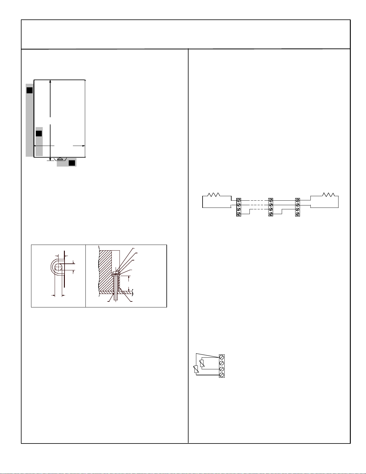
Network Interface Unit
October 2000 GFK-1551D
4
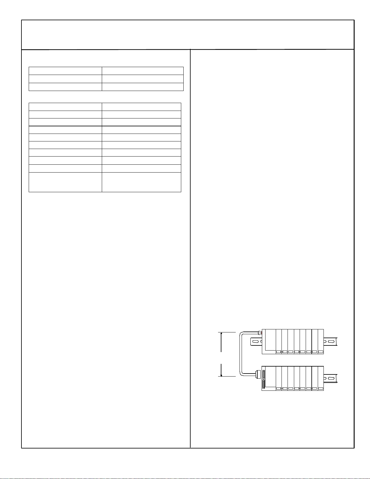
RS-485 Differential Expansion System
A multi-rack expansion system requires an Expansion Transmitter
Module in the NIU I/O Station. Up to seven expansion racks can be
included in the system. With any non-isolated Expansion Receiver
Module in the system, the total overall length of the expansion cable
can be up to 15 meters.
With all Isolated Receiver Modules, the total overall length of the
expansion cable can be up to 750 meters.
The expansion bus must be terminated with terminator plug *ACC201
(included with the Expansion Transmitter).
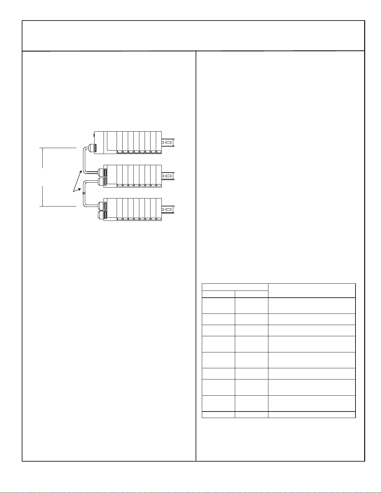
ExpansionRack 1
Terminator
15M with any
750M with all
I/O Station Main Rack (0)
ExpansionRack 7ICBL601,
Communications in an Expansion System
The NIU in the main rack communicates with the expansion racks
through a high-speed serial interface. The frequency used depends on
the types of expansion receivers in the expansion rack(s).
§In a Two-Rack Local system, the communications frequency is
3MHz.
§In Differential system, the NIU communications frequency is 3MHz
unless at least one isolated expansion receiver is installed.
Modules for an Expansion System
Expansion racks are built from the same carrier bases and I/O
modules that are allowed in main rack applications. Note the special
revisions required for some analog modules mentioned above.
Configuration and Installation Notes for Expansion Systems
§The NIU must have its rack dial set to rack 1 or it will not auto-
configure. The Expansion Receiver modules also have Rack ID
selection dials. Each must be set correctly as described in the
Expansion Module datasheets.
§In a multiple-rack expansion system, any available rack number
can be used for a new expansion rack but they must all be
unique (no duplicate rack numbers). It is best to assign
expansion racks numbers from lowest (1) to highest (7) as they
are installed. That is most compatible with the NIU auto-
configuration feature. Auto-configuration automatically assigns
reference addresses to I/O points and channels as it configures
them. Autoconfiguration starts in the main rack and proceeds
through the slots and additional racks in order, assigning
references from lowest to highest.
§To force auto configuration for expansion racks, first power down
the NIU. Remove the transmitter module from the NIU or remove
the expansion cable at the transmitter. Power up the NIU and let
it autoconfigure. Power the NIU down again, reattach the
transmitter or cable and power up the NIU again.
§In an local system, the NIU rack and the expansion rack may be on
different power supplies if desired. If so, on a single-ended or
differential system, disconnecting the cable between the
NIU/transmitter and receivers may cause disruptions on the bus.
§In a multiple-rack expansion system, if a new expansion rack is added
in the future, it should be assigned a rack address that is higher than
the racks that are already installed. If a new expansion rack with a
lower rack number than those previously auto-configured is installed
and the system is auto-configured, the racks numbered higher than
the new rack number have their I/O reference addresses shifted in the
reference tables. Any existing program logic that uses those
references must then be adjusted to use the new references.
§To add a new expansion rack to the system, the system must be
powered down. After adding the module, according to the
instructions in the Expansion Module datasheet, power up the
system. It will then autoconfigure.
Fault Handling for an Expansion System
This version of the NIU can detect extra, lost, and added expansion racks
as a result of a power cycle.
§When a complete rack is lost, only a “Loss of Rack” fault is generated.
Individual “Loss of Module” faults are suppressed.
§When a rack is added only an “Addition of Rack” fault and any I/O
module mismatch or loss conditions are reported. Individual I/O
module additions are suppressed.
§An “Extra rack” fault is generated when an expansion rack is present
but has not been configured. The Scan LED on the Expansion
Receiver Module is green instead of yellow whenever the Expansion
Receiver is properly configured and is working.
§Hot swapping of Expansion Transmitter Modules is not supported. The
NIU detects the loss and addition of the Expansion Transmitter
Module and generates the appropriate faults.
§If the run-time expansion frequency changes, an “Expansion bus
speed change” fault is generated.
The table below summarizes programmer faults in an expansion system:
Programmer Fault Text
VP/C90 LM90 Fault Description
Expansion Bus
Speed Change Reset of, Addition
of, or extra option
module Expansion bus operating frequency has changed from
250kHz to 3MHz or vice versa.
Addition of rack Addition of, or
extra rack Occurs when a receiver is first configured and when it
returns after being lost.
Loss of, or missing
rack Loss of, or missing
rack Occurs when a properly configured receiver is not
physically present at power up or lost at run-time.
System
Configuration
Mismatch
System
Configuration
Mismatch The configuration stored for a receiver does not match
the physical receiver present.
Extra Rack Addition of, or
extra rack Generated when a receiver is present that is not
currently configured. Also indicates improperly-
numbered rack ID.
Loss of, or missing
option module Loss of, or missing
option module Generated when a properly configured transmitter
module in a differential rack system is not present.
Reset of module Reset of, Addition
of, or extra option
module
Generated when a transmitter in a differential rack
system is either configured for the first time or is now
present after being lost.
Extra module
present but not
configured
Reset of, Addition
of, or extra option
module Generated when a system is configured for single-
ended operation and a transmitter module is present.
Extra Transmitter Expansion Transmitter installed in 2-rack local system