VersaMax* PROFIBUS Network Interface Unit
December 2016 GFK-1552L
2
Fixed for Version 2.21
•PROFIBUS NIU incorrectly reported “Loss of IO module
fault” after auto configuration. When the PROFIBUS NIU was
auto-configured and power-cycled, its fault LED came ON and it
reported a “Loss of I/O module” fault although the module was
connected. This occurred with module IC200MDD841 and all
other intelligent modules.
•Uncorrected Loss of module and Loss of Rack faults were not re-
reported after Clearing All NIU Faults. The PROFIBUS NIU did
not re-report standing Loss of Module and Loss of Rack faults
after clearing all faults by setting bit 7of PNIU control byte either
through application logic or through reference memory in
Machine Edition.
•PROFIBUS NIU Produced Repeated System Configuration
Mismatch Faults When Analog Current Input Module had
Incorrect Jumper Setting. If the jumper-selected input range on
an Analog Current Input Module did not match the hardware
configuration, the NIU produced System Configuration Mismatch
faults every 2 to 5 seconds. With NIU firmware version 2.22, the
NIU does not log this fault repeatedly.
•PROFIBUS NIU always held the input values of a mismatched
module in their last state regardless of the module’s
configuration. For PROFIBUS NIU firmware version 2.22, the
mismatched module’s inputs are correctly set to either hold last
state or default, according to the module’s “Default/Hold Last
State” configuration parameter.
•VersaMax PROFIBUS NIU does not report loss of module for a
module that fails after jumper mismatch is detected. If an I/O
module that has a mis-matched jumper configuration fails or is
removed from the PROFIBUS NIU station after the NIU detects
the mismatch, the NIU will not report the loss of module fault to
its Masters. If the attempt is made to clear all PROFIBUS NIU
faults (by setting 7th bit of PNIU control byte) while this condition
exists, the NIU would not report any fault for this module. In
PROFIBUS NIU firmware version 2.22, the NIU reports the loss
of module fault and lights its Fault LED.
Preinstallation Check
Carefully inspect all shipping containers for damage. If any equipment
is damaged, notify the delivery service immediately. Save the
damaged shipping container for inspection by the delivery service.
After unpacking the equipment, record all serial numbers. Save the
shipping containers and packing material in case it is necessary to
transport or ship any part of the system.
Quick Start Guide
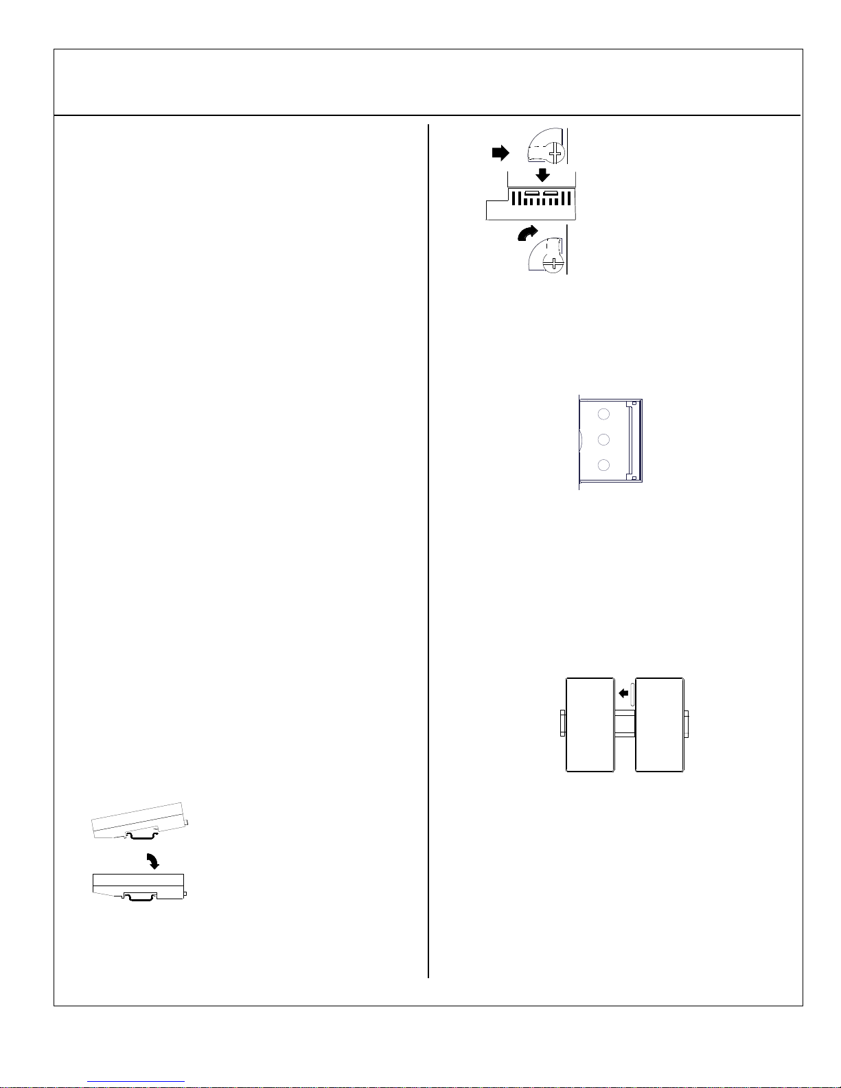
1. Install the NIU on the DIN Rail by simply clicking it into place.
Complete the power supply wiring as described in the installation
instructions provided with the Power Supply.
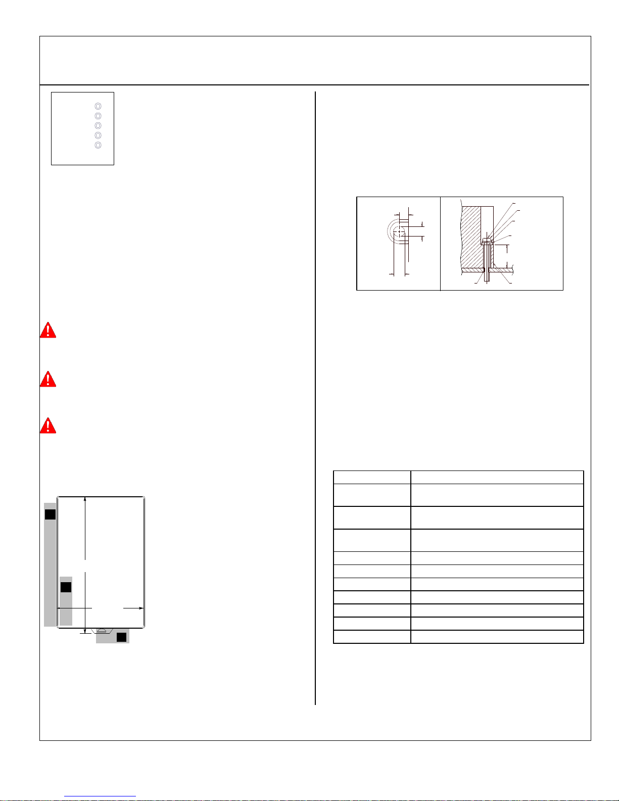
3. Adjust the rotary switches on the front of the NIU using a
2.44mm (3/32in) flat screwdriver. These switches, marked Node
Address X100, X10 and X1 select the hundreds, tens and units
digits of the network address. Select any valid address in the
range 1-125. Always cycle power to the NIU after changing the
switch settings.
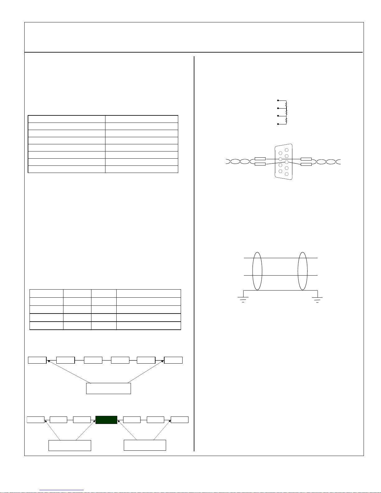
4. Connect the communications bus to the to the connector on
the front of the Network Interface Unit. (Refer to the heading
Bus Installation Guidelines for detailed bus installation
instructions.)
5. Remove the connector cover on the right-hand side of the
NIU. Do not discard this cover; you will need to install it on the
last carrier. It protects the connector pins from damage and
ESD during handling and use. Do not remove the connector
cover on the left-hand side.
6. Install additional modules by mounting modules on their
carriers and sliding them along the DIN rail to fully engage the
connectors in the sides of the carriers.
7. Power up the NIU. The modules in the I/O station will
automatically be configured, starting at slot 1 in each rack
including expansion racks. If an empty slot or faulted module is
encountered, auto-configuration for that rack stops. Auto-
configuration then skips to the next rack and continues until all
racks are configured.
Note: If the I/O station includes any additional power supplies,
those power supplies should be turned on at the same time.
8. Observe the Module LEDs. The LEDs indicate the presence of
power and show the operating mode and status of the NIU.