Important Product Information 3
GFK-1859B
Product Specifications
Ethernet IP address Any Valid IP Address
Default is 195.0.0.x, where x is selected on the rotary switches.
Ethernet network data rate 10Base-T or 100Base-TX, auto-negotiated
I/O data 1024 bytes maximum. Up to 512 bytes of inputs or 512 bytes of outputs.
Fault data 128 bytes maximum
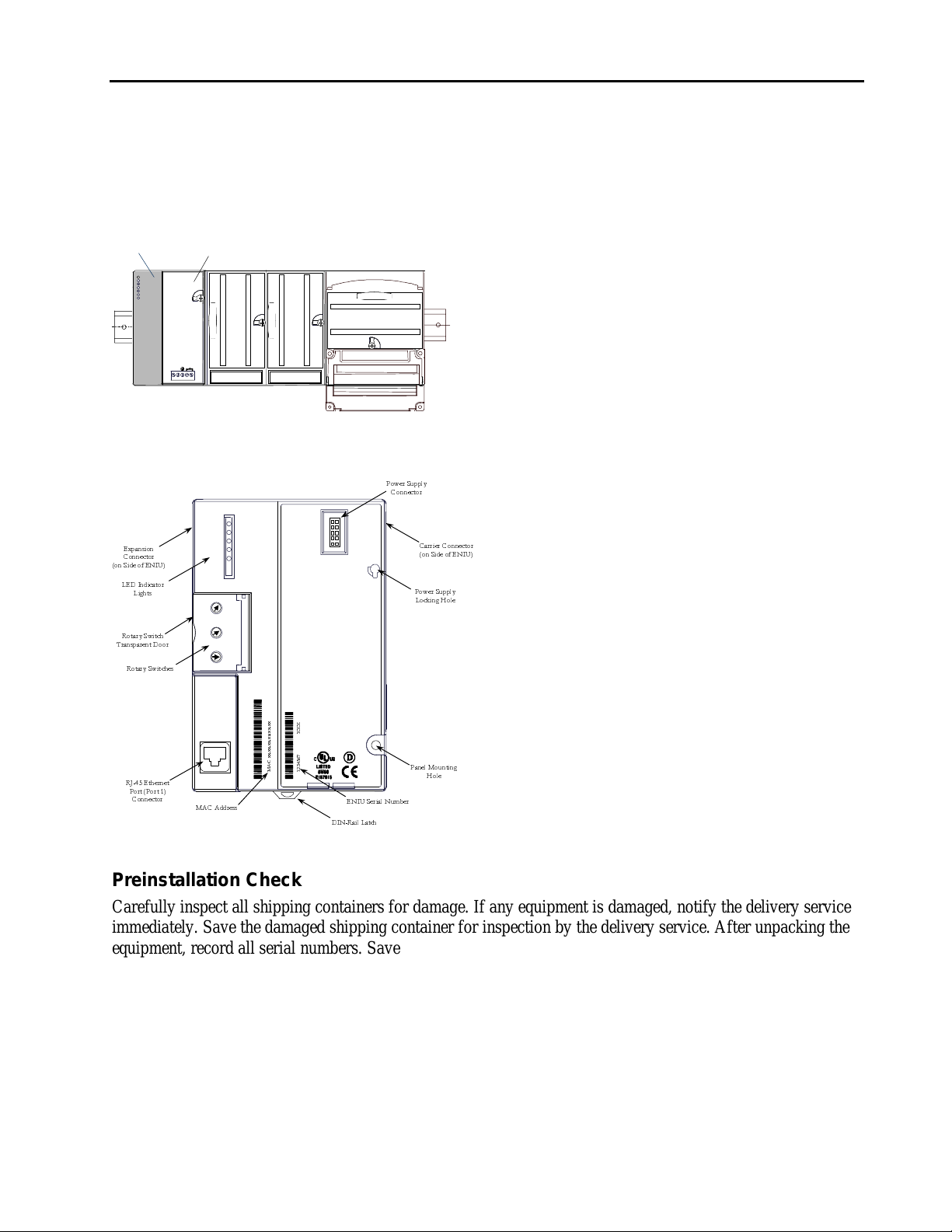
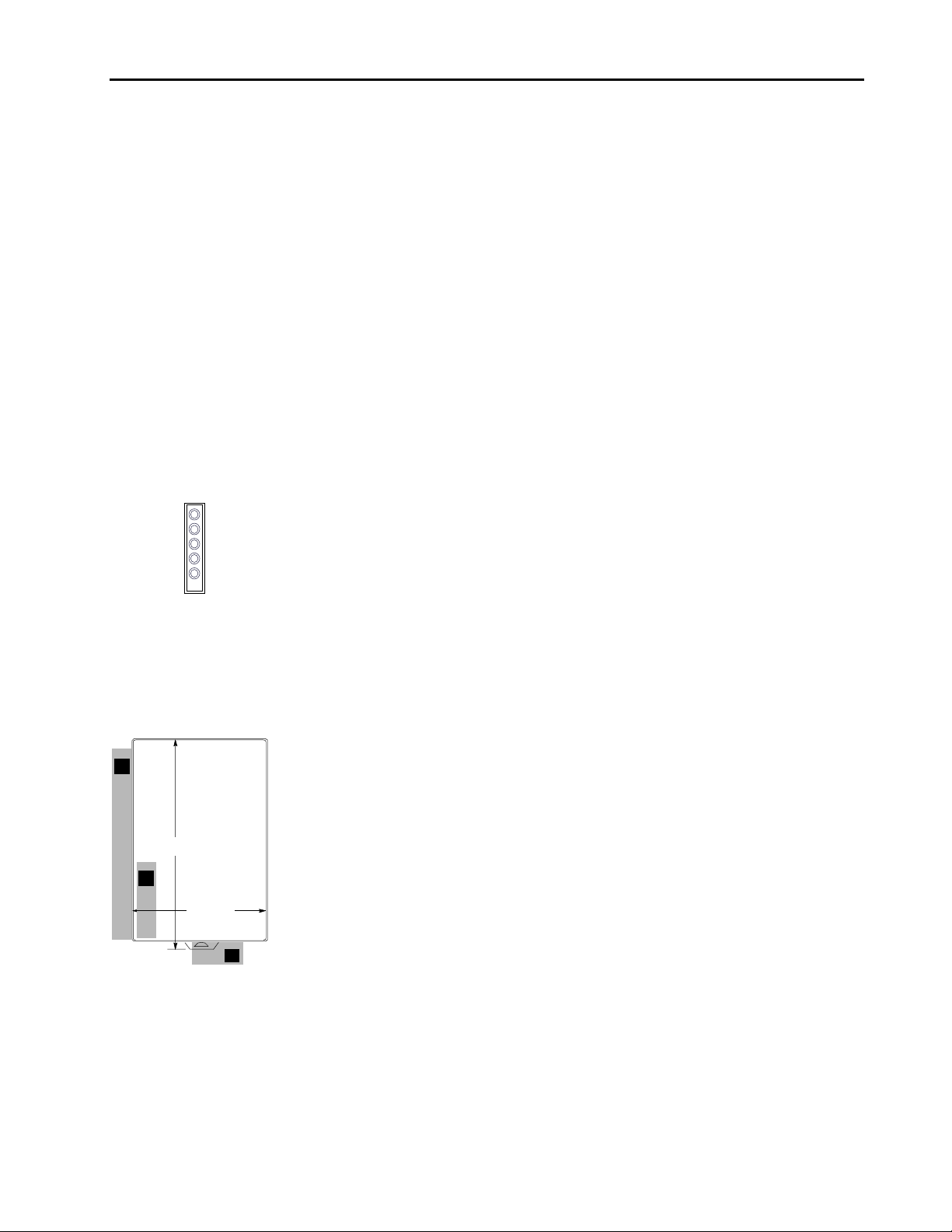
Indicators (5) Power LED indicates presence of input power
OK LED indicates health of the ENIU
Faults LED indicates presence of faults
LAN LED indicates health of Ethernet network
Stat LED solid green indicates Modbus connection present or receipt of EGD exchanges;
flashing Amber indicates invalid IP address
Number of I/O modules Release 1.0 supports 8 I/O modules and no expansion racks
Release 1.1 (and later releases) supports 64 I/O modules and 7 expansion racks.
Power Consumption +5V@175mA, +3.3V@425mA
Protocols Modbus Ethernet, Class 0 & 1 (all releases)
Ethernet Global Data (Release 1.1 and later releases)
High density analog modules Supported in Release 1.1 and later releases (requires VersaPro 2.0 or later, Remote I/O
Manager 2.0 or later, or Logic Developer PLC 2.10 or later to configure)
Hot Insertion for I/O modules Supported in Release 1.1 and later releases
Firmware Update Order kit Number 44A751424-G02 to update to Release 1.20
Features Introduced in Previous Release 1.1
1. Ethernet Global Data (EGD). Supports one produced exchange and one consumed exchange. All
configured input data are in the produced exchange, and all configured output data are in the consumed
exchange. EGD must be configured explicitly and is not available when the ENIU is autoconfigured.
2. Expansion I/O. Up to seven expansion racks may be connected to one ENIU with a total of 64 modules
supported.
3. Hot Insertion. I/O modules may be inserted or removed with power applied to the rack.
4. High Density Analog Modules. These may be used in an ENIU rack. However, VersaPro 2.0 or later is
required to configure these modules.
General Operation Notes
Power Cycle Conditions.
For both discrete and analog Output or Mixed modules, if the ENIU loses power but the Output or Mixed
modules do not lose power, the Hold Last State parameter does not work as might be expected. Upon ENIU
power loss, outputs configured for Hold Last State go to the Last State value on modules that still have power.
When power is restored to the ENIU, outputs go to the Default value. When communications are reestablished
and the ENIU receives a Write message, outputs go to the values in the ENIU’s Output Table.
Restrictions and Open Problems
Verify or Clear Operations Fail Occasionally
On rare occasions, a verify or clear operation from the programmer will fail. Retry to correct.