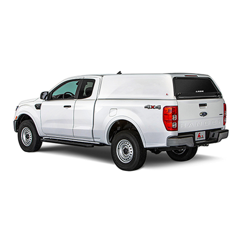
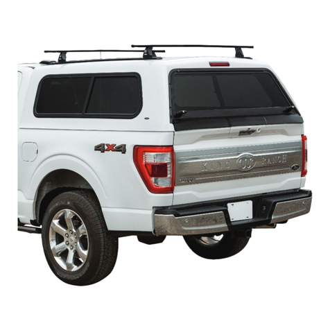
Leer CAB HIGH BED CAP Service manual

1
INSTALLATION INSTRUCTIONS
& OWNERS MANUAL
NOTICE D’INSTALLATION
ET GUIDE DU PROPRIÉTAIRE
INSTALACIÓN INSTRUCCIONES
& MANUAL DEL USUARIO
FORD F150
CAB HIGH
COMMERCIAL BED CAP
BOÎTE DE CAISSE COMMERCIALE ÉLEVÉE
DE CABINE
TAPA DE CAJA COMERCIAL PARA
CABINA ALTA
BY:
Part #217990
Pièce nº 217990
Pieza nº 217990

2
ENGLISH
TABLE OF CONTENTS
KEEP THESE INSTALLATION INSTRUCTIONS IN A CONVENIENT
LOCATION FOR FUTURE REFERENCE
Cab High Commercial Bed Cap Components .............................................................................3
Cap Installation Instructions.....................................................................................................4
Placing The Cap On The Truck...................................................................................................5
Secure Cap To Truck.................................................................................................................6
Wiring Harness Components .................................................................................................7-9
Final Inspection........................................................................................................................9
Removing Your Truck Cap .........................................................................................................9
Toolbox .............................................................................................................................10 – 11
Service Parts......................................................................................................................12-13
Limited Warranty.................................................................................................................... 14
Caring For Your Truck Cap........................................................................................................15

ENGLISH
3
CHECKLIST:
q Keys
q Clamp Pack
q Wiring Harness
(See page 7)
q Front Bulkhead Seal
q Double Bulb Seal
FORD CAB HIGH COMMERCIAL
BED CAP COMPONENTS
UNPACK COMPONENTS AND INSPECT FOR MISSING OR DAMAGED ITEMS
PLEASE SELECT ONE:
q 5’5” FORD CAB HIGH COMMERCIAL BED CAP
q 6’5” FORD CAB HIGH COMMERCIAL BED CAP
q 8’ FORD CAB HIGH COMMERCIAL BED CAP
TOOLS NEEDED:
1/2” Box End Wrench
Socket Wrench
1/2” Socket
Power
Screwdriver
6” Nylon
Cable Ties
Torque
Wrench
Keys
Utility
Knife
Double Bulb Seal Front Bulkhead D-Seal Clamp Pack

4
ENGLISH
INSTALLATION
INSTRUCTIONS
OPEN THE TRUCK TAILGATE AND CLEAN TRUCK BED RAILS
BEFORE YOU INSTALL
• We recommend using safety glasses
during installation.
• Keep truck tailgate down at all times
during assembly.
• Cap installation or removal requires four
people or use of a forklift.
• Read all instructions thoroughly before
installing cap.
INSTALLING CAP
(FOUR PEOPLE OR FORKLIFT REQUIRED)
1. Clean bedrails, top of bulkhead, rear truck
window and front window of cap with
50/50 isopropyl alcohol and a clean cloth.
2. Starting at the drivers side rear of the cap,
apply the double bulb seal 5/8” from the
outside cap edge in a straight line toward
the front (Fig A).
3. Repeat on the passengers side from rear
to front.
4. Apply the double bulb seal to the front
underside of the cap, ush against both
the drivers and passengers side double
bulb seal (Fig B).
Fig. A Starting at the driver side rear, apply the double bulb seal
5/8” from the outside cap edge in a straight line toward the front.
Fig. B. Apply the bulkhead seal to the front underside of the cap,
butting up to both the driver and passenger side double bulb seal.
Scan to See
Installation
Videos

ENGLISH
5
1. Open truck tailgate and rear door of cap.
2. (a) If using a forklift, be cautious of windows and lights while putting forklift about half-way into the cap
to ensure proper support. Place carefully on the truck.
(b) If using (4) four people, have one person at each corner of the cap. Being very careful of pinch-points
and vehicle nish, place cap on truck. (Fig. 4)
3. Square cap on bed from side to side and front to back. Align with truck bed.
4. Close the truck tailgate and rear cap door. Check t and function of door, handle, and seals.
5. Door skirt should seal against truck tailgate. Check front of truck cap – cap should not come into
contact with truck cab.
6. Adjust as necessary for proper t. (Fig. 5 & 6)
PLACING THE CAP
ON THE TRUCK
Fig. 4 Fig. 5
Fig. 6
Ladder Rack
Capacity
50 lbs. / 22.68 kg
Capacité de poids
du support d'échelle
50 lbs. / 22,68 kg
Capacidad De Peso De
La Rejilla Para Escaleras
50 lbs. / 22.68 kg

6
ENGLISH
Torque
Wrench
1. Place rear clamps 10” from rear of truck
bed; front clamps 5” from front of truck
bed on both sides of the truck.
2. Tighten clamps with a
Torque Wrench to
80 +/- 5 inch-lbs.
(6.7 +/- 0.4 foot-lbs.)
3. Clamps should be checked
periodically, and re-torqued
if needed.
Fig. 7
SECURE CAP TO TRUCK
Fg. 8
Fg. 9

ENGLISH
7
WIRING INSTRUCTIONS FORD CAB HIGH COMMERCIAL BED CAP
CHECKLIST
q 6” Nylon Cable Ties
q 1-Pin Aptiv Connector
q 2-Pin Molex Connector (3)
q Battery Harness
q Fuse Box Harness
q Stop Logic Harness
q 2-Pin T-Harness (3)
q Mini Zip Tie Adhesive Mounts (4)
Fig. 3
Fig. 1
Fig. 2
TPA
CPA
Fig. 4
Fig. 5
Fig. 6
Fig. 7
PLEASE FOLLOW THESE STEPS IN PROPER SEQUENCE
Steps 1-3 are done UNDER the hood
1. Place the ring terminal of the battery harness on the
positive terminal on the truck battery. Do not tighten
at this time. (Fig. 1)
2. Route the battery wire harness from the truck battery,
following the main truck wiring harness to the driver
side tailgate area.
3. Secure the battery harness with zip ties as you go.
Steps 4-8 are done from INSIDE the bed
4. Remove driver side taillight using an 8mm wrench.
5. Disconnect vehicle harness to taillights on
driver side. (Fig. 5)
6. Install appropriate tailgate intercept harness between
vehicle taillight harness and taillight. (Fig. 6)
Push all connectors together until click is heard.
This will lock the connectors together.
7. Repeat steps 4, 5 & 6 for passenger side.
8. Locate the access hole on the driver side rear of the
truck bed and pop out the cover. Feed the terminal
end of the fuse box harness down below the truck bed
through the access hole until the harness extends
below the truck fender. (Fig. 7)
Steps 9-15 are done from UND ER the truck
9. From the bottom of the driver side truck bed, feed the
driver side stop logic harness circuit (shorter circuit
with yellow & black wires) up into the taillight cavity.
(Fig 4.)
*Note: Make sure the harnesses follow the vehicle
taillight harness.
6” Nylon
Cable Ties
Fuse
Box
Harness
Battery
Harness
(4) Mini
Zip Tie
Adhesive
Mounts
Stop Logic
Harness
1-Pin Aptiv
Connector
(3) 2-Pin
Molex
Connector
WIRING HARNESS COMPONENTS
(3) 2-Pin
T-Harness
Scan For
Installation Videos

8
ENGLISH
PLEASE FOLLOW THESE STEPS IN PROPER SEQUENCE
10. Install the 2-pin Molex connector & the 1-pin Aptiv
connector on the Fuse Box Harness.
• Red/white wire into Molex connector pin 1. (Fig. 2)
• Black into Molex connector pin 2.
• Make sure all wires are in place and pull back lightly
to ensure that the wires are secure.
• Push in the white Terminal Position Assurance (TPA)
until it clicks. (Fig. 3)
11. Connect 2-pin Molex connector & 1-pin Aptiv
connector from step 10 to Stop Logic Harness.
(Fig. 8)
12. Plug Battery Harness into the Stop Logic Harness.
(Fig. 9)
13. Coil up all excess wires into the taillight cavity, and
secure with zip ties to the vehicle taillight harness.
14. Feed passenger side Stop Logic Harness circuit (long
circuit with green & black wires) across the rear of
the truck. Avoid any areas that get hot, that move,
or are sharp. Use provided zip ties to secure where
needed.
15. From the bottom of the passenger side truck bed, feed
the passenger side Stop Logic Harness circuit up into
the taillight cavity. (Fig. 4)
* Note: Make sure the harness exits out the same opening
as the vehicle taillight harness.
Steps 16-18 are done from INSIDE the truck bed
16. Install 2-pin Molex connector on the passenger side
Stop Logic Harness Circuit. (Fig. 10)
• Green into pin 1.
• Black into pin 2.
• Make sure both wires are in place and pull back
lightly to ensure that the wires are secure.
• Press in TPA until it clicks.
17. Connect the 2-pin Molex connector from step 16 into
the 2-pin Molex connector from the T-Harness used
in step 7. (Fig. 11)
18. Install 2-pin Molex connector on the driver side Stop
Logic Harness circuit. (Fig. 12)
• Yellow into pin 1.
• Black into pin 2.
• Make sure both wires are in place and pull back
lightly to ensure that the wires are secure.
• Press in TPA until it clicks.
Fig. 10
Fig. 11
WIRING INSTRUCTIONS
CAB HIGH COMMERCIAL BED CAP
Fig. 12
Fig. 8
Fig. 9

ENGLISH
9
Fig. 13
19. Connect the 2-pin Molex connector from step 18 in the 2-pin Molex connector
from the T-harness used in step 6. (Fig. 13)
20. Reinstall taillights
21. Tighten the nut securing battery harness terminal from Step 1.
Test System
22. Tube light on/off (vehicle must be on)
23. Center High Mounted Stop Light (CHMSL) - Turn vehicle on
*Make sure surroundings are clear before performing these tests.
• Step on Brake – CHMSL ON
• Left Turn w/ Brake – CHMSL ON
• Left Turn w/out Brake – CHMSL OFF
• Right Turn w/ Brake – CHMSL ON
• Right Turn w/out Brake – CHMSL OFF
• Hazards – CHMSL FLASHES
• Reverse w/ Brake – CHMSL ON
• Reverse w/out Brake – CHMSL OFF
24. Test proper operation of automatic tailgate for trucks with this feature.
WIRING INSTRUCTIONS
CAB HIGH COMMERCIAL BED CAP
PLEASE FOLLOW THESE STEPS IN PROPER SEQUENCE
REMOVING YOUR TRUCK CAP
4 PEOPLE OR FORKLIFT REQUIRED
1. Loosen and remove clamps on both sides. Keep clamps.
2. Disconnect wiring at bottom of fuse box. Leave cap harness in place.
3. Carefully lift and remove the cap from truck bed.
• NOTE: Be careful not to damage the truck cab, bed, or cap. It is recommended to replace the seal
before next installation.
FINAL INSPECTION
1. Assure all mounting clamps are tight.
2. Check rear door operation.
3. Check passenger and driver side window operation.
4. Check lighting including interior cap lights and third brake light.
5. If equipped with Thule EVO Square Bar Rack System, secure in accordance with instructions.

10
ENGLISH
TOOLBOX
50 lbs. / 22.68 kg
per tool box
(100 lbs. total
for bed cap)
50 lb. / 22,68 kg par
boîte à outils
(100 lb. total
pour le plateau)
50 libras. / 22.68 kg por
caja de herramientas
(100 libras en total para
la tapa de la plataforma)
Capacité de
poids de la
boîte à outils
Tool Box
Weight
Capacity
Capacidad De
Peso De La Caja
De Herramientas
Part #220975

ENGLISH
11
SERVICE PARTS LIST
5ft. 5 in. FORD CAB HIGH COMMERCIAL BED CAP
PART # DESCRIPTION
139156 FRONT WINDOW
218350 READ DOOR ASSEMBLY WITH SECURITY SCREEN
114669 REAR DOOR GAS PROP
214317 DOOR SKIRT
206036 REAR WINDOW
207705 20” TUBE LIGHT
207706 42” TUBE LIGHT
132413 DRIVER SIDE DOOR
219620 PASSENGER SIDE DOOR
219621 SIDE DOOR GAS PROP
6ft. 5 in. FORD CAB HIGH COMMERCIAL BED CAP
PART # DESCRIPTION
200858 REAR DOOR D SEAL
119513 LADDER RACK END CAP
212853 INSTALL KIT
213307 THIRD BRAKE LIGHT
218348 WIRE HARNESS KIT
139156 FRONT WINDOW
218350 READ DOOR ASSEMBLY WITH SECURITY SCREEN
114669 REAR DOOR GAS PROP
214317 DOOR SKIRT
206036 REAR WINDOW
207705 20” TUBE LIGHT
207706 42” TUBE LIGHT
132417 DRIVER SIDE DOOR
219622 PASSENGER SIDE DOOR
219623 SIDE DOOR GAS PROP
200858 REAR DOOR D SEAL

12
ENGLISH
8 ft. FORD CAB HIGH COMMERCIAL BED CAP
PART # DESCRIPTION
139156 FRONT WINDOW
218350 READ DOOR ASSEMBLY WITH SECURITY SCREEN
114669 REAR DOOR GAS PROP
214317 DOOR SKIRT
206036 REAR WINDOW
207705 20” TUBE LIGHT
207706 42” TUBE LIGHT
132421 DRIVER SIDE DOOR
219624 PASSENGER SIDE DOOR
219625 SIDE DOOR GAS PROP
200858 REAR DOOR D SEAL
119513 LADDER RACK END CAP
212854 INSTALL KIT
213307 THIRD BRAKE LIGHT
218348 WIRE HARNESS KIT
213138 FUSE BOX
6ft. 5 in. FORD CAB HIGH COMMERCIAL BED CAP, CONTINUED
PART # DESCRIPTION
119513 LADDER RACK END CAP
212853 INSTALL KIT
213307 THIRD BRAKE LIGHT
218348 WIRE HARNESS KIT
SERVICE PARTS LIST

ENGLISH
13
LIMITED
WARRANTY
All Ford part numbers provided by LEER®Group are warranted to be free from defects in materials or
workmanship on products properly installed per the installation instructions provided with the product.
This warranty covers repair or replacement of any defective product at no charge during the applicable
warranty period listed below. Labor for replacement or service of defective product is not paid or
reimbursed by LEER®Group.
WARRANTY PERIOD
USA
Product which appears on New Vehicle Monroney Label (window sticker)
Coverage which matches new vehicle warranty – Ford 3 years or 36,000 miles, whichever
comes rst; Lincoln 4 years or 50,000 miles, whichever comes rst.
Part purchased and installed during or after the original vehicle warranty
Whichever of the following options provides the greater benet to the customer:
1.) 2 years / unlimited miles or 2.) The remainder of the new vehicle warranty
OUTSIDE USA
Product which appears on New Vehicle Monroney Label (window sticker)
Coverage which matches new vehicle warranty – Ford 3 years or 60,000 kilometers, whichever
comes rst; Lincoln 4 years or 80,000 kilometers, whichever comes rst.
Part purchased and installed during or after the original vehicle warranty
Whichever of the following options provides the greater benet to the customer:
1.) 2 years /unlimited kilometers or 2.) The remainder of the new vehicle warranty
This limited warranty does not cover any damage, defect, or malfunction caused by misuse, abuse,
accident, improper installation, modication, or improper or lack of maintenance. Incidental and
consequential damages are not recoverable under this warranty. This warranty offers you specic legal
rights. You may have additional or other rights as which vary from state to state or province
to province.
If you experience a warranty issue with this product, please visit your Ford Dealer. If the repair is covered
by the warranty above and completed by the dealership, labor is also covered by Ford – Ford Warranty and
Policy – Section 3.
Please note that LEER®Group has replacement component parts available to assist consumers and
dealers to resolve warranty and non-warranty issues as quickly as possible.
NOTE TO DEALER
Ford Dealers should contact LEER®Group by email:
Fordcustomerservice@truckgroup.com
For technical assistance call 1-844-756-4247
NOTE TO OWNER
Ford truck owners should contact their Ford Dealer with any questions.

14
ENGLISH
CARING FOR
YOUR TRUCK CAP
TAKE A MOMENT TO REVIEW THE FOLLOWING CARE AND MAINTENANCE INSTRUCTIONS TO KEEP YOUR
TRUCK CAP PRODUCT LOOKING ITS BEST AND PERFORMING SAFELY
Your Ford brand product has been nished with premium-grade automotive paint.
Proper maintenance of this new nish will be rewarded with a long-lasting beautiful appearance. The
following guidelines are provided for you:
• Avoid wiping or waxing your cap for 90 days and avoid commercial or high-pressure car washes for
90 days. This gives the fresh paint nish the maximum time to cure completely.
• Do not wipe your cap with a dry cloth.
• Do not spill chemicals such as anti-freeze or coolant on the nish.
• Do not scrape ice or snow from the nish.
• Do not use polishes not formulated for clear-coat nishes.
• Do not add exterior wraps* or stickers until the cap has been installed for 48 hours.
• After 90 days, wash and wax your cap regularly with a product designed to preserve and protect
painted nish. Ask your Ford Dealer for product recommendations. Make sure to wash your cap in a
shaded area using cool water and a mild detergent.
• Do not subject the windows of your cap to the direct force of high-pressure commercial car
washes or pressure washers. Windows are not warranted against leaks under the pressure of
such equipment.
*Exterior wraps and stickers applied incorrectly may void paint warranty.
MAINTENANCE RECOMMENDATIONS
Regular maintenance will keep your truck cap working well. Your Ford Dealer would
be happy to help you for a nominal fee.
1. Lubricate the door hinges and door lock(s) monthly with an oil-based lubricant. Do not use silicone or
petroleum distillate (WD40, etc.) spray lubricant on gas props. Caution: Do not get oil based lubricant
near any of the cap seals.
2. Check clamps for tightness monthly. Torque clamps to 80 +/- 5 inch-lbs, (6.7 +/- 0.4 foot-lbs). Clamps are
suitable for securing caps when properly installed. Ask your Ford Dealer if you have any questions about the
attachment process.
IMPORTANT SAFETY TIPS
• Do not drive with any of the cap doors open.
• Do not use the product for passenger occupancy
while the vehicle is in motion or while the
engine is running.
• Contact your auto insurance company to make
them aware you have added a truck cap to
your vehicle.
Ladder Rack
Capacity
50 lbs. / 22.68 kg
Capacité de poids
du support d'échelle
50 lbs. / 22,68 kg
Capacidad De Peso De
La Rejilla Para Escaleras
50 lbs. / 22.68 kg
50 lbs. / 22.68 kg
per tool box
(100 lbs. total
for bed cap)
50 lb. / 22,68 kg par
boîte à outils
(100 lb. total
pour le plateau)
50 libras. / 22.68 kg por
caja de herramientas
(100 libras en total para
la tapa de la plataforma)
Capacité de
poids de la
boîte à outils
Tool Box
Weight
Capacity
Capacidad De
Peso De La Caja
De Herramientas
Part #220975

FRANÇAIS
15
TABLE DES MATIÈRES
CONSERVER CETTE NOTICE D’INSTALLATION DANS UN ENDROIT
PRATIQUE POUR CONSULTATION FUTURE
Composants de boîte de caisse commerciale élevée de cabine................................................ 17
Instructions d’installation de boîte........................................................................................... 18
Mise en place de la boîte sur la camionnette............................................................................. 19
Fixation de la boîte sur la camionnette.................................................................................... 20
Composants de faisceau de câblage...................................................................................21-23
Contrôle nal...........................................................................................................................23
Dépose de votre boîte de camionnette.....................................................................................23
Boîte à outils ..................................................................................................................... 24-25
Nomenclature des piéces de recharge............................................................................... 26-27
G-arantie limitée .....................................................................................................................28
Entretien de votre boîte de camionnette..................................................................................29

FRANÇAIS
16
LISTE DE CONTRÔLE:
q Clés
q Paquet de brides
q Faisceau de câblage
(Voir page 22)
q Joint de la paroi avant
q Double joint à bulbe
COMPOSANTS DE BOÎTE DE CAISSE
COMMERCIALE ÉLEVÉE DE CABINE
FORD
DÉBALLER LES COMPOSANTS; VÉRIFIER QU’ILS SONT INTACTS ET QU’IL N’EN MANQUE AUCUN
SÉLECTIONNER L’UN DES
ÉLÉMENTS SUIVANTS:
q BOÎTE DE CAISSE COMMERCIALE ÉLEVÉE 5’5”
DE CABINE FORD
q BOÎTE DE CAISSE COMMERCIALE ÉLEVÉE 6’5”
DE CABINE FORD
q BOÎTE DE CAISSE COMMERCIALE ÉLEVÉE 8’
DE CABINE FORD
Clés
Double joint à bulbe Joint de la paroi avant Paquet de brides
OUTILS REQUIS:
Clé polygonale 1/2 po
Clé à douille
Douille 1/2 po
Tournevis
électrique
Attaches
autobloquantes
en nylon 6”
Clé
dynamométrique Couteau à lame
rétractable

FRANÇAIS
17
NOTICE D’INSTALLATION
OUVRIR LE HAYON, PUIS NETTOYER LES RAILS DE CAISSE
PRÉLIMINAIRES
• Nous recommandons de porter des
lunettesde sécurité pendant l’installation.
• Laisser le hayon ouvert à tout moment
pendant le montage.
• Quatre personnes ou un chariot à fourche
sont nécessaires à la pose ou à la dépose
de la boîte de camionnette.
• Lire attentivement toutes les instructions
avant d’installer la boîte.
INSTALLATION DE LA BOÎTE
(4 PERSONNES OU UN CHARIOT À FOURCHE NÉCESSAIRES)
1. Avec un linge propre imbibé d’une solution d’alcool
isopropylique 50/50, nettoyer les rails de caisse,
le rebord de la paroi avant, la lunette arrière de la
cabine et la fenêtre avant de la boîte.
2. À partir de l’arrière, côté conducteur, appliquer le
joint double de bulbe de 5/8” sous le bord
extérieur de la boîte, en ligne droite vers
l’avant (Fig A).
3. Répéter le processus du côté passager, de l’arrière
à l’avant.
4. Appliquer le joint double de bulbe sous le bord
avant de la boîte, au ras des joints doubles de
bulbe latéraux côtés conducteur et passager
(Fig B).
Fig. A À partir de l’arrière, côté conducteur, appliquer le joint
double de bulbe de 5/8” sous le bord extérieur de la boîte, en ligne
droite vers l’avant.
Fig. B. Appliquer le joint de cloison sous le bord avant de la boîte,
au ras des joint doubles de bulbe, côtés conducteur et passager.
Scanner pour
regarder
les vidéos
d’installation

FRANÇAIS
18
1. Ouvrir le hayon de la camionnette et la porte arrière de la boîte.
2. (a) Si vous utilisez un chariot élévateur, faites attention aux fenêtres et à l’éclairage tout en plaçant le
chariot élévateur à mi-chemin dans la boîte pour assurer un soutien adéquat. Placer avec précaution
sur la camionnette.
(b) Si la tâche est effectuée par quatre (4) personnes, placer chaque personne à chaque coin de la boîte.
En faisant très attention aux points de pincement et à la nition du véhicule, placer la boîte sur la
camionnette. (Fig. 4)
3. Centrer la boîte d’un côté à l’autre et d’avant en arrière. Aligner la boîte sur la caisse.
4. Fermer le hayon de la camionnette et la porte arrière de la boîte.
Véri er l’alignement et le jeu de la porte,
des poignées et des joints.
5. La semelle de porte doit fermer
hermétiquement le hayon de la camionnette.
Véri er l’avant de la boîte de la camionnette - la boîte ne doit pas toucher la cabine de la camionnette.
6. Recti er au besoin pour bien aligner la boîte sur la camionnette. (Fig. 5 et 6)
MISE EN PLACE DE LA BOÎTE
SUR LA CAMIONNETTE
Fig. 4
Ladder Rack
Capacity
50 lbs. / 22.68 kg
Capacité de poids
du support d'échelle
50 lbs. / 22,68 kg
Capacidad De Peso De
La Rejilla Para Escaleras
50 lbs. / 22.68 kg
Fig. 5
Fig. 6

FRANÇAIS
19
1. Placer les étriers à 10” de l’arrière et à 5” de
l’avant de la caisse, de chaque côté de la
camionnette.
2. Serrer les étriers avec une clé dynamométrique
à un couple de 80 +/- 5 po-lb.
(6,7 +/- 0,4 pd-lb.)
3. Vérier les étriers
périodiquement;
les resserrer au besoin.
Clé dynamométrique
Fig. 7
FIXATION DE LA BOÎTE SUR LA
CAMIONNETTE
Fg. 8
Fg. 9

FRANÇAIS
20
Fig. 3
Fig. 1
Fig. 2
TPA
CPA
Fig. 4
Fig. 5
Fig. 6
Fig. 7
COMPOSANTS DE FAISCEAU DE CÂBLAGE
LISTE DE CONTRÔLE
q Attaches autobloquantes en nylon 6”
q Connecteur Aptiv 1 broche
q Connecteur Molex 2 broches (3)
q Faisceau de batterie
q Faisceau du boîtier à fusibles
q Faisceau Stop Logic
q Faisceau en T 2 broches (3)
q Mini supports adhésifs pour
attaches de câbles (4)
Attaches
autobloquantes
en nylon 6”
Faisceau
du boîtier à
fusibles
Faisceau
Stop Logic
Connecteur
Aptiv 1 broche
Connecteur
Molex 2
broches (3)
Faisceau en T
2 broches (3)
Faisceau de
batterie
Mini supports
adhésifs pour
attaches de
câbles (4)
SUIVRE CES ÉTAPES DANS L’ORDRE
Suivre les instructions 1 à 3 EN DESSOUS du capot
1. Placer la cosse annulaire du faisceau de batterie sur la borne
positive de la batterie de la camionnette. Ne pas serrer à ce
moment-là. (Fig. 1)
2. Acheminer le faisceau de ls de la batterie depuis la batterie
de la camionnette, en suivant le faisceau de ls principal de
la camionnette vers la zone du hayon côté conducteur.
3. Fixer le faisceau de batterie avec les attaches au fur
et à mesure.
Suivre les instructions 4 à 8 À L’INTÉRIEUR de la caisse
4. Retirer le feu arrière côté conducteur à l’aide d’une clé
de 8 mm.
5. Débrancher le faisceau véhicule des feux arrière côté
conducteur. (Fig. 5)
6. Installer un faisceau d’interception de hayon approprié entre
le faisceau de feu arrière du véhicule et le feu arrière. (Fig. 6)
Enclencher tous les connecteurs jusqu’à ce qu’un clic se
fasse entendre.
Les connecteurs seront alors verrouillés.
7. Répéter les étapes 4, 5 et 6 côté passager.
8. Localiser le trou d’accès situé à l’arrière de la boîte de caisse,
puis ouvrir le couvercle. Faire passer l’extrémité de la borne
du faisceau de la boîte à fusibles sous la boîte de casse par
l’ori ce d’accès jusqu’à ce que le faisceau se déploie sous le
garde-boue de la camionnette. (Fig. 7)
Suivre les instructions 9 à 15 EN DESSOUS de la camionnette
9. Par le bas de la caisse côté conducteur, faire remonter le
faisceau Stop Logic côté conducteur (circuit court, avec ls
jaune et noir) dans la cavité du feu arrière. (Fig 4.)
*Remarque: Assurez-vous que les harnais suivent le harnais
des feux arrière du véhicule.
INSTRUCTIONS DE CÂBLAGE POUR
BOÎTE DE CAISSE COMMERCIALE
ÉLEVÉE DE CABINE FORD
Other manuals for CAB HIGH BED CAP
1
Table of contents
Languages:
Other Leer Automobile Accessories manuals

Leer
Leer 1LG0300000 User manual

Leer
Leer CAB HIGH BED CAP Service manual

Leer
Leer Velocity User manual

Leer
Leer PACE EDWARDS ULTRAGROOVE ELECTRIC User manual

Leer
Leer CAB HIGH SPORT BED CAP Service manual

Leer
Leer CAB HIGH PREMIUM BED CAP Service manual

Leer
Leer SR 250 Service manual

Leer
Leer 217988 Service manual

Leer
Leer HF650M User manual
Popular Automobile Accessories manuals by other brands

Kuda-Phonebase
Kuda-Phonebase 096480 Installation instruction

FABBRI PORTATUTTO
FABBRI PORTATUTTO 17516400 Assembly instructions

Front Runner
Front Runner LATF001 installation instructions

Panavise
Panavise Indash 75128-905 installation instructions

Thule
Thule 1170 instructions

Yakima
Yakima K386 Fitting instructions