VERSE EDGE 500 User manual

EN - User Man al
IT - Man ale Utente
DE - Ben tzerhandb ch
Ver. 1 .0
P
Pr
ro
of
fe
es
ss
si
io
on
na
al
lA
A
d
di
io
o
EDGE 500
Active Speakers


EDGE 500
- User Manual
EN - 1
CONTENTS
Important notes ........................................................................................................... 1
Overview ..................................................................................................................... 2
Controls and connections ............................................................................................ 3
Connection examples .................................................................................................. 5
Components, configuration and performances ............................................................ 8
Placement ................................................................................................................... 9
Usage suggestions .................................................................................................... 12
Technical specifications ............................................................................................. 13
Block diagram............................................................................................................ 14
IMPORTANT NOTES
LOOKING AFTER THE PRODUCT
•Never apply excessive force to the structures or controls (knobs, switches).
•Do not stress the speaker in transit or during use.
•Do not place the device close to heat sources, in damp or dusty places or close to
strong magnetic fields.
•When possible, do not place the speaker close to units which generate strong
interference, such as radio and TV sets, monitors, etc.
•Never insert objects or liquids of any kind inside the device, for any reason.
•Clean using a soft brush or an air jet only; never use detergents, solvents or alcohol.
•When disconnecting cables from sockets, always take hold of them by the connector
and not by the cable itself, and when winding take care to avoid knots or twisting.
•Do not expose the speaker to direct sunlight.
CONNECTING TO THE MAINS
•To avoid the risk of electric shock, do not make connections with wet hands.
•Make sure that the mains voltage is the same as that indicated on the control panel.
•Connect the speaker to a mains socket with earth contact.
CONNECTING TO A MIXER
•Always use good quality screened cables.
•Before making the connections, check that all the speakers you are about to connect
are switched off. You will avoid noisy, if not hazardous, signal peaks.
IN CASE OF MALFUNCTION
•In case of malfunction, contact only an authorised service centre.

User Manual - EDGE 500
EN - 2
PRESENTATION
EDGE 500 is an active speaker that combines
technology, experience and good taste in the ideal
combination of sound quality, power and user-
friendliness. It is equipped with 2 (two) 8" woofers
custom + 1" compression driver, 2 independent
signal processors for high/low frequencies .
The speaker is backed up by a digital signal
processing chain, 350W+65W biamplification and
meticulous sound engineering which ensures
impeccable results in terms of intelligible sound
reproduction, breadth and constancy of diffusion,
power and amplification precision.
The cabinet, in polypropylene with scratchproof
finish, is attractively styled and designed to make
the speaker easy to use and install in a variety of
positions, both on the ground and suspended.
The EDGE 500 is the ideal solution for all small
and medium-sized sound systems where it is
important to obtain the maximum sound coverage
with the smallest possible number of speakers.
TECHNOLOGY
AMPLIFIERS
The new digital technology totally changed the way a professional audio amplifier is
developed. No other way make possible to give great power and long term reliability.
Remarkable heat reduction and outstanding weight decrease make digital amplifier, that
equip VERSE EDGE 500, efficient, powerful and less heating.
The output stages of the amplifiers typically run at 95% efficiency, dissipating only 5% of
the input energy as heat. Moreover the efficiency doesn't depend on the output level,
and Since standard music has an average power density of 40% of the maximum level,
conventional amplifiers can easily generate 10 times more heat than VERSE ones for
the same volume of sound.
To grant reliability and durability, VERSE amplifiers are provided with short-circuit
protection, thermal protection with fan-speed control (that avoid temperature rising over
60° C) and amplifier disactivation system thus preventing amplifier breakdown if tempe-
rature rise to intolerable values. And also: protection circuit to cancel direct current
component, protection from ultrasonic components in input and output.
The I.T.P (Intelligent Thermal Protect) is warranty of perfect-working and long-lasting
speakers.

EDGE 500
- User Manual
EN - 3
PROCESSING
The processors include cross-over and pass-band filters, level compressors/limiters,
delay for the phase alignment of the system. The processors work automatically and are
conceived to assure the best condition of playback and safety.
In detail: each one of the two ways has his own limiter wich act on the equalizer section
and not – as usually happens – on the overall level only. This leaves – also when the
limiter acts – the sound nearly unchanged, because only the critic frequency region is
damped.
CONTROLS AND CONNECTIONS
1
2
3
4
58
7
6

User Manual - EDGE 500
EN - 4
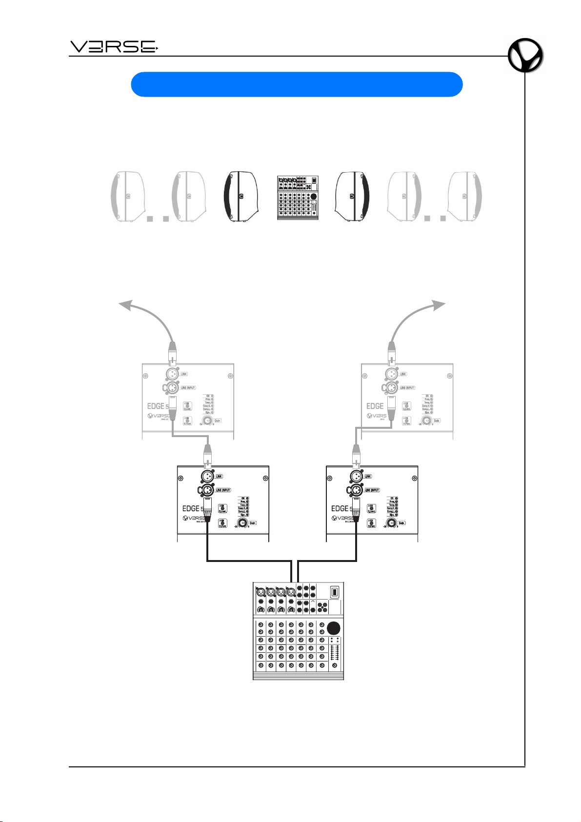
1. Link: sends on output the same signal coming from LINE INPUT connector. This
allow the cascade connection of different devices to the same sound source.
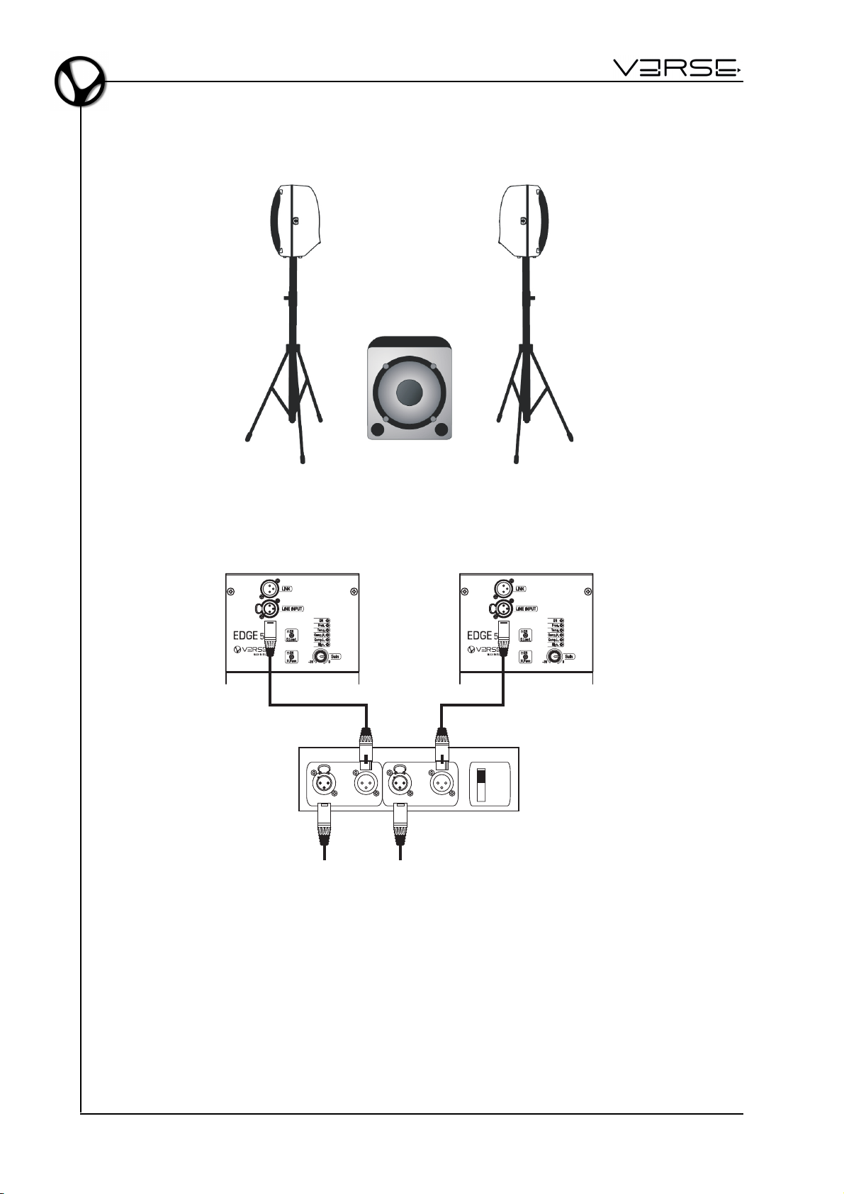
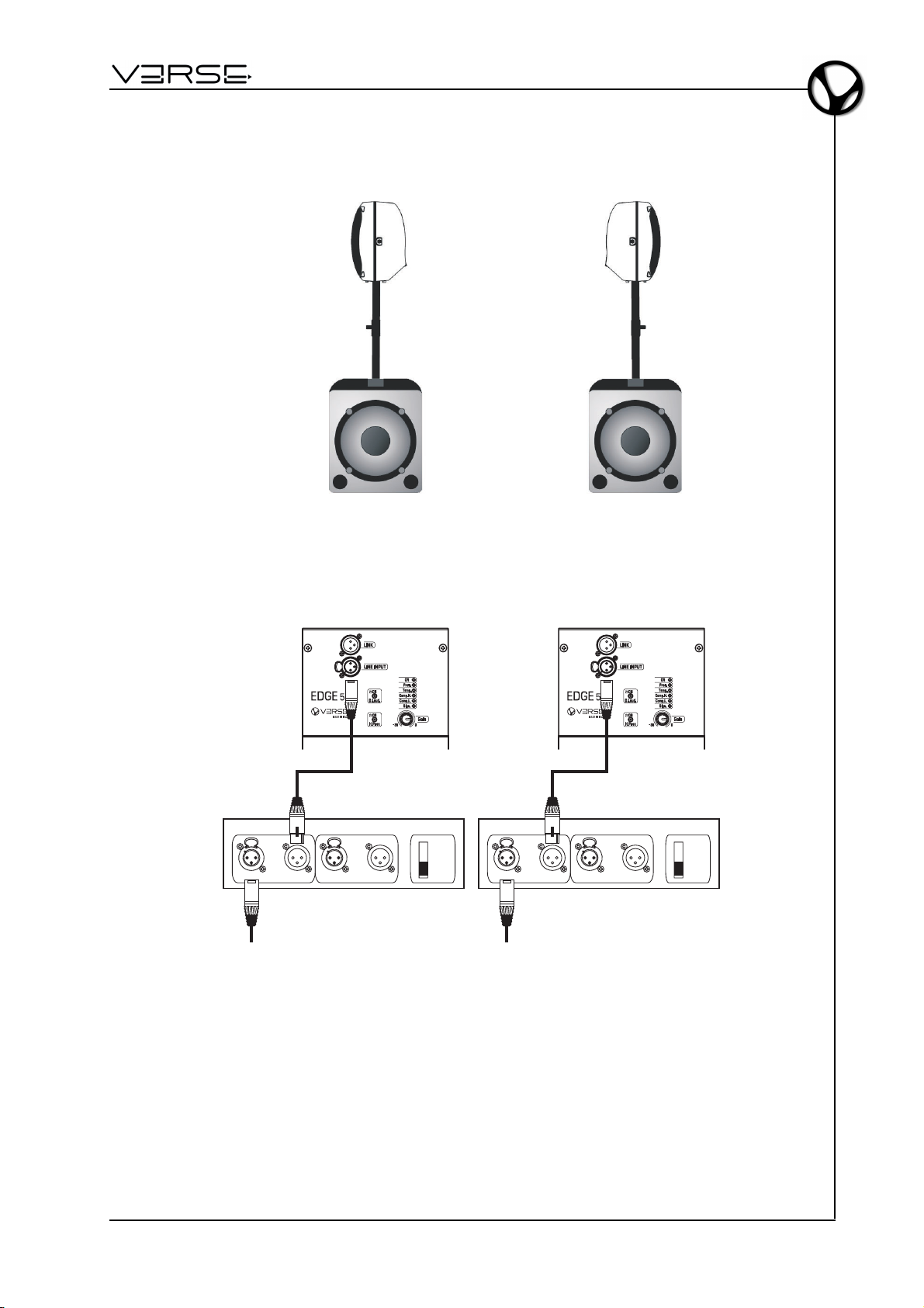
2. Line Input: balanced XLR socket for connection of the signal to be amplified.
3. D.Loud.: activates a dynamic equalization of the system, to compensate the natural
sensibility curve of the human ear, which is weaker on low and high frequencies,
when the sound volume is low. The equalization is dynamic, allowing to regulate
continously the amount, according to the signal level, fading away when the volumes
get to the highest levels.
4. H.Pass: activates a High-Pass filter, expressly made to join the speaker together
with a subwoofer. When this filter is turned off, the speaker behaves like a full-range
speaker, while when the filter is activated the speaker behaves like a "satellite" of a
subwoofer.
5. AC-IN: power supply cable socket. The socket is fitted with a fuse in a protected
casing. If the fuse needs changing, it is very important to proceed as follows:
- switch off the device;
- remove the power supply cable;
- access the fuse compartment by opening the cover with a screwdriver;
- replace the fuse with another having exactly the same specifications, T2A L 250V in
230 VAC version or - T4A L 250V in 120 VAC and 100 VAC versions;
- close the cover.
6. LEDs:
- ON: indicates that the speaker is On.
- Prot.: indicates that the internal amplifier switched to protection mode due to a fault
of the amplifier itself or of the connected speakers (please call the technical support).
- Temp.: indicates that the internal amplifier switched to protection mode due to
excessive heating. In this condition, the amplifier supply half the normal power.
Please reduce the input signal to allow the restore of normal load conditions.
- Comp. H.: indicates activity of the High frequency compressor. If the signal passes
over a safety threshold, the compressor guarantees a good quality playback without
acoustic distortion, damping the appropriate signal frequencies. The system operates
in total safety. If the LED is constantly On, there is an excess of signal. In this case,
please reduce the incoming signal level.
- Comp. L.: indicates activity of the Low frequency compressor. If the signal passes
over a safety threshold, the compressor guarantees a good quality playback without
acoustic distortion, damping the appropriate signal frequencies. The system operates
in total safety. If the LED is constantly On, there is an excess of signal. In this case,
please reduce the incoming signal level.
- Sign.: indicates that the signal is present.
7. Gain: to adjust the signal gain in the range from -35dB to 0dB.
8. POWER: switches the power on/off.

EDGE 500
- User Manual
EN - 5
CONNECTION EXAMPLES
MIXER + 2 (or more) EDGE 500 - STEREO
G
A
I
N
L
I
N
E
I
M
C
G
A
I
N
S
E
N
S
I
T
I
V
I
T
Y
L
I
N
E
G
A
I
N
L
I
N
E
I
M
C
G
A
I
N
S
E
N
S
I
T
I
V
I
T
Y
L
I
N
E
-10dB +10 -30 -50dB
G
A
I
N
L
I
N
E
I
M
C
G
A
I
N
S
E
N
S
I
T
I
V
I
T
Y
L
I
N
E
-10dB +10 -30 -50dB-10dB +10 -30 -50dB
G
A
I
N
L
I
N
E
I
M
C
G
A
I
N
S
E
N
S
I
T
I
V
I
T
Y
L
I
N
E
G
A
I
N
L
I
N
E
I
M
C
G
A
I
N
S
E
N
S
I
T
I
V
I
T
Y
L
I
N
E
-10dB +10 -30-50dB
G
A
I
N
L
I
N
E
I
M
C
G
A
I
N
S
E
N
S
I
T
I
V
I
T
Y
L
I
N
E
-10dB +10 -30-50dB-10dB +10 -30 -50dB
G
A
I
N
L
I
N
E
I
M
C
G
A
I
N
S
E
N
S
I
T
I
V
I
T
Y
L
I
N
E
G
A
I
N
L
I
N
E
I
M
C
G
A
I
N
S
E
N
S
I
T
I
V
I
T
Y
L
I
N
E
-10dB +10 -30 -50dB
G
A
I
N
L
I
N
E
I
M
C
G
A
I
N
S
E
N
S
I
T
I
V
I
T
Y
L
I
N
E
-10dB +10 -30 -50dB-10dB +10 -30 -50dB
G
A
I
N
L
I
N
E
I
M
C
G
A
I
N
S
E
N
S
I
T
I
V
I
T
Y
L
I
N
E
G
A
I
N
L
I
N
E
I
M
C
G
A
I
N
S
E
N
S
I
T
I
V
I
T
Y
L
I
N
E
-10dB +10 -30 -50dB
G
A
I
N
L
I
N
E
I
M
C
G
A
I
N
S
E
N
S
I
T
I
V
I
T
Y
L
I
N
E
-10dB +10 -30 -50dB-10dB +10 -30 -50dB
G
A
I
N
L
I
N
E
I
M
C
G
A
I
N
S
E
N
S
I
T
I
V
I
T
Y
L
I
N
E
G
A
I
N
L
I
N
E
I
M
C
G
A
I
N
S
E
N
S
I
T
I
V
I
T
Y
L
I
N
E
-10dB+10 -30 -50dB
G
A
I
N
L
I
N
E
I
M
C
G
A
I
N
S
E
N
S
I
T
I
V
I
T
Y
L
I
N
E
-10dB+10 -30 -50dB-10dB+10 -30 -50dB
G
A
I
N
L
I
N
E
I
M
C
G
A
I
N
S
E
N
S
I
T
I
V
I
T
Y
L
I
N
E
G
A
I
N
L
I
N
E
I
M
C
G
A
I
N
S
E
N
S
I
T
I
V
I
T
Y
L
I
N
E
-10dB+10 -30 -50dB
G
A
I
N
L
I
N
E
I
M
C
G
A
I
N
S
E
N
S
I
T
I
V
I
T
Y
L
I
N
E
-10dB+10 -30 -50dB-10dB+10 -30 -50dB
G
A
I
N
L
I
N
E
I
M
C
G
A
I
N
S
E
N
S
I
T
I
V
I
T
Y
L
I
N
E
G
A
I
N
L
I
N
E
I
M
C
G
A
I
N
S
E
N
S
I
T
I
V
I
T
Y
L
I
N
E
-10dB+10 -30-50dB
G
A
I
N
L
I
N
E
I
M
C
G
A
I
N
S
E
N
S
I
T
I
V
I
T
Y
L
I
N
E
-10dB+10 -30-50dB-10dB+10 -30-50dB
G
A
I
N
L
I
N
E
I
M
C
G
A
I
N
S
E
N
S
I
T
I
V
I
T
Y
L
I
N
E
G
A
I
N
L
I
N
E
I
M
C
G
A
I
N
S
E
N
S
I
T
I
V
I
T
Y
L
I
N
E
-10dB+10 -30-50dB
G
A
I
N
L
I
N
E
I
M
C
G
A
I
N
S
E
N
S
I
T
I
V
I
T
Y
L
I
N
E
-10dB+10 -30-50dB-10dB+10 -30-50dB
LEFT RIGHT
Left Out Right Out
MIXER

User Manual - EDGE 500
EN - 6
1 ACTIVE SUB + 2 EDGE 500 - STEREO
Input Link Input Link
Left/Mono Right
Stereo
Mono
ACTIVE SUB-WOOFER
LEFT RIGHT
Left
Source
Signal
Right
Source
Signal

EDGE 500
- User Manual
EN - 7
2 ACTIVE SUB + 2 EDGE 500 - STEREO
LEFT RIGHT
Input Link Input Link
Left/Mono Right
Stereo
Mono
ACTIVE SUB-WOOFER
Left
Source
Signal
Input Link Input Link
Left/Mono Right
Stereo
Mono
ACTIVE SUB-WOOFER
Right
Source
Signal

User Manual - EDGE 500
EN - 8
COMPONENTS, CONFIGURATION AND PERFORMANCES
The diffusion section uses high efficiency custom devices, engineered in the special
configuration: 2 x 8” woofer + 1" compression driver.
The connection of these elements offers significant advantages for both the reliability
and the acoustic performance, especially in the reproduction of the vocal range.
Some examples:
a. The double 8" woofer reduces the interacting
masses by 30% compared to the classic
configuration with a single 12" speaker. This
leads to a higher acceleration factor (faster
response to the transients), a wider
extension toward high frequencies and
therefore a better acoustic continuity among
high/low components of the system.
b. Using a 1" HF driver, made following the last
generation technologies and provided with
a polyestere diaphragm, causes a much
more efficient high frequencies (106 dB)
transduction, a wider frequency extension,
a better acceleration factor and a higher
reliability.
c. The HF driver is assembled on a elliptical
wave trumpet, designed for being free from
acoustic resonance and, at the same time,
for being characterised by a wide dispersion
angle, an excellent quality of the diffusion – even out of the axis – and a special
intelligibility of medium-high and high frequencies range. All these characteristic
provide an acoustic coherence that allows: - The audience: to enjoy the same
sound quality anywhere on the stand. - The performers: to maintain a constant
hearing perception, whenever the loudspeaker is placed vertically, for monitor use,
etc.

EDGE 500
- User Manual
EN - 9
PLACEMENT
The design and mechanical fittings of the EDGE 500 cabinet make it easy to use and
install the system to suit specific requirements :
- on the floor: vertical, horizontal, or tilted in monitor-mode
- suspended: on a stand, wall-mounted or hung from technical structures.
The special component layout ensures that sound diffusion is always impeccable.

User Manual - EDGE 500
EN - 10
POLE AND TRIPOD SAFETY RECOMMENDATION
This manual assumes that the owners and/or users of a VERSE System are
knowledgeable and experienced in the areas of Pole and Tripod use with loudspeaker
systems.
The suspension of large, heavy objects on Pole or Tripod in public places is subject to
numerous laws and regulations at the national/federal, state/provincial, and local levels,
that are not addressed in this manual.
However, the user must assume responsibility for making sure that use of any VERSE
system, its components and all the stands and poles and associated hardware in any
particular circumstance or venue conforms to all applicable laws and regulations in force
at the time.
WHEN USING STANDS OR POLES, BE SURE TO OBSERVE THE FOLLOWING
PRECAUTIONS.
CHECK THE STAND OR POLE SPECIFICATION TO BE CERTAIN THE DEVICE IS
DESIGNED TO SUPPORT THE WEIGHT OF THE SPEAKER. OBSERVEALL SAFETY
PRECAUTIONS SPECIFIED BY THE MANUFACTURER. MAKE SURE THAT THE
SURFACE ON WHICH THE SYSTEM IS TO BE STACKED IS FLAT, STABLE AND
SOLID.
ROUTE CABLES SO THAT PERFORMERS, PRODUCTION CREW, AND AUDIENCE
WILL NOT TRIP AND TOPPLE THE SPEAKERS.
INSPECT THE STAND (OR POLE AND ASSOCIATED HARDWARE) BEFORE EACH
USEAND DO NOT USE EQUIPMENT WITH WORN, DAMAGED, OR MISSING PARTS.
DO NOTATTEMPT TO PLACE MORE THAN ONE VERSE EDGE 500 LOUDSPEAKERS
ON A STAND OR POLE.
ALWAYS BE CAUTIOUS WHEN DEPLOYING THE SYSTEM OUTDOORS.
UNEXPECTED WINDS MAY TOPPLE A SYSTEM.
IT MAY BE NECESSARY TO PLACE ADDITIONAL WEIGHT (I.E.SANDBAGS) ON THE
BASE OF THE STAND TO IMPROVE STABILITY. AVOID ATTACHING BANNERS OR
SIMILAR ITEMS TO ANY PART OF A SPEAKER SYSTEM. SUCH ATTACHMENTS
COULD ACT AS A SAIL AND TOPPLE THE SYSTEM.
UNLESS YOU ARE CONFIDENT THAT YOU CAN HANDLE THE WEIGHT OF THE
SPEAKER, ASK ANOTHER PERSON TO HELP YOU GET IT ONTO THE TRIPOD
STAND OR POLE.
Whenever the VERSE speakers are going to be installed on a tripod, make sure that the
system stability is granted, in order to avoid toppling. The stability is determined by the
speaker placement height and the legs spread. Provided that the users are charged by
responsibility of a correct installation and of a thorough stability check, a reference for
the setup may be the following: using a tripod with a basis spread of at least 168cm, it is
possible to place the speaker up to 180cm high.
Whenever the VERSE speakers are placed on a pole, using a properly arranged
subwoofer speaker as support, the maximum stable height, granting stability and no
toppling of the system, depends on the subwoofer speaker dimensions.

EDGE 500
- User Manual
EN - 11
Provided that the users are charged by responsibility of a correct installation and by
thorough stability check, a reference guideline is given by the following table:
- SUB 10 MKII: no
- SUB 15 MKII: max 90 cm
- SUB 18 MKII: max 135 cm
- SUB 215 MKII: max 130 cm
SUSPENSION SAFETY RECOMMENDATION
This manual assumes that the owners and/or users of a VERSE System are
knowledgeable and experienced in the areas of rigging and flying loudspeaker systems.
The suspension of large, heavy objects in public places is subject to numerous laws and
regulations at the national/federal, state/provincial, and local levels, that are not addressed
in this manual.
However, the user must assume responsibility for making sure that use of any VERSE
system and its components in any particular circumstance or venue conforms to all
applicable laws and regulations in force at the time.
MANY ISSUES OF CRUCIAL CONCERN, SUCH AS THE DETERMINATION OF
APPROPRIATENESS AND CONDITION OF VENUE RIGGING POINTS, CANNOT BE
ADDRESSED HERE. THEREFORE, THE USER MUST ASSUME ALL
RESPONSIBILITY FOR THE APPROPRIATE USE OF VERSE SYSTEMS IN ANY
PARTICULAR LOCATION OR CIRCUMSTANCE.
CONSEQUENTLY, USERS OF VERSE RIGGING SYSTEMS SHOULD BE PREPARED
TO TAKE ADDITIONAL SAFETY ASSURANCE MEASURES BEYOND THOSE
OUTLINED IN THIS MANUAL. IN ALL CASES, IT IS THE RESPONSIBILITY OF THE
USER TO MAKE CERTAIN THAT ANY VERSE LOUDSPEAKER SYSTEM IS
SUSPENDED IN ACCORDANCE WITH ALLAPPLICABLE NATIONAL/FEDERAL, STA-
TE/PROVINCIAL, AND LOCAL REGULATIONS.
As an extra precaution, careful inspection of the attachment points is advised before
flying, particularly in older venues or those hosting frequent events using large sound
and lighting systems.
In any case, VERSE systems are intended only for suspension from approved rigging
points, each known to have ample safe working loads margins for the system components
suspended below them.

User Manual - EDGE 500
EN - 12
USAGE SUGGESTIONS
The acoustic characteristics of the room/environment in which a sound system is used
have sometimes very significant effects on the overall sound produced.
Thanks to its special technical features (such as the optimal width of its dispersion range),
with the EDGE 500 some of the most common problems can be reduced or prevented.
However, some factors should be borne in mind as they may help to optimise its
performance.
•Do not place speakers in the corners of a room or in recesses (e.g. niches), since
this causes an increase in the low frequencies, producing sounds which are redundant
or blurred.
•Do not place speakers against a wall, as this also causes an increase in the low
frequencies, although less pronounced than that produced in a corner or niche.
N.B.: on the other hand, this phenomenon may sometimes be used to advantage to
reinforce the low range, but it must be employed carefully and in a controlled way.
•Do not place speakers straight on a stage, a floating floor or any other support with
cavities, as this tends to trigger resonances that alter and interfere with the overall
sound.
N.B.: solid supports should always be used when possible, or a speaker stand.
•Remember that high frequencies have a high level of directivity and a much higher
absorption coefficient than low frequencies. Therefore, to guarantee that the signal
reaches the listener in an intelligible form, position speakers so that they are in a
direct line with the audience (clearly visible) about ½ metre / 1 metre above the
audience’s heads.
•In buildings with a lot of reverberation (places of worship, gymnasiums, etc.) first of
all keep the sound reflections down using materials which absorb sound (carpets,
curtains, special panels, etc.). If this is not possible or is not sufficient, do not simply
turn up the volume, because this will also increase the volume of the reflected sound,
and may make the situation even worse. The best solution is to use more speakers,
placed around the room and closer to the audience (e.g. front+back; front+sides;
front+sides+back).

EDGE 500
- User Manual
EN - 13
TECHNICAL SPECIFICATIONS
Number of Drivers 2
Woofer Diameter 8 inch / 209 mm
Voice Coil Diameter 2 inch / 50 mm
Winding Material Copper
Magnet Type Ferrite
Number of Drivers 1
Voice Coil Diameter 1.4 inch / 36 mm
Winding Material Aluminium
Throat Diameter 1 inch / 25 mm
Magnet Tipe Ferrite
Horn Design Elliptical Wave Guide
Horn Coverage 90° Horizontal - 60° Vertical
Maximum SPL Peak
@
1m 127 dB
Frequency Response 58 Hz ÷ 20 kHz
Crossover frequency 2400Hz
Material Polypropylene – Composite molded high impact enclosure
Handles 2 on the sides – 1 on the top
1 hole on the bottom (for speaker stand fitting).
2 M8 screw mounting holes on the sides
1 hook on the rear (for speaker hanging)
Protections Perforated and painted metal grid
Total Amplifier Power 415W - EIAJ (1kHz, 1% THD)
Max LF output power 350 W
Max HF output power 65 W
Distorsion <0.05% (THD, DIM, SMPTE)
Input sensitivity 0 dBu
Line Input impedance 30 kOhms (balanced) – 15kOhms (unbalanced)
Active protective circuitry Thermal, overload, short circuit, soft clip and voltage limiters
HF protection ptc
Subsonic filter Yes
Gain
Dynamic loudness
High pass filter
ON (Green Led)
Overload / short circuit protection (Red Led)
Thermal protection (Red Led)
Compressor high (Red Led)
Compressor low (Red Led)
Signal (Green Led)
Line Input: Female XLR
Link: Male XLR
AC Connector: 3 pin IEC 250 VAC with fuse
Dimensions (W x H x D) 355 x 635 x 420 mm
Weight 16 Kg
PHYSICAL FEATURES
Coupling
ACOUSTIC RESPONSE
CONSTRUCTION
AMPLIFIER SECTION
CONTROLS
LOW FREQUENCY SECTION
HIGH FREQUENCY SECTION
DISPLAY LEDs
CONNECTORS

User Manual - EDGE 500
EN - 14
BLOCK DIAGRAM
UNBAL
LINK
LINE INPUT
LOAD
1
2
3
2
1
3
LINE LEVEL
LOW CUT
CHANNEL
DELAY
CROSS-OVER
GAIN COMP/LIMITER LO FREQ
AMP
EQ
CHANNEL
DELAY
CROSS-OVER
GAIN COMP/LIMITER HI FREQ
AMP
EQ
HF DRIVER
WOOFER
CONTINUOUS
VOLTAGE
SHORT CIRCUIT
AND THERMAL
PROTECTIONS
LOW AC
VOLTAGE SENSE

Disposal of old Electrical & Electronic Equipment (Applìcable throughout the European Union
and other European countries with separate collection programs)
Dir. 2002/95/CE, 2002/96/CE e 2003/108/CE
This syrnbol, found on your product or on its packaging, indicates that this product should not be
treated as household waste when you wish to dispose of it. Instead, it should be handed overt to an
applicable collection point for the recycling of electrical and electronic equipment. By ensuring this
product is disposed of correctly, you will help prevent potential negative consequences to the
environment
and human health, which could otherwise be caused by inappropriate disposal of this product. The
recycling of materials will help to conserve natural resources. For more detailed information about the
recycling of this product, please contact your local city offi ce, waste disposal service or the retail store
where you purchased this product.
This product complies with the requirements of EMCD 2004/108/EC and LVD 2006/95/EC.
FCC RULES
NOTE: This equipment has been tested and found to comply with the limits for a Class B digital Device, persuant to Part 15 if the FCC
Rules. These limits are designed to provide reasonable protection against harmful interference in a residential installation. This
equipment generates, uses and can radiate radio frequency energy and, if not installed and used in accordance with the instruction,
may cause harmful interference to radio comunications. However, there is no guarantee that the interference will not occur in a
particular installation. If this equipment does cause harmful interference to radio or television reception, which can be determinated by
turning the equipment off and on, the user is encuraged to try to correct the interference by one or more of the following measures:
-Reorient or relocate the receiving antenna.
-Increase the separation between the equipment and receiver.
-Connect the equipment into an outlet on a circuit different from that to which the receiver is connected.
-Consult the dealer or an experienced Radio/Tv technician for help.
The user is cautioned that any changes or modification not expressly approved by the party responsable for compliance could void the
user’s authority opearate the equipment.
INFORMATIONS FCC
NOTE : Cet instrument a été controlé et il est garanti pour etre en conformité avec les spécifications techniques établies pour les
dispositifs numériques de la « Classe B » selon les normes de protection contre les interférences avec d’autres dispositifs électroniques
environnants. Cet appareil produit et utilise des fréquences radio. S’il n’est pas installé et utilisé selon les instructions contenues dans le
mode d’emploi, il peut générer des interférences. L’observation des normes FCC ne garanti pas qu’il y aura aucune interférence. Si cet
appareil est la cause d’ interférences avec une réception Radio ou TV, il est possible
de le vérifier en éteignant puis en allumant l’instrument : Vous pouvez alors résoudre le problème en suivant les procédures suivantes :
-déplacer ou orienter l’antenne de l’appareil avec lequel se manifeste l’interférence.
-déplacer cet instrument ou l’appareil avec lequel se produit l’interférence
-connecter cet instrument à une prise de courant différente afin de mettre les deux appareils sur deux circuits différents.
-consulter le revendeur ou un technicien radio/tv pour d’autres renseignements.
D’éventuelles modifications non approuvées par le constructeur peuvent annuler votre garantie de l’appareil.


EDGE 500
- Manuale Utente
IT - 1
INDICE
Note importanti ............................................................................................................ 1
Presentazione ............................................................................................................. 2
Controlli e connessioni ................................................................................................ 3
Esempi di collegamento .............................................................................................. 5
Componenti, configurazione e prestazioni .................................................................. 8
Posizionamento ........................................................................................................... 9
Suggerimenti d’uso.................................................................................................... 12
Specifiche tecniche.................................................................................................... 13
Schema a blocchi ...................................................................................................... 14
NOTE IMPORTANTI
CURA DEL PRODOTTO
•Non applicate eccessiva forza alle strutture ed ai comandi (manopole, interruttori).
•Evitate forti sollecitazioni della cassa sia nel corso del trasporto che durante il suo
utilizzo.
•Evitate di posizionare l’apparecchio in prossimità di fonti di calore, in luoghi umidi o
polverosi o nelle vicinanze di forti campi magnetici.
•Non collocare, quando possibile, la cassa in prossimità di unità che producano forti
interferenze come apparecchi radio – TV, monitor, ecc...
•Non introdurre per nessuna ragione oggetti estranei o liquidi di qualsiasi genere
all’interno dell’apparecchio.
•Per la pulizia usate solo un pennello morbido od aria compressa, non usate mai
detergenti, solventi od alcool.
•Quando scollegate i cavi dalle prese abbiate cura di afferrarli per il connettore e non
per il cavo stesso; avvolgendoli, inoltre, evitate nodi e torsioni.
•Evitate di esporre la cassa all’irradiazione solare diretta ed alla pioggia.
COLLEGAMENTO ALLA RETE
•Per evitare il rischio di shock elettrico non effettuare i collegamenti con le mani ba-
gnate.
•Accertatevi che la tensione di rete corrisponda a quella indicata sul pannello dei
comandi.
•Collegate la cassa ad una presa di rete provvista di contatto a terra.
COLLEGAMENTO AD UN MIXER
•Utilizzate sempre cavi schermati di buona qualità.
•Prima di effettuare i collegamenti accertatevi che tutte le casse che state per colle-
gare siano spente. Eviterete rumorosi se non pericolosi picchi di segnale.
IN CASO DI AVARIA
•In caso di avaria rivolgetevi esclusivamente ad un centro di assistenza autorizzato
VERSE.

Manuale Utente - EDGE 500
IT - 2
PRESENTAZIONE
EDGE 500 è un diffusore attivo che unisce tecno-
logia, esperienza e gusto in un sapiente mix di qua-
lità sonora, potenza e semplicità d’uso. E’ equipag-
giato con 2 woofer custom da 8" + driver a com-
pressione da 1", 2 processori di segnale indipen-
denti per alte e basse frequenze.
L’altoparlante è assistito da una catena di
processamento digitale del segnale, da una bi-am-
plificazione da 350W+65W e da un’accurata
ingegnerizzazione acustica che ne perfezionano i
risultati in termini di intelligibilità della riproduzione
acustica, di ampiezza e di costanza della diffusio-
ne, di potenza e di precisione dell’amplificazione.
Il cabinet, realizzato in polypropilene con finitura
antigraffio, è caratterizzato da un design ricercato
ed è dotato di accorgimenti che facilitano l’uso e
l’installazione del diffusore in diverse posizioni, sia
a terra sia in sospensione.
EDGE 500 si presenta come una soluzione ideale
per tutte le piccole e medie sonorizzazioni nelle
quali sia importante ottenere la massima copertura sonora con il minor numero di diffu-
sori possibile.
TECNOLOGIA
AMPLIFICATORI
La nuova tecnologia digitale ha cambiato il modo in cui si progetta l’amplificazione audio
professionale. In nessun altro modo si può rispondere alla richiesta di grande potenza e
affidabilità di lungo termine.
Grazie alla notevole riduzione del calore prodotto ed alla altrettanto considerevole ridu-
zione del peso, gli amplificatori digitali di cui sono equipaggiati i diffusori VERSE offrono
grande efficienza, grande potenza e ridotta dissipazione di calore. Gli stadi di uscita di
questi amplificatori, lavorano tipicamente al 95% di efficienza, dissipando appena il 5%
di energia sotto forma di calore. Inoltre l’efficienza non è legata al livello di uscita, e
considerando che il programma musicale ha mediamente una densità di potenza pari al
40% del massimo livello, gli amplificatori convenzionali generano dieci volte più calore,
a parità di volume di suono.
Per garantire grande affidabilità e durata nel tempo, sono state adottate protezioni con-
tro il corto-circuito, protezione termica con controllo della velocità di rotazione della ventola
di raffreddamento che non fa mai salire la temperatura oltre i 60 gradi, ulteriore protezio-
ne che disattiva l’amplificatore qualora superasse valori intollerabili di temperatura, pro-
tezione verso componenti continue ed ancora protezione verso componenti ultrasoniche
sia in ingresso che in uscita. L’ I.T.P. (Intelligent Termal Protect) è garanzia di un perfetto
e duraturo funzionamento del diffusore.
Table of contents
Languages:
Other VERSE Speakers manuals