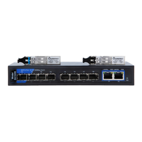
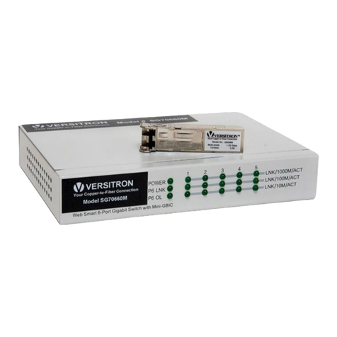
Versitron SG24816M User manual

SG24816M
24-Port Gigabit Switch
© May 2006
VERSITRON, Inc.
83Albe Drive – Suite C
Newark, DE 19702
www.versitron.com


SG24816M
8-Port TP + 16-Port SFP Fiber
L2 Managed Gigabit Switch User's Manual

Table of Contents
CAUTION-------------------------------------------------------------------------------------- V
ELECTRONIC EMISSION NOTICES--------------------------------------------------------- V
CHAPTER 1. INTRODUCTION--------------------------------------------------------- 2
1-1. OVERVIEW OF THE SG24816M SWITCH-------------------------------------------- 2
1-2. CHECKLIST ----------------------------------------------------------------------------- 4
1-3. FEATURES ------------------------------------------------------------------------------ 4
1-4. VIEW OF THE SG24816M SWITCH -------------------------------------------------- 6
1-4-1. User Interfaces on the Front Panel (Button, LEDs and Plugs)----- 6
1-4-2. User Interfaces on the Rear Panel---------------------------------------- 7
1-5. VIEW OF THE OPTIONAL MODULES ------------------------------------------------- 8
CHAPTER 2. INSTALLATION ---------------------------------------------------------- 9
2-1. STARTING THE SG24816M SWITCH ------------------------------------------------ 9
2-1-1. Hardware and Cable Installation------------------------------------------- 9
2-1-2. Installing Chassis to a 19-Inch Wiring Closet Rail--------------------11
2-1-3. Cabling Requirements-------------------------------------------------------11
2-1-3-1. Cabling Requirements for TP Ports --------------------------------12
2-1-3-2. Cabling Requirements for 1000SX/LX SFP Module------------12
2-1-3-3. Switch Cascading in Topology---------------------------------------13
2-1-4. Configuring the Management Agent of the SG24816M Switch ---16
2-1-4-1. Configuring the Management Agent of the SG24816M Switch
through the Serial RS-232 Port-------------------------------------------------17
2-1-4-2. Configuring the Management Agent of the SG24816M Switch
through the Ethernet Port --------------------------------------------------------19
2-1-5. IPAddress Assignment------------------------------------------------------20
2-2.TYPICALAPPLICATIONS--------------------------------------------------------------25
CHAPTER 3. OPERATION OF WEB-BASED MANAGEMENT --------------26
3-1. WEB MANAGEMENT HOME OVERVIEW--------------------------------------------28
3-1-1. System Information-----------------------------------------------------------31
3-1-2. IP Configuration---------------------------------------------------------------33
3-1-3. Time Configuration -----------------------------------------------------------36
3-1-4. Account Configuration-------------------------------------------------------39
3-1-5. Management Policy----------------------------------------------------------40
3-1-6. Virtual Stack--------------------------------------------------------------------43
3-2. PORT CONFIGURATION --------------------------------------------------------------45
3-2-1.Port Status ----------------------------------------------------------------------45
3-2-2. Port Configuration ------------------------------------------------------------50

3-2-3. Simple Counter----------------------------------------------------------------52
3-2-4. Detail Counter -----------------------------------------------------------------54
3-3. MIRROR--------------------------------------------------------------------------------57
3-4. BANDWIDTH MANAGEMENT ---------------------------------------------------------58
3-5. QOS(QUALITY OF SERVICE)CONFIGURATION -----------------------------------60
3-6. SNMPCONFIGURATION-------------------------------------------------------------70
3-7. IGMPSNOOPING---------------------------------------------------------------------72
3-8. MAX.PACKET LENGTH---------------------------------------------------------------76
3-9. DHCPBOOT--------------------------------------------------------------------------77
3-10. VLAN---------------------------------------------------------------------------------78
3-10-1. VLAN Mode ------------------------------------------------------------------78
3-10-2. Tag-based Group------------------------------------------------------------81
3-10-3. Port-based Group-----------------------------------------------------------83
3-10-4. Tag Rule-----------------------------------------------------------------------85
3-11. MACTABLE--------------------------------------------------------------------------87
3-12. GVRPCONFIGURATION -----------------------------------------------------------94
3-13. STPCONFIGURATION------------------------------------------------------------100
3-13-1. STP Status------------------------------------------------------------------100
3-13-2. STP Configuration --------------------------------------------------------102
3-13-3. STP Port Configuration--------------------------------------------------104
3-14.TRUNKING CONFIGURATION-----------------------------------------------------107
3-15. 802.1X CONFIGURATION -------------------------------------------------------- 114
3-16.ALARM CONFIGURATION ---------------------------------------------------------124
3-17. CONFIGURATION ------------------------------------------------------------------127
3-17-1. Save/Restore --------------------------------------------------------------128
3-17-2. Config File ------------------------------------------------------------------131
3-18. DIAGNOSTICS----------------------------------------------------------------------132
3-19.TFTPSERVER --------------------------------------------------------------------135
3-20. LOG ---------------------------------------------------------------------------------136
3-21. FIRMWARE UPGRADE ------------------------------------------------------------138
3-22. REBOOT----------------------------------------------------------------------------139
3-23. LOGOUT ----------------------------------------------------------------------------140
CHAPTER 4. OPERATION OF CLI MANAGEMENT--------------------------141
4-1. CLI MANAGEMENT -----------------------------------------------------------------141
4-1-1. Login---------------------------------------------------------------------------141
4-2. COMMANDS OF CLI ----------------------------------------------------------------143
4-2-1. Global Commands of CLI-------------------------------------------------144
4-2-2. Local Commands of CLI --------------------------------------------------149
CHAPTER 5. MAINTENANCE------------------------------------------------------- 227
5-1. RESOLVING NO LINK CONDITION-------------------------------------------------227
5-2. Q&A----------------------------------------------------------------------------------227
APPENDIX A TECHNICAL SPECIFICATIONS ----------------------------------228
APPENDIX B NULL MODEM CABLE SPECIFICATIONS--------------------232

PROPRIETARY DATA
All data in this manual is proprietary and may not be disclosed,
used or duplicated, for procurement or manufacturing purposes,
without prior written permission by VERSITRON, Inc.
WARRANTY
All VERSITRON products purchased after January 2001 carry a limited lifetime warranty
against defects in materials and workmanship for the lifetime of the product. Purchases
made prior to January 2001 are warranted for a period of one year from date of delivery.
VERSITRON reserves the right to repair or, at our option, replace parts which during normal
usage prove to be defective during the warranty period provided that:
1. You call VERSITRON at (302) 894-0699 or (800) 537-2296 and obtain a (RMA) Return
Authorization Number. Please reference your RMA number on the outside of the box in
which the item is returned.
2. Shipping charges are pre-paid.
No other warranty is expressed or implied and we are not liable for consequential damages.
For repairs outside of the warranty period, the same procedure must be followed.

Caution
Circuit devices are sensitive to static electricity, which can damage their delicate
electronics. Dry weather conditions or walking across a carpeted floor may cause you to
acquire a static electrical charge.
To protect your device, always:
•Touch the metal chassis of your computer to ground the static electrical charge before
you pick up the circuit device.
•Pick up the device by holding it on the left and right edges only.
Electronic Emission Notices
Federal Communications Commission (FCC) Statement
This equipment has been tested and found to comply with the limits for a class A
computing device pursuant to Subpart J of part 15 of FCC Rules, which are designed to
provide reasonable protection against such interference when operated in a commercial
environment.
European Community (CE) Electromagnetic Compatibility Directive
This equipment has been tested and found to comply with the protection requirements
of European Emission Standard EN55022/EN60555-2 and the Generic European Immunity
Standard EN50082-1.
EMC:
EN55022(1988)/CISPR-22(1985) classA
EN60555-2(1995) classA
EN60555-3
IEC1000-4-2(1995) 4K V CD, 8KV, AD
IEC1000-4-3(1995) 3V/m
IEC1000-4-4(1995) 1KV – (power line), 0.5KV – (signal line)


About this user’s manual
In this user’s manual, it will not only tell you how to install and connect your
network system but configure and monitor the SG248168M Managed Gigabit
Switch through the built-in CLI and web by RS-232 serial interface and Ethernet
ports step-by-step. Many explanation in detail of hardware and software functions
are shown as well as the examples of the operation for web-based interface and
command-line interface (CLI).
Overview of this user’s manual
Chapter 1 “Introduction” describes the features of SG24816M
Chapter 2 “Installation”
Chapter 3 “Operation of Web-based Management”
Chapter 4 “Operation of CLI Management”
Chapter 5 “Maintenance”

User Manual 2
www.versitron.com SG24816M
1. Introduction
1-1. Overview of SG24816M
The SG24816M 24-port Gigabit L2 Managed Switch, is a standard switch
that meets all IEEE 802.3/u/x/z Gigabit, Fast Ethernet specifications. The switch
includes 8-Ports 10/100/1000Mbps TP and 16-Ports Gigabit SFP Fiber. The switch
can be managed through the RS-232 serial port via direct connection, or through an
Ethernet port using CLI or Web-based management unit, associated with SNMP
agent. With the SNMP agent, the network administrator can log into the switch to
monitor, configure and control each port’s activity. The overall network management
is enhanced and the network efficiency is also improved to accommodate high
bandwidth applications. In addition, the switch features comprehensive and useful
function such as QoS (Quality of Service), Spanning Tree, VLAN, Port Trunking,
Bandwidth Control, Port Security, SNMP/RMON, IGMP Snooping capability via the
intelligent software. It is suitable for both metro-LAN and office application.
In this switch, 1000Mbps SFP Fiber transceiver is used for high-speed
connection expansion.
10/100/1000Mbps TP is a standard Ethernet port that meets all IEEE
802.3/u/x/z Gigabit, Fast Ethernet specifications. 1000Mbps SFP Fiber transceiver
is a Gigabit Ethernet port that fully complies with all IEEE 802.3z and 1000Base-
SX/LX standards.
For upgrading firmware, please refer to the Section 3-21 or Section 4-2-2 for
more details. The switch will not stop operating while upgrading firmware and after
that, the configuration keeps unchanged.

User Manual 3
www.versitron.com SG24816M
• Key Features in the Device
QoS: Support Quality of Service by the IEEE 802.1P standard. There are two
priority queue and packet transmission schedule.
Spanning Tree:
Support IEEE 802.1D, IEEE 802.1w (RSTP: Rapid Spanning Tree
Protocol) standards.
VLAN:
Support Port-based VLAN and IEEE802.1Q Tag VLAN. Support 256 active
VLANs and VLAN ID 1~4094.
Port Trunking:
Support static port trunking and port trunking with IEEE 802.3ad LACP.
Bandwidth Control:
Support ingress and egress per port bandwidth control.
Port Security:
Support allowed, denied forwarding and port security with MAC address.
SNMP/RMON:
SNMP agent and RMON MIB. In the device, SNMP agent is a client
software which is operating over SNMP protocol used to receive the
command from SNMP manager (server site) and echo the corresponded
data, i.e. MIB object. Besides, SNMP agent will actively issue TRAP
information when happened.
RMON is the abbreviation of Remote Network Monitoring and is a branch of
the SNMP MIB.
The device supports MIB-2 (RFC 1213), Bridge MIB (RFC 1493), RMON
MIB (RFC 1757)-statistics Group 1,2,3,9, VLAN MIB (802.1Q, RFC2674),
Ethernet MIB (RFC 1643) and so on.
IGMP Snooping:
Support IGMP version 2 (RFC 2236): The function IGMP snooping is used
to establish the multicast groups to forward the multicast packet to the
member ports, and, in nature, avoid wasting the bandwidth while IP
multicast packets are running over the network.

User Manual 4
www.versitron.com SG24816M
1-2. Checklist
Before you start installing the switch, verify that the package contains the
following:
⎯SG24816M Gigabit Switch
⎯SFP Modules (optional)
⎯Mounting Accessory (for 19” Rack Shelf)
⎯This User's Manual on CD-ROM
⎯AC Power Cord
⎯RS-232 Cable
Please notify your sales representative immediately if any of the aforementioned
items is missing or damaged.
1-3. Features
The SG24816M, a standalone off-the-shelf switch, provides the
comprehensive features listed below for users to perform system network
administration and efficiently and securely serve your network.
• Hardware
• 8 10/100/1000MbpsAuto-negotiation Gigabit Ethernet TP ports
• 16 1000Mbps SFP fiber ports
• 400KB on-chip frame buffer
• Jumbo frame support
• Programmable classifier for QoS (Layer 4/Multimedia)
• 8K MAC address and 4K VLAN support (IEEE802.1Q)
• Per-port shaping, policing, and Broadcast Storm Control
• IEEE802.1Q-in-Q nested VLAN support
• Full-duplex flow control (IEEE802.3x) and half-duplex backpressure
• Extensive front-panel diagnostic LEDs; System: Power, TP Port1-8: LINK/ACT,
SPEED, SFP Port 9-24: SFP(LINK/ACT)
• Management
•Supports concisely the status of port and easily port configuration
•Supports per port traffic monitoring counters
• Supports a snapshot of the system Information when you login
• Supports port mirror function
• Supports the static trunk function

User Manual 5
www.versitron.com SG24816M
• Supports 802.1Q VLAN
• Supports user management and limits three users to login
• Maximal packet length can be up to 9216 bytes for jumbo frame application
• Supports DHCP Broadcasting Suppression to avoid network suspended or
crashed
• Supports to send the trap event while monitored events happened
•Supports default configuration which can be restored to overwrite the current
configuration which is working on via web browser and CLI
• Supports on-line plug/unplug SFP modules
• Supports Quality of Service (QoS) for real time applications based on the
information taken from Layer 2 to Layer 4, such as VoIP
• Built-in web-based management and CLI management, providing a more
convenient UI for the user
• Supports port mirror function with ingress traffic
•Supports rapid spanning tree (802.1w RSTP)
• Supports 802.1X port security on a VLAN
• Supports user management and only first login administrator can configure the
device. The rest of users can only view the switch
• SNMP access can be disabled and prevent from illegal SNMP access
• Supports Ingress, Non-unicast and Egress Bandwidth rating management with a
resolution of 1Mbps
• The trap event and alarm message can be transferred via e-mail and mobile
phone short message
• Supports diagnostics to let administrator knowing the hardware status
•Supports external loopback test to check if the link is ok
• TFTP for firmware upgrade, system log upload and config file import/export
• Supports remote boot the device through user interface and SNMP
• Supports network time synchronization and daylight saving
• Supports 120 event log records in the main memory and display on the local
console

User Manual 6
www.versitron.com SG24816M
1-4. View of SG24816M Gigabit Switch
1-4-1. User Interfaces on the Front Panel (Button, LEDs and Plugs)
There are 8 TP Gigabit Ethernet ports and 16 SFP fiber ports for optional
removable modules on the front panel of the switch. LED display area, locating on
the left side of the panel, contains a Power LED, which indicates the power status
and 24 ports working status of the switch.
Fig. 1-1 Full View of SG24816M
Fig. 1-2 Front View of SG24816M
RESET Button:
RESET button is used to
reset the management
system.
Power Indication LED
Gigabit Ethernet Port
TP Port Status Indication LEDs SFP Fiber Port
Fiber Port Status Indication LEDs

User Manual 7
www.versitron.com SG24816M
• LED Indicators
LED Color Function
System LED
POWER Green Lit when +5V DC power is on and good
CPU LED Green Blinks when CPU is activity
10/100/1000Ethernet TP Port 1 to 8 LED
LINK/ACT Green Lit when connection with remote device is good
Blinks when any traffic is present
Off when cable connection is not good
SPEED Green/
Ember
Lit green when 1000Mbps speed is active
Lit ember when 100Mbps speed is active
Off when 10Mbps speed is active
1000SX/LX Gigabit Fiber Port 9 to 24 LED
SFP(LINK/ACT) Green Lit when connection with the remote device is good
Blinks when any traffic is present
Off when module connection is not good
Table1-1
1-4-2. User Interfaces on the Rear Panel
One RS-232 DB-9 interface is offered for configuration or management.
Fig. 1-3 Rear View of SG24816M
RS-232 DB-9 Connector
AC Line 100-240V 50/60 Hz

User Manual 8
www.versitron.com SG24816M
1-5. View of the Optional Modules
In the switch, 1000Mbps SFP Fiber transceivers are used for high-speed
connection expansion; the following are optional SFP types provided for the switch:
⎯1000Mbps LC, MM, SFP Fiber transceiver
⎯1000Mbps LC, SM 10km, SFP Fiber transceiver
⎯1000Mbps LC, SM 30km, SFP Fiber transceiver
⎯1000Mbps LC, SM 50km, SFP Fiber transceiver
⎯1000Mbps BiDi LC, type 1, SM 20km, SFP Fiber WDM transceiver
⎯1000Mbps BiDi LC, type 2, SM 20km, SFP Fiber WDM transceiver
⎯1000Mbps LC, SM 10km, SFP Fiber transceiver with DDM
Fig. 1-4 Front View of 1000Base-SX/LX LC, SFP Fiber Transceiver
Fig. 1-5 Front View of 1000Base-LX BiDi LC, SFP Fiber Transceiver

User Manual 9
www.versitron.com SG24816M
2. Installation
2-1. Installing the SG24816M
This section will give users a quick start for:
- Hardware and Cable Installation
- Management Station Installation
- Software booting and configuration
2-1-1. Hardware and Cable Installation
At the beginning, please do first:
⇒Wear a grounding device to avoid the damage from electrostatic discharge
⇒Be sure that power switch is OFF before you insert the power cord to power
source
• Installing Optional SFP Fiber Transceivers to the Switch
Note: If you have no modules, please skip this section.
•Connecting the SFP Module to the Chassis:
The optional SFP modules are hot swappable, so you can plug or unplug it
before or after powering on.
1. Verify that the SFP module is the right model and conforms to the chassis
2. Slide the module along the slot. Also be sure that the module is properly
seated against the slot socket/connector
3. Install the media cable for network connection
4. Repeat the above steps, as needed, for each module to be installed into
slot(s)
5. Have the power ON after the above procedures are done
Fi
g
. 2-1 Installation of O
p
tional SFP Fiber Transceive
r

User Manual 10
www.versitron.com SG24816M
• TP Port and Cable Installation
⇒In the switch, TP port supports MDI/MDI-X auto-crossover, so both types of
cable, straight-through (Cable pin-outs for RJ-45 jack 1, 2, 3, 6 to 1, 2, 3, 6 in
10/100M TP; 1, 2, 3, 4, 5, 6, 7, 8 to 1, 2, 3, 4, 5, 6, 7, 8 in Gigabit TP) and
crossed-over (Cable pin-outs for RJ-45 jack 1, 2, 3, 6 to 3, 6, 1, 2) can be used.
It means you do not have to tell from them, just plug it.
⇒Use Cat. 5 grade RJ-45 TP cable to connect to a TP port of the switch and the
other end is connected to a network-aware device such as a workstation or a
server.
⇒Repeat the above steps, as needed, for each RJ-45 port to be connected to a
Gigabit 10/100/1000 TP device.
Now, you can start having the switch in operation.
• Power On
The switch supports 100-240 VAC, 50-60 Hz power supply. The power
supply will automatically convert the local AC power source to DC power. It does not
matter whether any connection plugged into the switch or not when power on, even
modules as well. After the power is on, all LED indicators will light up immediately
and then all off except the power LED still keeps on. This represents a reset of the
system.
• Firmware Loading
After resetting, the bootloader will load the firmware into the memory. It will
take about 30 seconds, after that, the switch will flash all the LED once and
automatically performs self-test and is in ready state.

User Manual 11
www.versitron.com SG24816M
2-1-2. Installing the switch into a 19-Inch Wiring Closet Rail
Caution: Allow a proper spacing and proper air ventilation for the cooling fan
at both sides of the chassis.
⇒Wear a grounding device for electrostatic discharge.
⇒Screw the mounting accessory to the front side of the switch (See Fig. 2-2).
⇒Place the Chassis into the 19-inch wiring closet rail and locate it at the proper
position. Then, fix the Chassis by screwing it.
2-1-3. Cabling Requirements
To help ensure a successful installation and keep the network performance
good, please take a care on the cabling requirement. Cables with worse
specification will render the LAN to work poorly.
Fig. 2-2

User Manual 12
www.versitron.com SG24816M
2-1-3-1. Cabling Requirements for TP Ports
⇒For Fast Ethernet TP network connection
⎯The grade of the cable must be Cat. 5 or Cat. 5e with a maximum length of
100 meters.
⇒Gigabit Ethernet TP network connection
⎯The grade of the cable must be Cat. 5 or Cat. 5e with a maximum length of
100 meters. Cat. 5e is recommended.
2-1-3-2. Cabling Requirements for 1000SX/LX SFP Module
It is more complex and comprehensive contrast to TP cabling in the fiber
media. Basically, there are two categories of fiber, multi mode (MM) and single
mode (SM). The later is categorized into several classes by the distance it supports.
They are SX, LX, LHX, XD, and ZX. From the viewpoint of connector type, there
mainly are LC and BIDI LC.
⎯Gigabit Fiber with multi-mode LC SFP module
⎯Gigabit Fiber with single-mode LC SFP module
⎯Gigabit Fiber with BiDi LC 1310nm SFP module
⎯Gigabit Fiber with BiDi LC 1550nm SFP module
The following table lists the types of fiber that we support and those else not
listed here are available upon request.
Multi-mode Fiber Cable and Modal Bandwidth
Multi-mode 62.5/125μm Multi-mode 50/125μm
Modal
Bandwidth Distance Modal
Bandwidth Distance
160MHz-Km 220m 400MHz-Km 500m
IEEE 802.3z
Gigabit Ethernet
1000SX 850nm
200MHz-Km 275m 500MHz-Km 550m
Single-mode Fiber 9/125μm
Single-mode transceiver 1310nm 10Km
1000Base-
LX/LHX/XD/ZX Single-mode transceiver 1550nm 30, 50Km
TX(Transmit) 1310nm
Single-Mode
*20Km RX(Receive) 1550nm
TX(Transmit) 1550nm
1000Base-LX
Single Fiber
(BIDI LC) Single-Mode
*20Km RX(Receive) 1310nm
Table2-1
Table of contents
Other Versitron Switch manuals

Versitron
Versitron SG10208 User manual

Versitron
Versitron SGX368244M User manual

Versitron
Versitron S71650 User manual

Versitron
Versitron SG70660M User manual

Versitron
Versitron SG71090 User manual

Versitron
Versitron SG70660M User manual

Versitron
Versitron Web Smart+ SG71070M User manual

Versitron
Versitron SG09108 User manual

Versitron
Versitron S72450 User manual

Versitron
Versitron SF71060M User manual
Popular Switch manuals by other brands

Cisco
Cisco Catalyst 3750E-48PD-F Getting started guide

Greengate
Greengate VNW-P-1001-DMV-W Installation instructions and owner's manual

Atlona
Atlona JunoX 451 HDBT manual

Belden
Belden Hirschmann SPIDER 8TX EEC Installation

Metel
Metel 200M-2.0.4.ECA installation manual

Lenovo
Lenovo SI4091 installation guide