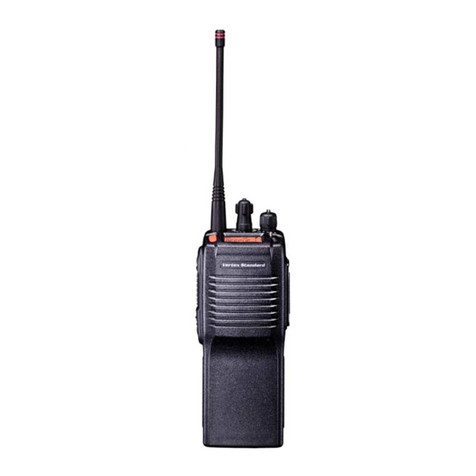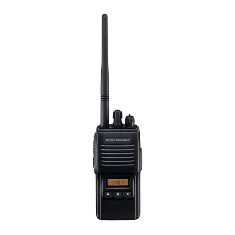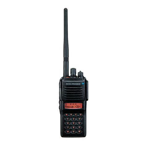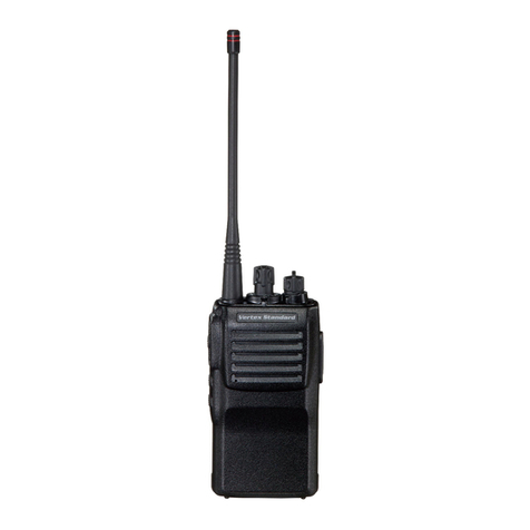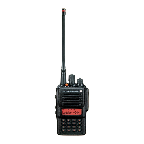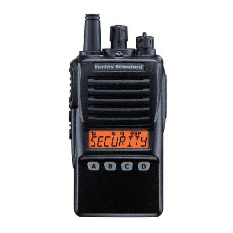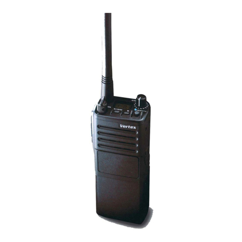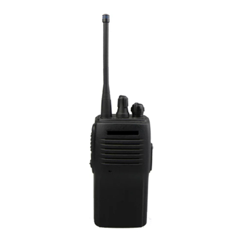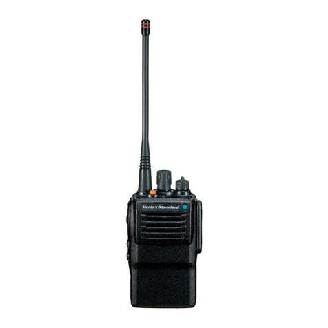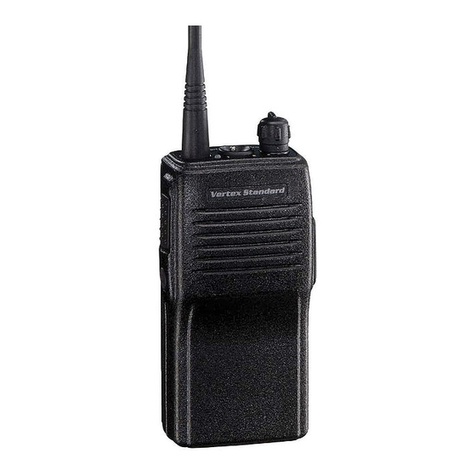
controlS & connectorS
Before you Begin
Battery paCk inStallatiOn anD reMOVal
Toinstall thebattery,hold thetrans-
ceiverwith yourlefthand,soyour
palmisoverthespeakerand
yourthumbisonthe
topofthebeltclip.In-
sert the battery pack
intothebattery
compartment on
the back of the
radiowhiletilting
theBeltClipoutward,thenpushthebottomsideofthebat-
terypackuntilthebatterypacklockswiththeBatteryPack
Latch.
To remove the battery, turn the radio off and remove any
protectivecases.Slide the Battery PackLatchonthe bot-
tomof theradio, thenslidethebatterydownwardandout
fromtheradiowhileholdingtheBeltClip.
Battery CharGe
1. InserttheDCplugfromtheoptionalPA-
42AC Adapter into the DC jack on the
bottomsideoftheoptionalCD-34Desk-
top Rapid Charger, then plug the PA-42
ACAdapterintotheAClineoutlet.
2. Turn thetransceiver“off”,theninsert
the transceiver into the CD-34Desktop
RapidChargerwhilealigningtheslots
ofthebatterypackwiththeguides in
thenestoftheCD-34;refertotheil-
lustration below for details on proper
positioningofthebatterypack.
3.Ifthetransceiverisinsertedcorrectly,
theLEDindicatorwill glow
red.Afully-dischargedpack
will be charged completely in
approximately2.5hours.
4. TheLEDindicatorwillchangetogreenwhencharging
isnearingcompletion.Thebatterypackbecomesfully
chargedapproximately30minuteslater.
5. Whenchargingis completed,remove thetransceiverfrom
theCD-34DesktopRapidCharger,andunplugthePA-42
ACAdapterfromtheAClineoutlet.
Important Notes!
DonotconnectanimproperACAdaptertotheCD-34
DesktopRapidCharger.Use only theoptional PA-42AC
Adapter.
DisconnectthetransceiverfromtheCD-34DesktopRapid
Charger, and unplug the PA-42ACAdapter from theAC
lineoutlet,whenchargingiscompleted.
The PA-42ACAdapterand/orCD-34DesktopRapid
Chargerwillgenerateamoderateamountofheatduringthe
chargingprocess.Thisisanormalcondition.
ThePA-42ACAdapterandCD-34DesktopRapid Char-
ger is designed for charging only, and is not designed for
operation(transmission/reception)ofthetransceiver.
Periodicallywipe thechargingterminalsinthenestofthe
CD-34DesktopRapidCharger,usingadrycloth,toensure
goodconnectionsbetweenthechargerandbattery.
Caution!!
Whencharging abattery packalone(not attachedto the
transceiver),donotallowanymetalobjecttoshorttheter-
minalsonthebatterypack.
Donot allowanymetal objectstoshort theterminals in
thenestoftheCD-34 DesktopRapidCharger,asashort-
circuitcouldcauseoverheatingofthechargercircuitry.
cAution!
Do not attempt to open any of the rechargeable Lith-
ium-Ion packs, as they could explode if accidentally
short-circuited.
operAtion
OperatiOn quiCk Start
Turn the top panel’s VOL/PWR knob
clockwisetoturnontheradio.
Turnthetoppanel’sCHselectorknob
to choose the desired operating chan-
nel.
Rotate theVOL/PWR knob to set the
volume level. If no signal is present,
press and hold in the [SIDE 1] key
(default:[MONI/SQL OFF] key) for
morethanonesecond;background
noise will now be heard, and you may use this to set the
VOL/PWRknobforthedesiredaudiolevel.
Pressandhold inthe[SIDE 1] key
(default:[MONI/SQL OFF] key) for
morethanonesecond(orpressthekey
twice)toquietthenoiseandresume
normal(quiet)monitoring.
Totransmit,monitorthechannelandmakesureitisclear.
Totransmit,pressandholdinthePTT
switch.Speakintothemicrophonearea
ofthe frontpanelgrille(lowerright-
hand corner) in a normal voice level.
ToreturntotheReceivemode,release
thePTTswitch.
Pressthe[SIDE 2] key(default:[SCAN]key)tostart
scanning.Ifandwhenthescanner
encountersasignalstrongenough
toopenthesquelch,the scannerwill
remain halted for as long as there is
carrierpresentonthechannel.Afterthe
carrierdropsattheendoftheotherstation’stransmission,
scanningwillresume.
IfaSpeaker/Microphone isavailable,remove the plastic
cap and its two mounting screws from the right side of
thetransceiver,theninserttheplugfromthe Speaker/
Microphone into the MIC/SP jack; secure the plug using
thescrews suppliedwiththeSpeaker/Microphone.Hold
the speaker grille up next to your ear while receiving. To
transmit,pressthePTTswitchontheSpeaker/Microphone,
justasyouwouldonthemaintransceiver’sbody.
Note : Save the original plastic cap and its mounting
screws. They should be re-installed when not using the
Speaker/Microphone.
lOw Battery inDiCatiOn
As the battery discharges during use, the voltage gradually
becomeslower.Whenthebatteryvoltagebecomestolow,
substituteafreshlychargedbatteryandrechargethedepleted
pack.Whenthebatteryvoltagebecomestolow,theLEDindi-
catoronthetopoftheradiowillblinkredandanalertbeeper
willsound.
progrAMMABle key functionS
TheVX-241PMR446provide[SIDE 1]and[SIDE 2]keys.
These“Programmable”keysfunctionscanbecustomized(set
tootherfunctions)viatheCE141ProgrammingSoftware.
ThepossibleProgrammablekeyfeaturesareillustratedbelow,
and their functions are explained below. For further details,
contactyourVertexStandarddealer.
Forfuturereference,checktheboxatthebelowtoeachfunc-
tionthathasbeenassignedtotheProgrammablekeyonyour
particularradio,andkeepithandy.
FunCtiOn
prOGraMMaBle key
(preSS / preSS anD hOlD)
[SiDe1] key [SiDe2] key
Monitor / /
SQL Off / /
Scan / /
Follow-Me Scan / /
prOGraMMaBle key DeFault SettinG
[SiDe1] key [SiDe2] key
preSS key Monitor Scan
preSS & hOlD key SQL Off ---
operAting MAnuAl
MOnitOr
Press (or Press and hold) the assigned Programmable key
todisabletheCTCSS-andDCS-controlledsquelch;theLED
indicatoronthetopofthetransceiverwillglowgreen.
Sql OFF
Press (or Press and hold) the assigned Programmable key
to hear background noise (unmute the transceiver); the LED
indicatoronthetopofthetransceiverwillblinkgreen.
SCan
TheScanningfeatureisused tomonitormultiplechannels
programmed into the transceiver. While scanning, the trans-
ceiver will check each channel for the presence of asignal,
andwillstoponachannelifasignalispresent.
To activate scanning:
Press (or Press and hold) the assigned Programmable
key.
Thescanner willsearch thechannels, lookingforactive
ones; it will pause each time it nds a channel on which
someoneisspeaking.
To stop scanning:
Press (or Press and hold) the assigned Programmable
keyagain.
FOllOw-Me SCan
The“Follow-Me”ScanfeaturechecksaUser-assignedPrior-
ityChannelregularlyasyouscanotherchannels.Thus,ifonly
Channels1,3,and5(ofthe8availablechannels)aredesignat-
edfor“Scanning,”theusermaynonethelessassignChannel2
asthe“User-assigned”PriorityChannelviathe“Follow-Me”
feature.
Toactivate“Follow-Me”scanning,rstselectthechannelyou
wantto designateasthe“User-AssignedPriority Channel”
and press (or press and hold) the assigned Programmable
key.Whenthescannerstopsonan“Active”channel,theUser-
assignedPriorityChannelwillautomaticallybecheckedevery
few seconds; if activity is found on the User-assigned Prior-
ityChannel, theradiowill switchbetween itandtheDealer-
AssignedPriorityChannel,ifany.
AdVAnced feAture
Youmaysetthefollowingfeaturesineachoperatingchannel
viatheCE141ProgrammingSoftwareindependently.
Dial SCan
When set the CH selector knob to the channel which a Dial
Scanfeaturewasassigned,thescannerbeginsautomatically.
priOrity CheCk
ThePriority CheckfeaturechecksaUser-assignedPriority
Channeleveryveseconds,whenthescannerstoppedonthe
channelexcepttheUser-assignedPriorityChannel.
tiMe-Out tiMer (tOt)
TheTOTfeatureprovidesasafetyswitch,whichlimitstrans-
mission time to a pre-programmed value. This will conserve
battery power by limiting the length of transmissions. When
yourtransmission timeis within10 secondsof theTime-Out
Timerexpiration,analertbellwillprovideanaudiblewarning
fromthespeaker.
BuSy Channel lOCk-Out (BClO)
TheBCLOfeaturepreventstheradio’stransmitterfrombeing
activatedifasignalstrongenoughtobreakthroughthe“noise”
squelchispresent.
artS (autO ranGe tranSpOnD SySteM)
Thissystemisdesignedtoinformyouwhenyouandanother
ARTS-equippedstationarewithincommunicationrange.
DuringARTSoperation,yourradioautomaticallytransmits
for about 1 second every 55 seconds in an attempt to shake
handswiththeotherstation.
If you are out of range for more than 2 minutes, your radio
sensesthatnosignalhasbeenreceived,threeshortbeeperwill
sound.Ifyousubsequentlymove backintorange,assoonas
theotherstationtransmits,ashortbeeperwillsound.
pOwer SaVe
ThePowerSavefeatureputsthetransceivertosleepfora
time interval, periodically “waking it up” to check for activ-
ity.Ifsomebodyistalkingonthechannel,thetransceiverwill
remain in the “active” mode, then resume its “sleep” cycles
whenthesignaldrops.Thisfeaturesignicantlyreduces qui-
escentchannelbatterydrain.
progrAMMABle key functionS
Align the slots of the battery
pack with the guides in the
nest of the CD-34 Desktop
Rapid Charger.
Push To Talk
(PTT) Switch
[SIDE1] Key
[SIDE2] Key
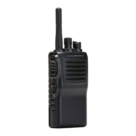
Antenna
Speaker
CH (Channel) Selector
VOL/PWR Knob
Microphone
MIC/SP Jack
LED Indicator
Glows Green: SCAN or Follow Me SCAN is activated (or Monitor on)
Blinking Green: Busy Channel (or SQL off)
Glows Red: Transmitting
Blinking Red: Battery Voltage is Low
Battery Pack Latch
Tilt the Belt Clip
Insert the Battery Pack
Push the bottom side
of the Battery Pack
Copyright2014
VertexStandardLMR,Inc.
Allrightsreserved.
Noportionofthismanual
maybereproduced
withoutthepermissionof
VertexStandardLMR,Inc.
