Vertical Express HD98 User manual

HD98 Door Operator
with Owner’s Service Tool (OST)

Every attempt has been made to ensure that this documentation is as accurate and up-to-date as possible.
However, Vertical Express assumes no liability for consequences, directly or indirectly, resulting from any error or
omission. The material contained herein is subject to revision. Please report any problems with this manual to
Vertical Express, P.O. Box 2019, Memphis, Tennessee 38101.
Vertical Express • P.O. Box 2019 • Memphis, Tennessee 38101
© 2005, 2011 Vertical Express. All rights reserved.
Published February, 2005
Third Edition, November 2011
Printed in the United States of America
Manual Number: 89170 v.1.1

HD-98 Door Operator with OST Contents
Printed in USA November, 2011 1
Contents
Safety Precautions . . . . . . . . . . . . . . . . . . . . . . . . . . . . . . . . . . . . . . . . . . . . . . . . . . . . . . . . . . . . . . . . 3
General Safety . . . . . . . . . . . . . . . . . . . . . . . . . . . . . . . . . . . . . . . . . . . . . . . . . . . . . . . . . . . . . 3
Electrical Safety . . . . . . . . . . . . . . . . . . . . . . . . . . . . . . . . . . . . . . . . . . . . . . . . . . . . . . . . . . . . 3
Mechanical Safety . . . . . . . . . . . . . . . . . . . . . . . . . . . . . . . . . . . . . . . . . . . . . . . . . . . . . . . . . . 4
Arrival of Equipment . . . . . . . . . . . . . . . . . . . . . . . . . . . . . . . . . . . . . . . . . . . . . . . . . . . . . . . . 5
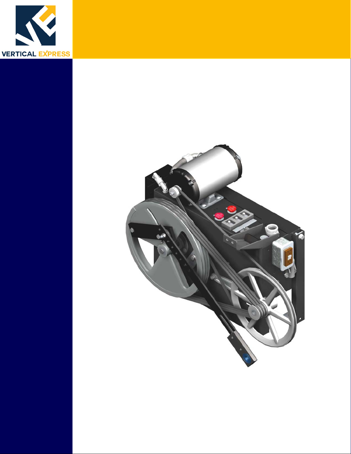
Overview . . . . . . . . . . . . . . . . . . . . . . . . . . . . . . . . . . . . . . . . . . . . . . . . . . . . . . . . . . . . . . . . . . . . . . . 7
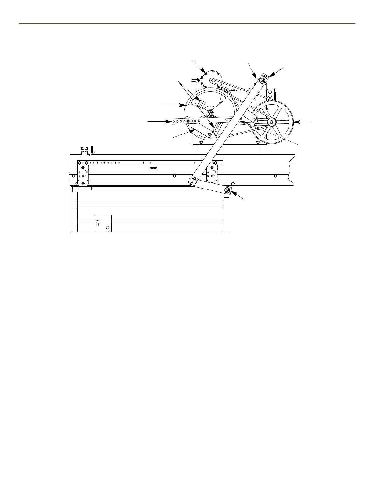
Mechanical Installation and Adjustment . . . . . . . . . . . . . . . . . . . . . . . . . . . . . . . . . . . . . . . . . . . . . . . . . 8
Preparing the Door Operator . . . . . . . . . . . . . . . . . . . . . . . . . . . . . . . . . . . . . . . . . . . . . . . . . . . 8
Mounting the Door Operator . . . . . . . . . . . . . . . . . . . . . . . . . . . . . . . . . . . . . . . . . . . . . . . . . . . 9
Setting the Stroke. . . . . . . . . . . . . . . . . . . . . . . . . . . . . . . . . . . . . . . . . . . . . . . . . . . . . . . . . . 11
Adjusting the Drive Arms . . . . . . . . . . . . . . . . . . . . . . . . . . . . . . . . . . . . . . . . . . . . . . . . . . . . 12
Setting the Mechanical Stops . . . . . . . . . . . . . . . . . . . . . . . . . . . . . . . . . . . . . . . . . . . . . . . . . 14
Adjustment . . . . . . . . . . . . . . . . . . . . . . . . . . . . . . . . . . . . . . . . . . . . . . . . . . . . . . . . . . . . . . . . . . . . . 14
Limit Setting and Direction Check . . . . . . . . . . . . . . . . . . . . . . . . . . . . . . . . . . . . . . . . . . . . . . 14
Door Card Configuration . . . . . . . . . . . . . . . . . . . . . . . . . . . . . . . . . . . . . . . . . . . . . . . . . . . . . 15
Door Setup . . . . . . . . . . . . . . . . . . . . . . . . . . . . . . . . . . . . . . . . . . . . . . . . . . . . . . . . . . . . . . . . . . . . . 16
Nudging Duty . . . . . . . . . . . . . . . . . . . . . . . . . . . . . . . . . . . . . . . . . . . . . . . . . . . . . . . . . . . . . 17
Final Door Adjustments. . . . . . . . . . . . . . . . . . . . . . . . . . . . . . . . . . . . . . . . . . . . . . . . . . . . . . 18
Open Adjustments Procedure . . . . . . . . . . . . . . . . . . . . . . . . . . . . . . . . . . . . . . . . . . . . . . . . . 18
Close Adjustments Procedure . . . . . . . . . . . . . . . . . . . . . . . . . . . . . . . . . . . . . . . . . . . . . . . . . 19
Torque. . . . . . . . . . . . . . . . . . . . . . . . . . . . . . . . . . . . . . . . . . . . . . . . . . . . . . . . . . . . . . . . . . 20
Reopen Adjustment . . . . . . . . . . . . . . . . . . . . . . . . . . . . . . . . . . . . . . . . . . . . . . . . . . . . . . . . 20
High Speed Clamp Adjustment . . . . . . . . . . . . . . . . . . . . . . . . . . . . . . . . . . . . . . . . . . . . . . . . 20
Save Door Adjustments (WRT) . . . . . . . . . . . . . . . . . . . . . . . . . . . . . . . . . . . . . . . . . . . . . . . . 20
Door Adjustment Diagrams. . . . . . . . . . . . . . . . . . . . . . . . . . . . . . . . . . . . . . . . . . . . . . . . . . . 21
Setting the Gate Switch. . . . . . . . . . . . . . . . . . . . . . . . . . . . . . . . . . . . . . . . . . . . . . . . . . . . . . 22
Final Security . . . . . . . . . . . . . . . . . . . . . . . . . . . . . . . . . . . . . . . . . . . . . . . . . . . . . . . . . . . . . 22
Diagnostics . . . . . . . . . . . . . . . . . . . . . . . . . . . . . . . . . . . . . . . . . . . . . . . . . . . . . . . . . . . . . . . . . . . . . 23
Electronic Door Operator Adjustments. . . . . . . . . . . . . . . . . . . . . . . . . . . . . . . . . . . . . . . . . . . 23
Electronic Door Faults. . . . . . . . . . . . . . . . . . . . . . . . . . . . . . . . . . . . . . . . . . . . . . . . . . . . . . . 25

Contents HD-98 Door Operator with OST
2Vertical Express
Contents
(
continued
)
Troubleshooting . . . . . . . . . . . . . . . . . . . . . . . . . . . . . . . . . . . . . . . . . . . . . . . . . . . . . . . . . . . . . . . . . 28
Door Operator Parts . . . . . . . . . . . . . . . . . . . . . . . . . . . . . . . . . . . . . . . . . . . . . . . . . . . . . . . . 28
Mechanical Troubleshooting . . . . . . . . . . . . . . . . . . . . . . . . . . . . . . . . . . . . . . . . . . . . . . . . . . 28
Troubleshooting Guide . . . . . . . . . . . . . . . . . . . . . . . . . . . . . . . . . . . . . . . . . . . . . . . . . . . . . . 29
Power Supply Checks . . . . . . . . . . . . . . . . . . . . . . . . . . . . . . . . . . . . . . . . . . . . . . . . . . . . . . . 29
Phasing J2, Motor Leads, and Encoder Connections. . . . . . . . . . . . . . . . . . . . . . . . . . . . . . . . . 31
Phase A and Phase B Motor Sensor Check. . . . . . . . . . . . . . . . . . . . . . . . . . . . . . . . . . . . . . . . 32
DOL and DCL Check . . . . . . . . . . . . . . . . . . . . . . . . . . . . . . . . . . . . . . . . . . . . . . . . . . . . . . . . 32
Door Operator I/O Checks . . . . . . . . . . . . . . . . . . . . . . . . . . . . . . . . . . . . . . . . . . . . . . . . . . . . 32
SE, EE, DR, and WDP . . . . . . . . . . . . . . . . . . . . . . . . . . . . . . . . . . . . . . . . . . . . . . . . . . . . . . . 33
Door Communications Troubleshooting . . . . . . . . . . . . . . . . . . . . . . . . . . . . . . . . . . . . . . . . . . 34
Wiring Diagrams . . . . . . . . . . . . . . . . . . . . . . . . . . . . . . . . . . . . . . . . . . . . . . . . . . . . . . . . . . . . . . . . . 36
Maintenance . . . . . . . . . . . . . . . . . . . . . . . . . . . . . . . . . . . . . . . . . . . . . . . . . . . . . . . . . . . . . . . . . . . . 38
Replacement Parts . . . . . . . . . . . . . . . . . . . . . . . . . . . . . . . . . . . . . . . . . . . . . . . . . . . . . . . . . . . . . . . . 39

Safety Precautions HD-98 Door Operator with OST
3
Printed in USA November, 2011
Safety Precautions
IMPORTANT! Read this page before any work is performed on elevator equipment. The
procedures contained in this manual are intended for the use of qualified
elevator personnel. In the interest of your personal safety and the safety of
others, do not attempt any procedure that you are not qualified to perform.
All procedures must be accomplished in accordance with the applicable rules in the latest edition of
the National Electrical Code, the latest edition of ASME A17.1, and any governing local codes.
Terms in This Manual
CAUTION statements identify conditions that may result in damage to the
equipment or other property if improper procedures are followed.
WARNING statements identify conditions that may result in personal injury if
improper procedures are followed.
General Safety
Before applying power to the controller, check that all factory wire connections
are tight on relays, contactors, fuse blocks, resistors, and terminals on cards and
DIN rail terminals. Connections loosened during shipment may cause damage or
intermittent operation.
Other specific warnings and cautions are found where applicable and do not appear in this sum-
mary. See the
Elevator Industry Field Employees’ Safety Handbook
for electrical equipment
safety information on installation and service.
Electrical Safety All wiring must be in accordance with the National Electrical Code and be consistent with all state
and local codes.
Use the Proper Fuse
To avoid fire hazards, use only a fuse of the correct type, voltage, and current rating. See the job
specific drawings sheet (Power Supplies) for fusing information.
Electric shocks can cause personal injury or loss of life. Circuit breakers, switches, and fuses may
not disconnect all power to the equipment. Always refer to the wiring diagrams. Whether the AC
supply is grounded or not, high voltage will be present at many points.
Printed Circuit Cards
Printed circuit boards may be damaged if removed or installed in the circuit while applying power.
Before installation and/or removing printed circuit boards, secure all power.
Always store and ship printed circuit cards in separate static bags.

HD-98 Door Operator with OST Safety Precautions
4Vertical Express
(continued)
(continued)
Electrical Safety Mainline Disconnect
Unless otherwise directed, always Turn OFF, Lock, and Tag out the mainline disconnect to remove
power from elevator equipment. Before proceeding, confirm that the equipment is de-energized
with a volt meter. Refer to the
Elevator Industry Field Employees’ Safety and Accident Prevention
Program Manual
for the required procedure.
Test Equipment Safety
Always refer to manufacturers’ instruction book for proper test equipment operation and adjust-
ments.
Megger or buzzer-type continuity testers can damage electronic components. Connection of
devices such as voltmeters on certain low level analog circuits may degrade electronic system per-
formance. Always use a voltmeter with a minimum impedance of 1M Ohm/Volt. A digital voltmeter
is recommended.
When Power Is On
To avoid personal injury, do not touch exposed electrical connections or components while power is
ON.
Mechanical Safety See the
Elevator Industry Field Employees’ Safety Handbook
for mechanical equipment safety
information on installation and service.

Safety Precautions HD-98 Door Operator with OST
5
Printed in USA November, 2011
Static Protection Guidelines
IMPORTANT! Read this page before working with electronic circuit boards.
Elevator control systems use a number of electronic cards to control various functions of the
elevator. These cards have components that are extremely sensitive to static electricity and are
susceptible to damage by static discharge.
Immediate and long-term operation of an electronic-based system depends upon the proper
handling and shipping of its cards. For this reason, the factory bases warranty decisions on the
guidelines below.
Handling • Cards shipped from the factory in separate static bags must remain in the bags until time for
installation.
• Anti-static protection devices, such as wrist straps with ground wire, are required when
handling circuit boards.
• Cards must not be placed on any surface without adequate static protection.
• Only handle circuit cards by their edges, and only after discharging personal static electricity to
a grounding source. DO NOT touch the components or traces on the circuit card.
• Extra care must be taken when handling individual, discrete components such as EPROMS
(which do not have circuit card traces and components for suppression).
Shipping • Complete the included board discrepancy sheet.
• Any card returned to the factory must be packaged in a static bag designed for the card.
• Any card returned to the factory must be packaged in a shipping carton designed for the card.
• “Peanuts” and styrofoam are unacceptable packing materials.
Note: Refer to the
Vertical Express Replacement Parts Catalog
to order extra static bags and
shipping cartons for each card.
Failure to adhere to the above guidelines will VOID the card warranty!

HD-98 Door Operator with OST Contents
6Vertical Express
Contents
This page
intentionally
left blank.

HD-98 Door Operator with OST Overview
Printed in USA November, 2011 7
Overview
The following is a list of the major components of a door operator including a description of
their functions, an overview of some of the critical adjustments, and maintenance information.
See Figure 1 on page 8.
• Adjustable Arm - The arm mounted to the drive wheel is used to change the amount
of linear door movement or stroke.
• Connecting Arm - Connects the drive arm to the door panel.
• Door Operator Support - A metal plate welded to the header. The door operator is
mounted to the door operator support with four bolts through the four mounting slots of
the door operator.
• Drive Arm - The linkage connected between the drive arm support and the connecting
arm.
• Drive Arm Support - The bracket containing two holes is located on top of the door
operator. The drive arm should be connected to the right-hand hole, looking from the
hatch, at the front of the door operator.
• Drive Wheel - A metal sheave containing a slotted cam surface. The adjustable arm
mounts to the drive wheel and is adjusted in the slotted cam surface. The drive wheel is
driven by the jack shaft sheave using 3 V belts.
To change the linear door travel or stroke, move the adjustable arm:
• Closer to the center of the drive wheel = less door travel for the same amount of wheel
rotation.
• Further from the center of the drive wheel = more door travel for the same amount of
wheel rotation.
• Idler Arm - An adjustable arm mounted to the front of the door operator which controls the
tension of the 3 V belts between the jack shaft sheave and the drive wheel.
• Intermediate Arm - Adjustable linkage connected between the drive wheel adjustable arm
and the pivot arm. The connection at the pivot arm is adjustable to control the length of the
intermediate arm.
• Mechanical Stops - Metal L brackets mounted to the front of the door operator. The stops
have slots to adjust the amount of drive wheel rotation and, once positioned, they limit the
physical rotation of the drive wheel.
• Motor - 115V or 230V DC Motor
• Pivot Arm - Connects the drive arm to the intermediate arm and provides an adjustment
for the length of the intermediate arm.
• Sheave, Jack Shaft - A spoked sheave driven by the door operator motor with a single
V belt. The motor sheave drives the jack shaft sheave which drives the drive wheel.
• Sheave, Motor - A sheave attached directly to the door operator motor shaft.
• Support Strut - Unistrut legs on the rear of the door operator which are used to secure the
rear of the operator to the car top, and also to plumb the face of the drive wheel.

Mechanical Installation and Adjustment HD-98 Door Operator with OST
8Vertical Express
Overview
(continued)
Figure 1 - Single Speed Door Operator
Mechanical Installation and Adjustment
Preparing the Door Operator
Installation and adjustment of the door operator is best accomplished from an upper landing. Place
the car top at a comfortable working height, and use the landing as a working platform.
1. Turn OFF, Lock, and Tag out the mainline disconnect.
2. Remove the door operator from the shipping carton and crate. Locate and store the bag of
parts.
3. Remove the cover from the rear of the operator by loosening the two top screws and the two
lower rear screws.
4. Inspect the wiring. Make sure all connections are secure.
5. Loosen the bolts holding the mechanical stops.
6. While observing the shaft containing the cams (inside the operator), rotate the drive wheel.
7. Check and adjust, as necessary, the tension of the 3 V belts between the drive wheel and the
jack shaft sheave. See Figure 2 on page 9.
a. Loosen the two bolts on the idler arm, and turn the locknut on the adjustment screw
(located at the end of the idler arm).
b. Securely tighten the idler arm bolts and the locknut.
Drive Arm Support
Drive Wheel
Jack Shaft Sheave
Adjustable Arm
Drive Arm
Connecting Arm
Intermediate Arm
Mechanical Stops
Pivot Arm
Motor

HD-98 Door Operator with OST Mechanical Installation and Adjustment
Printed in USA November, 2011 9
Preparing the Door Operator
(continued)
Figure 2 - Locknut Adjustment Screw
8. Check and adjust as necessary the tension on the single V belt between the motor sheave and
jack shaft sheave:
a. Loosen the four motor mounting bolts and position the motor.
b. Securely tighten the motor mounting bolts.
Mounting the Door Operator
1. Lift the door operator to the car top. Center the operator in the slots of the door operator
support. Install the four bolts and tighten. See Figure 3 on page 10, Detail A.
Note: The operator may require repositioning within the slots to achieve the correct drive arm-to-
connecting arm relationship with the doors fully open. The hole in the drive arm support
bracket may also be used to achieve this relationship. For more details, see Figure 5 on
page 13.
2. Attach the drive arm to the right hand hole in the drive arm support, as you look at the front of
the operator, in the drive arm support. See Figure 3, Detail B.
3. Attach the connecting arm to the door panel. See Figure 3, Detail C.
4. Install the rear support. See Figure 3, Detail D.
a. Attach the rear foot mount to the car top. Use the support clips to attach the strut to the
mount.
b. With a level, plumb the face of the drive wheel. Loosen the cap screws inside the door
operator frame and adjust the strut nuts up or down in the support struts (as needed).
c. Tighten all bolts securely.
5. With a level, check the drive arm for plumb. If necessary, space the drive arm from the door
with no more than 3/8" (10mm) flat washers.
Locknut
Idler Arm

Mechanical Installation and Adjustment HD-98 Door Operator with OST
10 Vertical Express
Mounting the Door Operator
(continued)
Figure 3 - Mounting the Door Operator
Detail B
Bearing
Spacer
Drive
Arm
Drive Arm
Support
Detail D
Rear
Support
Clip
Rear
Support
Strut
Detail A
Door
Operator
Support
Door
Operator
Frame
Detail C
Bearing Spacer
Connecting
Arm
Door
Panel
3/8Flat
Washers
Drive
Wheel
Left-hand Right-hand
Drive
Wheel
Connecting
Arm
Support
Drive Arm Support
Support
Drive Arm

HD-98 Door Operator with OST Mechanical Installation and Adjustment
Printed in USA November, 2011 11
Setting the Stroke Notes:
• The two cap screws securing the intermediate arm to the pivot arm should be loose when set-
ting the stroke.
• Fully Open Position - The point where the doors are flush with or slightly recessed behind the
open door jamb.
• Fully Closed Position - The point where the leading edge of the door contacts the door jamb, or
in the case of center opening doors, the point where the two leading edges of the doors con-
tact.
1. Place the doors in the Fully Open Position.
2. Measure the distance from Bto Cand record this measurement as Door Open (DO). See
Figure 4.
3. Place the doors in the Fully Closed Position.
4. Measure the distance from Bto Cand record this measurement as Door Closed (DC).
See Figure 4.
5. Calculate the stroke using the following formula:
6. Loosen the two cap screws in the adjustable arm.
7. Move the adjustable arm in the circular slot of the drive wheel so that the distance from Ato B
is equal to the calculated stroke length. See Figure 4.
8. Tighten the two cap screws in the adjustable arm.
Figure 4 - Door Operator Stroke
1/8"
DO - DC
2
+
STROKE =
B
CBCB
A
Door
Open Door
Close Stroke

Mechanical Installation and Adjustment HD-98 Door Operator with OST
12 Vertical Express
Adjusting the Drive Arms
See Figure 5 on page 13 for all steps in this procedure.
1. Place the doors in the Fully Open Position.
2. Slide the pivot arm to the end of the slot in the intermediate arm so that the hole in the bearing
is exposed.
3. Attach the pivot arm to the intermediate arm through the bearing with a 3/8" (10mm) flathead
socket cap screw.
Note: Ensure that the spacer plate is between the two arms, the bearing spacer is installed, and
that the doors are still in the Fully Open Position.
4. Align the drive arm and connecting arm in a straight line. Vice grips may be used to hold these
two arms in alignment.
5. Maintain the doors in Fully Open Position, and rotate the drive wheel until all three points A, B,
and C are in a straight line.
6. Tighten the two cap screws attaching the pivot arm to the intermediate arm.
7. Use a pencil to trace a line along both sides of the adjustable arm on the drive wheel.
Note: This will be the reference mark in the event that the stroke requires further adjustment.
8. Remove the vice grips and move the doors to the Fully Closed Position.
Note: If the doors will not fully close: loosen the two cap screws in the adjustable arm, and
reposition the arm toward the outside of the drive wheel in small increments of 1/8"
(3mm).
9. Measure the distance from the top of the intermediate arm to the center of the drive wheel. The
correct distance for this measurement is 1/2" (13mm) to 1 1/2" (38mm). Ensure that the doors
can be opened from the inside per local code. The smaller this diameter, the more difficult it will
be to pull the car doors open manually.
If the measurement is correct - Securely tighten the cap screws in the adjustable arm and the
cap screws connecting the intermediate arm to the pivot arm. Proceed to
Setting the Mechani-
cal Stops
.
If the measurement is less than 1/2" (13mm) - Loosen the two cap screws in the adjustable
arm. Reposition the arm toward the outside of the drive wheel and tighten the two cap screws.
If the measurement is more than 1 1/2" (38mm) - Loosen the two cap screws in the adjustable
arm. Reposition toward the center of the drive wheel and tighten the two cap screws.
a. Move the doors to the Fully Open Position, and check the alignment of the connecting arm
and the three points A, B, and C.
b. Move the doors to the Fully Closed Position, and measure the distance from the top of the
intermediate arm to the center of the drive wheel.
c. If these measurements are not correct, repeat the adjustment of the arm until the correct
operation and measurement is obtained.
Note: Once the stroke has been properly adjusted, check to ensure that the two cap screws in
the adjustable arm and the two cap screws holding the pivot arm to the intermediate arm
are securely tightened.

HD-98 Door Operator with OST Mechanical Installation and Adjustment
Printed in USA November, 2011 13
Adjusting the Drive Arms
(continued)
Figure 5 - Adjusting the Drive Arms
Doors Fully Open
A
BC
Straight line
through points
B, A, and C.
Point B is center
of Drive Wheel
Drive Arm and Connecting Arm in straight line.
Pivot
Arm
Drive
Arm
Adjustable
Intermediate
Arm
Spacer
Plate
Bearing
Spacer
ABC
This is the distance between
top of intermediate arm and
center of the drive wheel
(point B).
1/2to 11/2
(13mm to 38mm)
Doors Fully Closed
Pivot
Arm
Spacer
Plate
Adjustable
Intermediate
Arm
Bearing
Spacer
Drive
Arm
Mechanical
Stop–door
Open
Adjustable
Intermediate
Arm
Pivot Arm
Pivot
Point
Adjustable
Arm
B
C
Door
Open

Adjustment HD-98 Door Operator with OST
14 Vertical Express
Setting the Mechanical Stops
1. Move the doors to the Fully Open Position.
2. Position the open mechanical stop 1/8" (3mm) from the inside surface of the drive wheel, and
tighten the bolt securely.
3. Move the doors to the Fully Closed Position.
4. Position the closed mechanical stop 1/8" (3mm) from the inside surface of the drive wheel, and
tighten the bolt securely.
Adjustment
Limit Setting and Direction Check
For jobs with both front and rear doors, separately adjust the door operators.
1. Turn OFF, Lock, and Tag out the mainline disconnect.
2. Verify that the door card is 6300PY1, and the U4 software is 675HA_. See Figure 6 on page 15
for the remaining steps in this procedure.
3. Manually move the door to the Fully Closed Position, noting which direction the cam shaft
rotates.
4. Loosen DCL and DOL Cams, and rotate them until their magnets face the door card.
5. Loosen the door card mounting bracket screws.
6. Slide the door card and bracket toward or away from the DCL and DOL Cams until there is 1/8"
between the card and the cams. The card must be square with the DCL and DOL Cams.
7. Tighten the door card mounting bracket screws.
8. Slide the DCL and DOL Cams to align the center of their magnets with the center of their
respective magnetic sensors at the edge of the door card.
9. Turn ON the mainline disconnect.
To prevent automatic movement of the door while adjusting limit switches, place the
elevator on INSPECTION Operation.
10. Rotate the DCL Cam in the same direction that the cam shaft rotated in Step 3 until the DCL
LED just turns ON. Tighten the set screw.
Note: When power is turned ON or the door reset button on the door card is pushed, the
watchdog LED on the door card should come on for 2 seconds, turn OFF, then come back
ON and remain ON.

HD-98 Door Operator with OST Adjustment
Printed in USA November, 2011 15
Limit Setting and Direction Check
(continued)
Figure 6 - Door Operator Limit Cams and Door Card
Door Card Configuration
1. Verify that the door configuration jumpers on the door card are installed. See Figure 7.
2. To clear the memory, press the reset button on the door card.
3. Verify that the black wire from the door motor is connected to the DA1 terminal, and the red
wire is connected to the DA2 terminal.
4. Verify that the encoder wiring is correct. See the wiring diagrams for proper wiring
configuration.
5. Press the manual OPEN button to ensure that the door moves in the open direction. If the door
moves in the closing direction, remove the J2 jumper.
6. Press the manual CLOSE button on the door card to ensure that the door moves in the closing
direction.
Note: If the door does not move, see “Door Operator Parts” on page 28.
Door
Card
Gate
Switch
Cam
DOL
Magnet
DCL
FUSE F2
FUSE F1
Reset
Button
Magnetic
Sensor
Magnetic
Sensor
DOL
CAM
Magnet centers MUST
line up with the centers
of the magnetic sensors
1/8”
Watchdog LED
DCL
CAM

Door Setup HD-98 Door Operator with OST
16 Vertical Express
Door Card Configuration
(continued)
7. For jobs with rear doors:
• The rear door card must be addressed as a rear door card; Remove the J1 jumper
from the rear door card.
• Repeat the sections “Limit Setting and Direction Check” on page 14 and “Door Card
Configuration” on page 15 for the rear door subsystem.
Figure 7 - Door Configuration Jumpers
Door Setup 1. Verify that the hoistway setup has been completed.
2. Place the car at floor level on Automatic Operation.
3. Activate the doors to setup automatically.
a. Use the OST and set adjustment D26 = 0 to deactivate the door disconnect.
b. Set adjustment E56 = 0.
• Display the E56 value in the OST Adjustment menu.
• Press the UP key on the OST. The screen displays "SCAN W____", (with the existing
E56 value after the W).
• Press the Enter key on the OST. The screen displays "E56 *0".
• To accept the change, press the Enter key again.
• To save E56 as zero, press the Enter key a third time.
• Press the Enter key a fourth time. The doors should automatically scan the opening
for the new value.
Note: The doors will not scan with a value other than zero (0) in E56.
4. View E56 to verify that a value was learned.
5. Use the OST to issue the WRT Command.
Address Jumper Detail
Reset Button
Door Type Jumpers
J1 J2 J3 J4
RH Front ON ON OFF Not Used
RH Rear OFF ON OFF Not Used
LH & CO Front ON OFF OFF Not Used
LH & CO Rear OFF OFF OFF Not Used

HD-98 Door Operator with OST Door Setup
Printed in USA November, 2011 17
Nudging Duty Notes:
• If there is a safety edge or photo-eye failure, the doors will run closed at nudging duty.
• If an electronic safety edge is used, the doors can operate at nudging duty on Fire Service.
• Front and rear doors must be adjusted separately; a force gauge is required for this procedure.
1. Use the OST and set adjustment D11=1 to enable the nudging option.
2. Set the nudging timer D19 to 10-15 seconds.
3. Set the door watchdog timer to 600 (60 seconds).
• D20 for front doors.
• D21 for rear doors (this prevents a door reopen from a watchdog failure).
4. Use the door open push button in the car to open the doors, and then place a car call away
from the present position of the car. Use the safety edge to prevent the doors from closing.
5. When nudging operation starts, use the force gauge to stall the doors in mid-travel, and note
the reading. See Figure 8 for safe operation of the force gauge.
Figure 8 - Safe Operation of the Door Gauge
6. Modify the nudging duty (E21), until the reading on the gauge matches, or is less than, the
maximum force allowed by National, State, or Local code.
7. Set D20 and D21 to their original values, and set D11 and D19 per the job contract option
requirements.
8. Use the OST to issue the WRT Command.

Door Setup HD-98 Door Operator with OST
18 Vertical Express
Final Door Adjustments
The door operator is now set up to operate using the factory preset values. If additional adjust-
ments are needed, see the following:
• “Open Adjustments Procedure” on page 18
• “Close Adjustments Procedure” on page 19
• “Door Adjustment Diagrams” on page 21
Notes:
• While making door adjustments, it is sometimes useful to put the doors in continuous
cycle mode with door adjustment E23=1.
• Saving door adjustments takes the doors out of continuous cycle mode.
Open Adjustments Procedure
To avoid mechanical damage to the doors when increasing Open and Close High
Speed, do NOT make drastic changes.
1. E04 (Open High Speed) - Change the E04 value to a value that gives the desired high speed.
Open high speed increases as the E04 value is increased.
2. E05 (Slowdown Deceleration Rate) - Change E05 to a value that gives the desired slowdown
rate from high speed to manual speed.
3. E06 (Manual Open Speed) - Change E06 to reduce the manual speed to a level that causes the
doors to stall when the open deceleration is complete.
4. E08 (Open Slowdown Distance) - Change E08 to a value that allows the doors to stall
about 1/2” from the open position when E06 (Open Manual Speed) is adjusted to 1.
Notes:
• If the slowdown distance is set too low, there will not be enough slowdown distance for the
doors to stop before the door open limit is reached. The open slowdown distance
increases as the E08 value is increased.
• After the doors have stalled, the manual open speed must be increased to allow the doors
to run to the door open limit. After making a slowdown adjustment, the manual adjust-
ment speed can be returned to 1 in order to verify that the doors will stall about 1/2” from
the jamb.
5. E06 (Manual Open Speed) - Change E06 to a value that allows the doors to move quickly but
smoothly into the door open limit. Manual open speed increases as the E06 value is increased.
6. E09 (Backlash Speed) - Change E09 to a level which allows the clutch to smoothly engage the
interlock prior to the door beginning its acceleration to high speed. The backlash speed
increases as the working value is increased.
7. E10 (Backlash Timer) - Change E10 to a level which allows the clutch to engage the interlock
prior to the door beginning its acceleration to high speed. Backlash time increases as the E10
value is increased.
8. E07 (Acceleration Rate To Open High Speed) - Change E07 to a value that allows the door to
move smoothly but rapidly to high speed. The acceleration rate increases as the E07 value is
increased.
Table of contents
Other Vertical Express Garage Door Opener manuals
Popular Garage Door Opener manuals by other brands

Ricon
Ricon RDO2500 Series introduction

Chamberlain
Chamberlain AccessMaster Security+ M200 owner's manual

moore o matic
moore o matic Z133b Series Homeowner's installation and operating manual

BelFox
BelFox Fabia50 Fitting and operating instructions

DITEC
DITEC DAB205 user manual

Simu
Simu LiveIn Installation and use instructions

Chamberlain
Chamberlain 1200 owner's manual

Chamberlain
Chamberlain 1280 owner's manual

Merlin
Merlin MT800 Installation and operating instructions

BFT
BFT BOTTICELLI BT A 650 Installation and user manual

Glide
Glide GLIDEROL Glidermatic GTS+ Optima Handset Key Settings

attas
attas Gamma 60 Translation of the original operating instructions