Allmatic 900SC-400CS User manual

Motoriduttore per scorrevoli
Reduction gear for sliding gates
Motoréducteur pour portes coulissantes
Antrieb für Schiebetore
Motorreductor para cancelas correderas
Motorredutor para portões de correr
900SC-400CS
IT MANUALE ISTRUZIONI
GB INSTRUCTION MANUAL
F MANUEL D'EMPLOI
D BEDIENUNGSANLEITUNG
E MANUAL DE INSTRUCCIONES
P MANUAL DE INSTRUÇÕES

2
INDICE
SICUREZZA.......................................................................................................................................................3
ATTREZZATURA
...............................................................................................................................................3
MODELLI E
CARATTERISTICHE
.....................................................................................................................4
QUADRO D’INSIEME ........................................................................................................................................5
VERIFICHE PRELIMINARI................................................................................................................................5
DIMENSIONI D’INGOMBRO .............................................................................................................................6
FUNZIONAMENTO
MANUALE
.........................................................................................................................6
INSTALLAZIONE
...............................................................................................................................................7
FISSAGGIO
MOTORIDUTTORE
.......................................................................................................................8
FISSAGGIO
CREMAGLIERA
............................................................................................................................9
FISSAGGIO FINECORSA................................................................................................................................10
MANUTENZIONE
.............................................................................................................................................11
RACCOMANDAZIONI
FINALI
.........................................................................................................................11
SMALTIMENTO ...............................................................................................................................................11
CATALOGO
RICAMBI
.....................................................................................................................................62
ELENCO PEZZI DI RICAMBIO........................................................................................................................63
QUESTO LIBRETTO E’DESTINATO SOLO ALL’INSTALLATORE
L’installazione dovrà essere eseguita solamente da personale professionalmente qualificato in conformità
a quanto previsto dalla legge vigente.
3
SICUREZZA
Ci congratuliamo con voi per l’ottima scelta affidataci.
Questo manuale ha lo scopo di aiutarvi nell’installazione del vostro motoriduttore. I
Procedendo nella lettura troverete spiegazioni relative non soltanto alle funzioni del motoriduttore ma
anche
alle norme di sicurezza che dovrete garantire per avere sempre un perfetto funzionamento e la massima
sicurezza.
Per prevenire il rischio di danneggiare la vostra attrezzatura o di provocare lesioni a voi o a terze persone,
prima di installare il motoriduttore ed i suoi componenti, leggete completamente e con la massima
attenzione le avvertenze che seguono, relative alle norme di sicurezza.
Conservatele in modo che chiunque utilizzi l’apparecchio possa preventivamente
consultarle.
Sono declinate le conseguenze che possono derivare dalla mancata osservanza delle precauzioni
elencate.
! In caso di malfunzionamento, spegnete subito l’apparecchio.
! In caso di riparazione assicuratevi di aver tolto tensione alla rete elettrica.
! Non cercate di smontare l’apparecchio, se non siete installatori autorizzati.
! Non esporre a fiamme o fonti di calore , non immergere in acqua o altri liquidi
! Servitevi di cavi di alimentazione appropriati.
! Sorvegliare la porta in movimento e tenere lontane le persone finché la porta non sia
completamente aperta o chiusa.
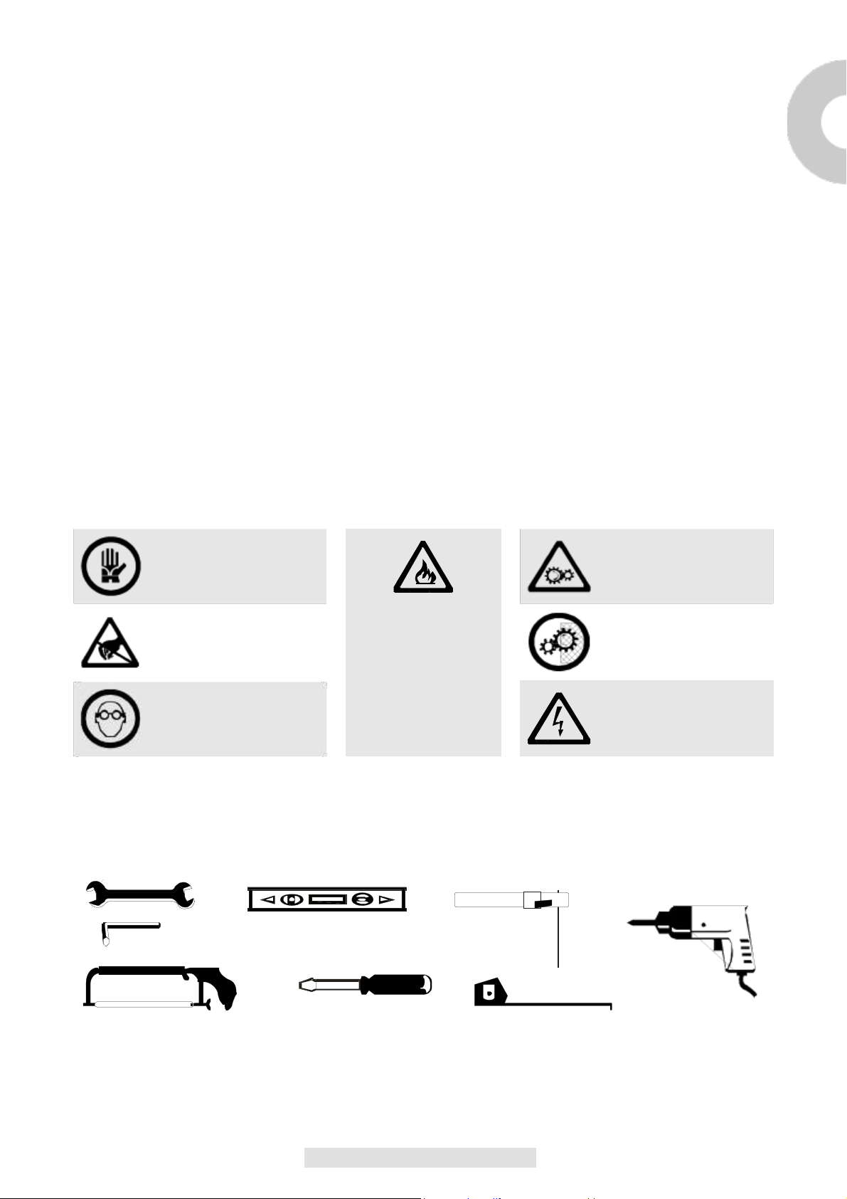
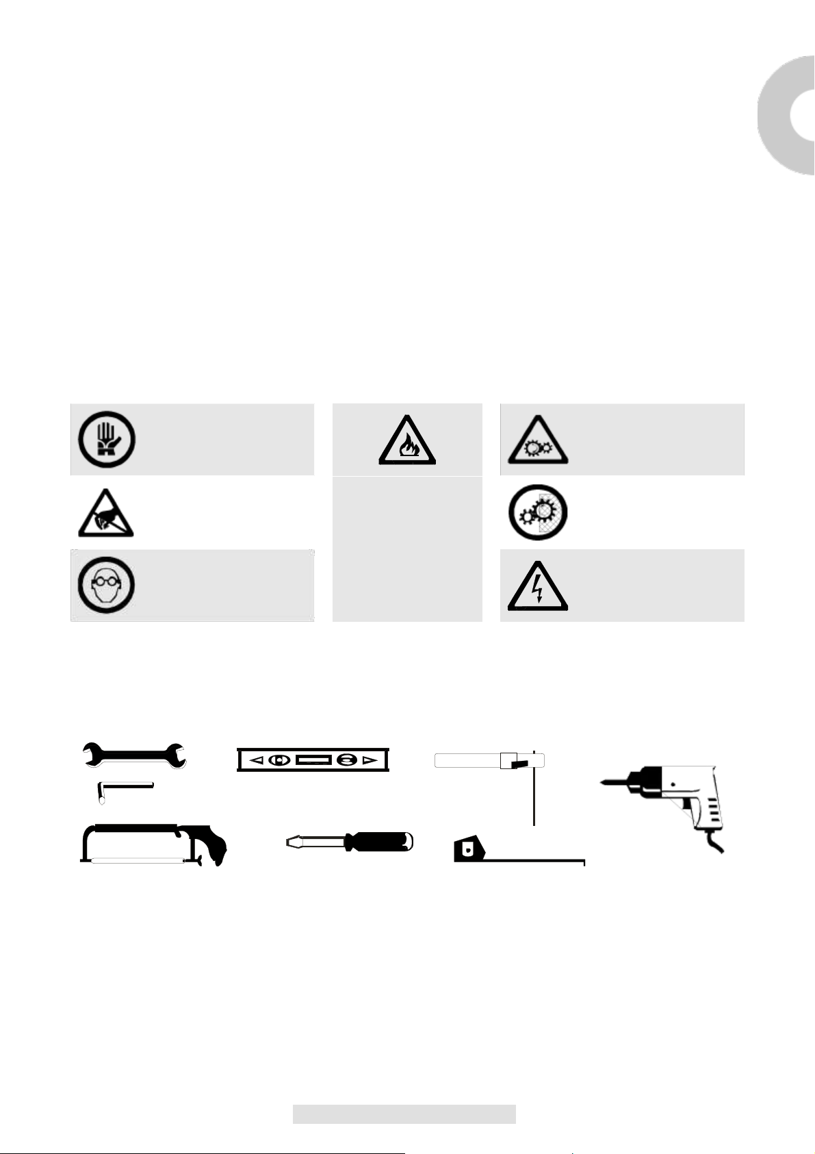
NORME DI SICUREZZA
Durante l’installazione e l’utilizzo dell’automazione seguire con molta attenzione le seguenti norme
di sicurezza:
USARE I GUANTI! ATTENZIONE!
MECCANISMI IN
MOVIMENTO!
ATTENZIONE!
DISTANZA DI
SICUREZZA!
USARE OCCHIALI
PER SALDATURA!
ATTENZIONE! NON
INSTALLARE
L’AUTOMAZIONE
IN
AMBIENTI
SATURI
DI
MISCELE
ESPLOSIVE!
MANTENERE
CARTER DI
PROTEZIONE!
ATTENZIONE!
SHOCK ELETTRICO!
ATTREZZATURA
Per l’installazione dell’automazione è necessaria la seguente attrezzatura: chiavi, cacciavite, metro, bolla,
sega, trapano, saldatrice.

4
MODELLI E CARATTERISTICHE
900SC-400CS Motoriduttore elettromeccanico irreversibile, 4000Vac 4000Kg. Per cancelli
scorrevoli con centralina, con fine corsa magnetico, con predisposizione per
innesto radio e pignone M6.
DATI TECNICI
900SC-400CS
CENTRALINA
CT-380
ALIMENTAZIONE
400Vac
POTENZA ASSORBITA
750W
ASSORBIMENTO MOTORE
2A
GRADO DI PROTEZIONE
Ip54
COPPIA
180NM
VELOCITA’
0.17m/s
FORZA DI SPINTA
3500N
PESO MAX. CANCELLO
4000Kg.
TERMOPROTEZIONE
150°C
CLASSE DI ISOLAMENTO
1
SERVIZIO TEMPORANEO
50%
TEMPERATURA DI ESERCIZIO
-20°C/+70°C
PESO
76Kg.
5
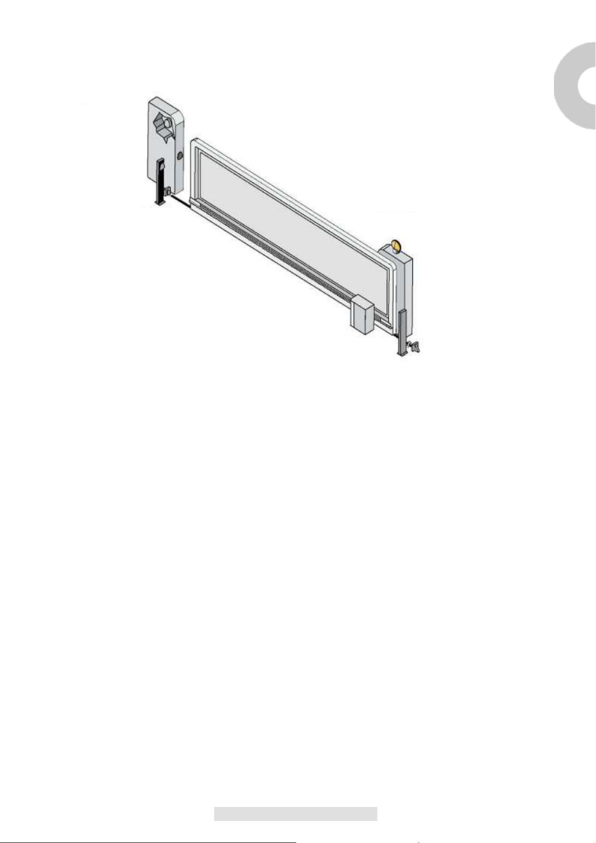
QUADRO D’INSIEME
I
Selettore a
chiave
Fotocellula
Colonnina lampeggiante
motoriduttore
Fig.
1
VERIFICHE PRELIMINARI
Prima di passare all’installazione si consiglia di effettuare le seguenti verifiche ed
operazioni:
1_La
strutturadelcancellodeve
essere
solida
ed
appropriata.
2_Durante
lacorsa,ilcancello
non
devepresentare
eccessivi
sbandamentilaterali.
3_Il sistema di ruote/rotaia inferiore e rulli/guida superiore deve funzionare senza eccessiviattriti.
4_Per evitare il deragliamento del cancello devono essere installate le battute d’arresto delloscorrevole,siain
apertura
siainchiusura,eunsecondorullo/guidasuperiorenel
pieno
rispetto
della
normativavigente.
5_Nei
cancelli
preesistenti
eliminare
l’eventuale serratura
manuale.
6_Portare alla base del cancello le tubazioni di adduzione dei cavi di alimentazione (Ø25-50mm) e di
collegamentoesterno(fotocellula,lampeggiante,selettoreachiave, ecc.).
6
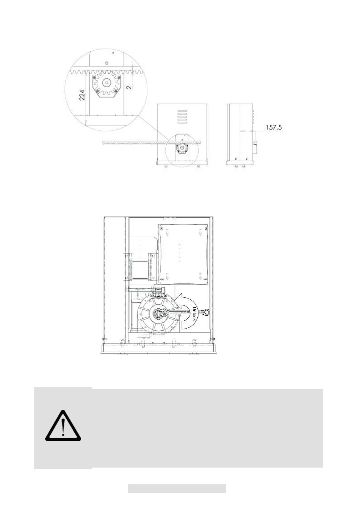
DIMENSIONI D’INGOMBRO
Fig. 2
FUNZIONAMENTO MANUALE
Fig.
3
Per sbloccare il motoriduttore e permettere l’apertura manuale del cancello, si deve utilizzare una chiave
Inglese da 19 mm e ruotare il dado centrale sul riduttore fino a sblocco avvenuto (Fig. 3)
Per ribloccare il motore si ruota in senso opposto il dado. La manovra deve essere fatta a motore fermo.
E’ opportuno leggere attentamente le istruzioni prima di eseguire l’installazione.
La non osservanza delle suddette istruzioni, l’uso improprio o un errore di
collegamento potrebbe pregiudicare la sicurezza o il corretto funzionamento del
dispositivo, e quindi dell’intero impianto.
Si declina ogni responsabilità per eventuali malfunzionamenti e/o danni dovuti
derivanti dalla loro inosservanza.
La ditta si riserva di apportare modifiche migliorative al prodotto.

7
INSTALLAZIONE
Prima di passare all’installazione si consiglia di eseguire le seguenti verifiche oltre ad accertare che la I
struttura sia conforme alle norme vigenti. Nel dettaglio :
Controllare che la parete del muro e/o colonna siano in buone condizioni , altrimenti sarà necessario
rinforzare i punti di fissaggio.
Fare attenzione alla corsa dell’anta non devono esserci ostacoli che ne impediscano il movimento.
L’anta non deve presentare attriti, il movimento sia in apertura sia in chiusura deve essere libero
Se fermata in qualsiasi posizione non deve muoversi. Durante il movimento non deve sbandare.
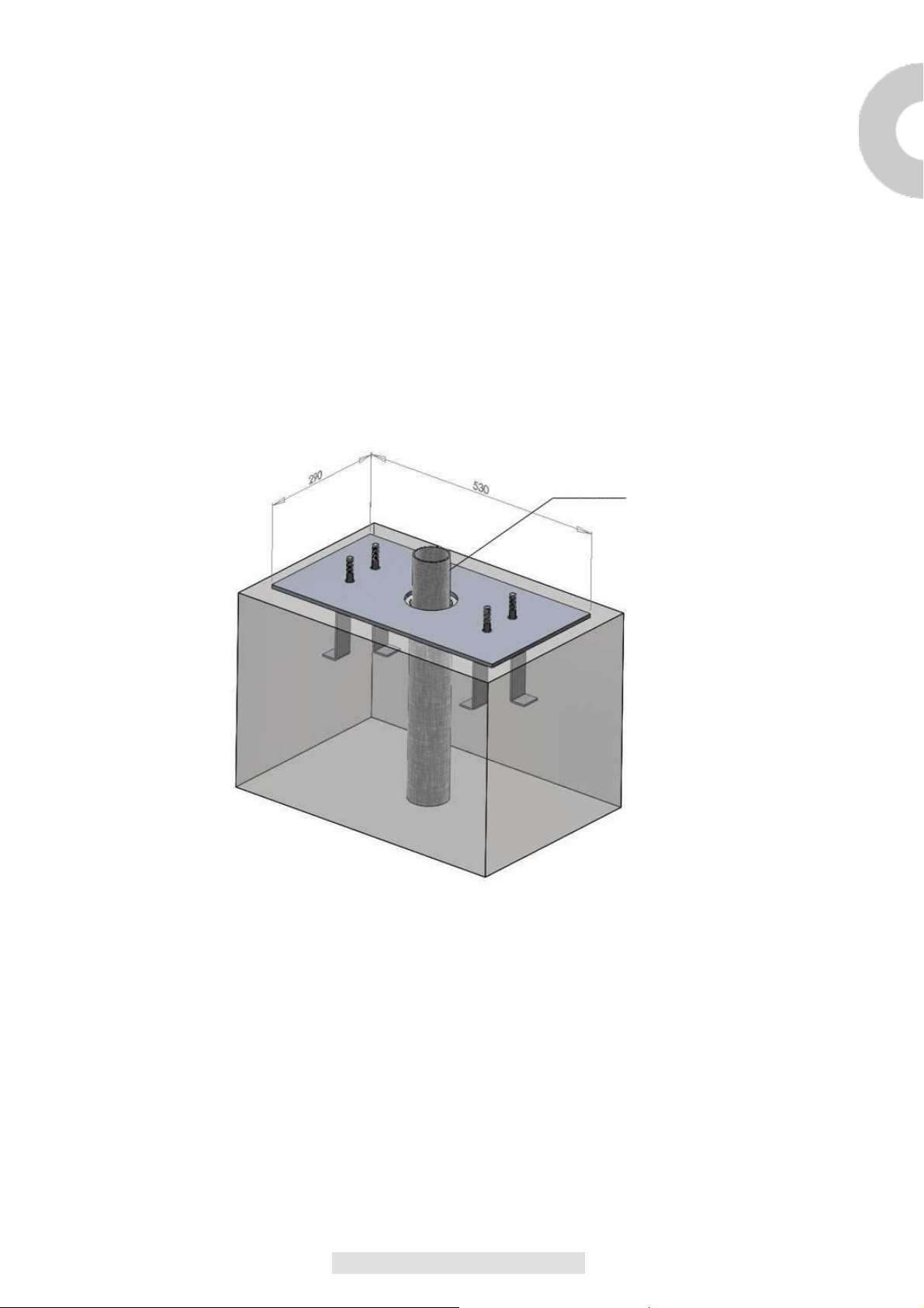
Rispettare le misure di ingombro, creare un solido basamento in calcestruzzo e fissare a terra la
piastra di base annegandola nel calcestruzzo mediante le zanche e viti di fissaggio (fig.4).Sé il
basamento è già esistente utilizzare dei robusti tasselli ad espansione.
Prevedere una o più tubazione per il passaggio dei cavi elettrici.
Tubazione
elettrica
Fig.
4
N.B. E’ NECASSARIO CONOSCERE LE DIMENSIONI DELLA CREMAGLIERA PER POTER CALCOLARE
CON PRECISIONE IL POSIZIONAMENTO DELLA CONTROPIASTRA.

8
FISSAGGIO MOTORIDUTTORE
Aprire l’imballo e verificare che tutti gli elementi che compongono l’automatismo siano integri.
Togliere il coperchio svitando le viti vedi (fig.5).
Appoggiare il motoriduttore sulla piastra.
Inserire le 4 rondelle + dadi autobloccanti per fissare il motore (fig.6).
Qualora la regolazione consentita dalla cremagliera non sia sufficiente è possibile compensare
l’altezza del motoriduttore agendo sulle 4 viti più esterne (fig.6).
Terminata la regolazione fissare energicamente i 4 dadi auto bloccanti, assicurarsi che durante
tutta la corsa del cancello, il motoriduttore sia ben saldo a terra.
TOGLIERE LE
4 VITI M6
Fig.
5
VITI PER REGOLAZIONE ALTEZZA
MOTORIDUTTORE
DADI PER FISSAGGIO
MOTORIDUTTORE
Fig.
6
9
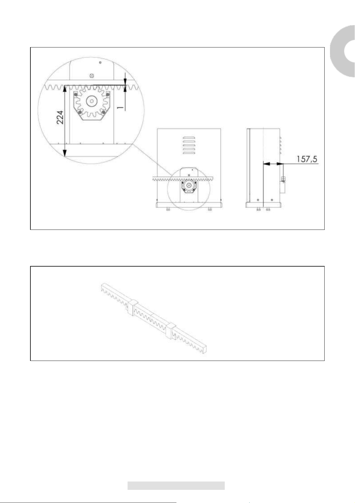
FISSAGGIO CREMAGLIERA
.
I
Fig.
7
Fig.
8
Per una corretta installazione della cremagliera sbloccare il motoriduttore nel modo indicato nella fig. 3
e portare il cancello in completa apertura.
Appoggiare un elemento di cremagliera al pignone e fissare lo stesso con viti e distanziali al cancello.
Spostare manualmente il cancello portando il pignone in corrispondenza dell’ultimo distanziale.
Fissare
l’elemento di cremagliera definitivamente.
Per un corretto posizionamento degli altri elementi e garantire la loro rettilineità è necessario utilizzare un
elemento di cremagliera usandolo come appoggio e riferimento Fig. 8.
Bisogna inoltre garantire un’aria fra cremagliera e pignone di circa 1mm (misura indicativa), così da non far
gravare il peso del cancello sul pignone del motoriduttore come in Fig. 7
10
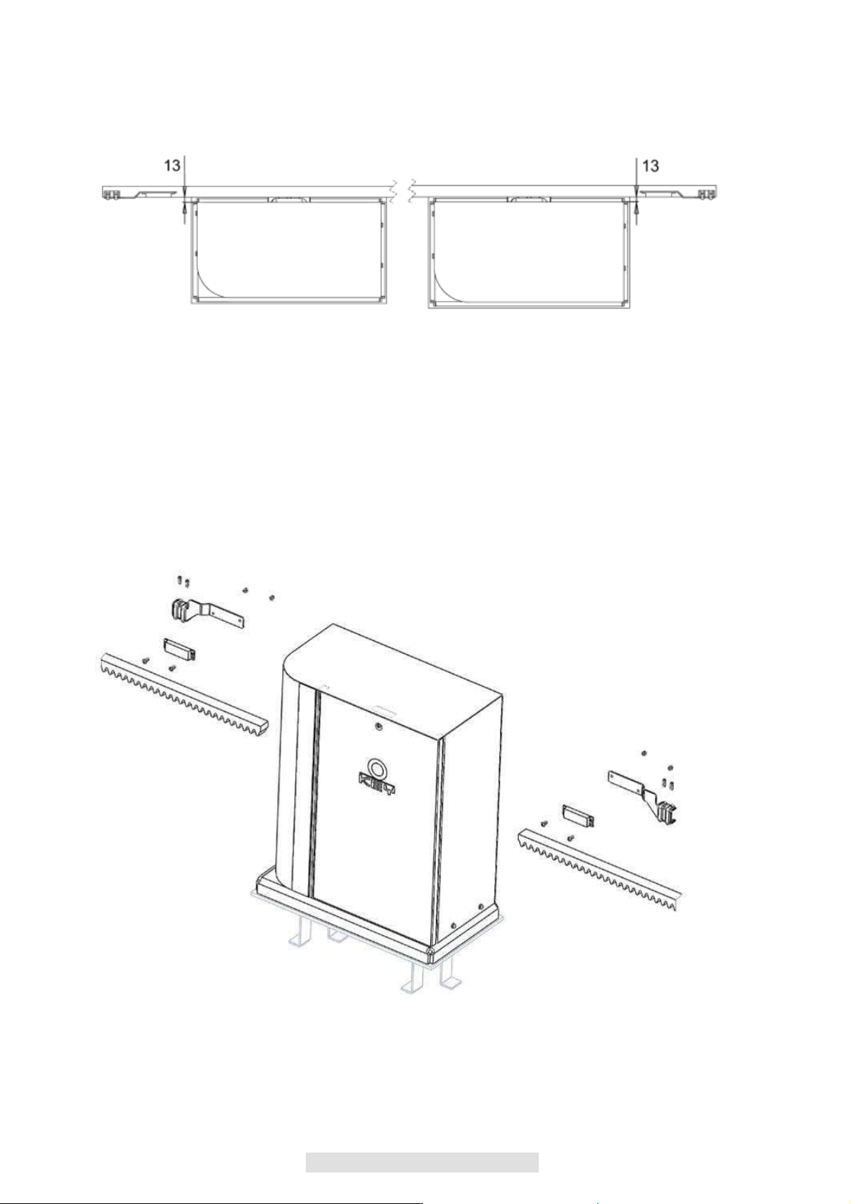
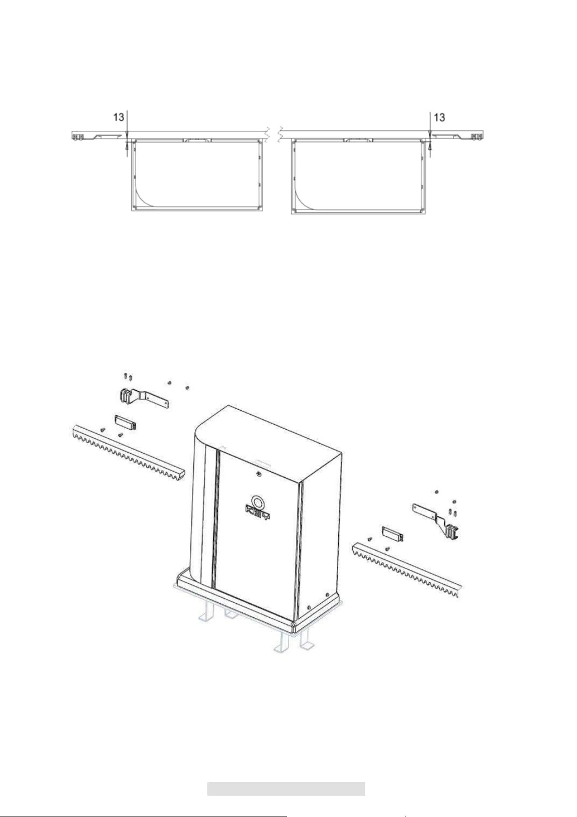
FISSAGGIO FINECORSA
Fig.
9
Il cancello deve essere dotato di fermi d’arresto in apertura e in chiusura che impediscano il
deragliamento del cancello stesso.
La posizione del fermo d’arresto deve garantire che le staffe di fine corsa non entrano in collisione con il
pignone.
Portare manualmente il cancello in apertura lasciando, secondo il peso del cancello, una luce da 30 a
50 mm. tra il cancello stesso e l’arresto meccanico.
Fissare la staffa del finecorsa mediante i grani (fig.10) lasciando una luce tra il fine corsa magnetico e il
motoriduttore di 13 mm circa (fig 9), ripetere l’operazione con il cancello in chiusura.
Fig.
10

11
MANUTENZIONE
PERICOLO: per qualsiasi tipo di manutenzione, togliere l’alimentazione. I
Il motoriduttore è fornito con lubrificazione permanente a grasso e quindi non
necessita di manutenzioni.
Cavi, molle e supporti non necessitano di manutenzione periodica.
In caso di mal funzionamento il sistema non deve essere utilizzato e bisogna
rivolgersi al personale specializzato.
AVVERTENZE GENERALI
Fissare le etichette che mettono in guardia contro lo schiacciamento in un punto molto visibile o in
prossimità di comandi fissi;
Fissare in modo permanente le etichette relative al rilascio manuale e apporle vicino all’organo di
manovra;
Le marcature devono essere visibili anche dopo l’installazione del dispositivo. Altrimenti se la
marcatura può risultare nascosta dopo l’installazione essa deve essere riportata nelle istruzioni.
I motori di movimentazione devono essere forniti di un’etichetta che indichi di tenere i bambini lontano
dalla porta in movimento, oppure mettere l’apposito simbolo (ISO 3864, vedi simbolo)
RACCOMANDAZIONI FINALI
Tenere il telecomando lontano dalla portata dei bambini e non permettere loro di giocare con i dispositivi
di comando.
Dotare l’impianto di dispositivi di sicurezza come: fotocellule e costola sensibile.
Realizzare l’impianto secondo le norme vigenti.
E’assolutamente necessario che prima dell’installazione del motoriduttore, il cancello sia dotato
delle battute di arresto.
Tutti gli interventi di manutenzione, riparazione e regolazione devono essere eseguiti da personale
qualificato.
I motori con sistema sensibile alla pressione devono essere forniti di un’etichetta che indichi:
ATTENZIONE RISCHIO DI SCHIACCIAMENTO.
SMALTIMENTO
L’eliminazione dei materiali va fatta rispettando le norme vigenti.

12
INDEX
SAFETY............................................................................................................................................................13
EQUIPMENT ....................................................................................................................................................13
MODELS AND
CHARACTERISTICS
..............................................................................................................14
OVERALL VIEW ..............................................................................................................................................15
PRELIMINARY CHECKS.................................................................................................................................15
DIMENSIONS
...................................................................................................................................................16
MANUAL
OPERATION
....................................................................................................................................16
INSTALLATION ...............................................................................................................................................17
FIXING OF REDUCTION
GEAR
......................................................................................................................18
FIXING OF RATCHET......................................................................................................................................19
FIXING LIMIT
DEVICE
.....................................................................................................................................20
MAINTENANCE...............................................................................................................................................21
FINAL RECOMMENDATIONS ........................................................................................................................21
DISPOSAL .......................................................................................................................................................21
SPARE PARTS CATALOGUE ........................................................................................................................62
LIST OF SPARE PARTS .................................................................................................................................63
THIS BOOKLET IS TO BE USED ONLY BY THE INSTALLER
Installation must be carried out only by professionally qualified personnel in compliance with current legal
requirements.
13
SAFETY
Congratulations on your choice of our product.
This manual will aid you in installing your reduction gear.
GB
As you read through it, you will find not only explanations on the operation of the reduction gear, but also on
safety standards that you must comply with for perfect operation and maximum safety.
To prevent damage to your unit and to avoid injury to yourself or others, before installing the reduction gear
and its components, carefully read all of the following information on safety standards.
Keep this information so that anyone who will be using the unit can refer to it.
No liability shall be accepted for the consequences of failure to comply with the precautions provided.
! If the unit malfunctions, shut it off immediately.
! When making repairs, make sure the electrical supply is disconnected.
! Do not attempt to disassemble the unit if you are not an authorized installer.
! Do not expose to flames or sources of heat. Do not immerge in water or other liquids.
! Use suitable power cables.
! Supervise the door when it is moving. Keep people away from it until it is completely open or closed.
SAFETY STANDARDS
During installation and use of this automation, carefully follow these safety standards:
USE GLOVES!ATTENTION!
MECHANISMS IN
MOVEMENT!
ATTENTION!
SAFE DISTANCE!
USE WELDING
GOGGLES!
ATTENTION! DO
NOT INSTALL THE
AUTOMATION IN
ENVIRONMENTS
THAT
ARE
SATURATED
WITH
EXPLOSIVE
MIXTURES!
LEAVE GUARD IN
PLACE!
ATTENTION!
ELECTRICAL SHOCK!
EQUIPMENT
To install the automation, you will need the following equipment: wrenches, screwdrivers, tape measure,
level, saw, drill, welder.

14
MODELS AND CHARACTERISTICS
900SC-400CS Irreversible electro-mechanical reduction gear, 4000Vac 4000Kg. For sliding
gates with control unit and magnetic limit devices, with the predisposition of
installing a radio control device and M6 pinion.
TECHNICAL DATA
900SC-400CS
CONTROL UNIT
CT-380
POWER SUPPLY
400Vac
INPUT POWER
750W
MOTOR ABSORPTION
2A
DEGREE OF PROTECTION
Ip54
TORQUE
180NM
SPEED
0.17M/S
THRUST FORCE
3500N
MAX WEIGHT GATE
4000Kg.
THERMAL PROTECTION
150°C
INSULATION CLASS
1
TEMPORARY SERVICE
50%
OPERATING TEMPERATURE
-20°C/+70°C
WEIGHT
76Kg.

15
OVERALL VIEW
GB
Key selector
Photocell
Bollard flashing light
gear motor
Fig.
1
PRELIMINARY CHECKS
Before starting installation it is recommended to carry out the following checks and
operations:
1_The structure of the gate must be solid and appropriate.
2_During the run, the gate must not present excessive side disbandment.
3_The lower wheels/rail and the higher roller/guide systems must work without excessive friction.
4_To avoid the disbandment of the gate, sliding gate check stops, both in aperture and in closure, and a
second higher roller/guide must be installed in compliance with current regulations.
5_In pre-existing gates remove any manual lock.
6_Lay the ducts for the energy supply (Ø25-50mm) and for the outside connection (photocell, flashing
device, key selector, etc.) to the base of the gate.

16
DIMENSIONS
Fig. 2
MANUAL OPERATION
Fig.3
To unlock the gear motor and permit manual aperture of the gate, use a 19 mm wrench and turn the central
nut on the gear motor until unlocking occurs (Fig. 3). To relock the motor, turn the nut in the opposite
direction. This manoeuvre must be carried out with the motor stopped.
It is advisable to read the instructions carefully before you start installation.
Failure to comply with these instructions, improper use or incorrect connection may
compromise the safety or correct operation of the device and hence of the entire
system.
No liability shall be accepted for any malfunctions and/or damage due to failure to
comply with the instructions.
The company reserves the right to make improvements to the products.
17
INSTALLATION
Before starting installation, you should carry out the following checks, as well as making sure the structure is
GB
compliant with current standards. Specifically:
Check that the wall and/or column are in good condition. If they are not, the fastening points will need
to be reinforced.
Make sure that the travel of the shutter is not obstructed in any way. The shutter must not have
friction, the movement in aperture and in closure must be free If stopped in any position it must not
move. During movement it must not slip.
Follow the dimensions, create a solid concrete footing and fix the base plate to the ground immerging
it into the concrete using the bracket clamps and fixing screws (fig.4). If the base already exists use
robust expanding wedges.
Provide one or more pipelines for the laying of electrical cables.
Electrical
pipeline
Fig.4
N.B. IT IS NECESSARY TO KNOW THE DIMENSIONS OF THE RATCHET IN ORDER TO CALCULATE
WITH PRECISION THE POSITION OF THE COUNTER-PLATE.

18
FIXING OF REDUCTION GEAR
Open the packaging and check the condition of all the parts of the automation.
Remove the lid unscrewing the screws see (fig. 5).
Place the reduction gear on the plate.
Insert the 4 washers + locknuts to fix the gear (fig. 6).
If the allowed adjustment of the ratchet is not sufficient it is possible to compensate the height of the
reduction gear working on the 4 more external screws (fig.6).
Once the adjustment is finished firmly fix the 4 locknuts, making sure that during the entire run of the
gate, the reduction gear is firmly to the ground.
REMOVE THE
4 M6 SCREWS
Fig.
5
SCREWS FOR THE HEIGHT
ADJUSTMENT OF THE
REDUCTION GEAR
NUTS FOR FIXING THE
REDUCTION GEAR
Fig.
6

19
FIXING OF RATCHET
.
GB
Fig.
7
Fig.
8
For the correct installation of the ratchet unlock the reduction gear as shown in fig. 3 and bring the gate to
complete aperture.
Lay one element of the ratchet on the pinion and fix the latter with screws and tingles to the gate.
Manually move the gate bringing the pinion in correspondence with the last tingle. Definitively fix the element
of the ratchet.
For the correct positioning of the other elements and to ensure they are straight it is necessary to use a
ratchet element using it as reference and support Fig. 8.
Moreover it is necessary to ensure some air between the ratchet and the pinion of about 1 mm(indicative
measure), so that the weight of the gate does not bear upon the pinion of the reduction gear Fig. 7.
20
FIXING LIMIT DEVICE
Fig.
9
The gate must feature check stops for aperture and closure that prevent the gate from derailing.
The position of the check stop must ensure that the limit devices do not collide with the pinion.
Manually open the gate leaving, based on the weight of the gate, a space between 30 and 50 mm. between
the gate and the mechanical stop.
Fix the limit device using the pins (fig. 10) leaving a space between the magnetic limit device and the
reduction gear of approximately13 mm (fig 9), and repeat the operation with the gate closed.
Fig.10
Table of contents
Languages:
Other Allmatic Garage Door Opener manuals


