Pag. 23 di 36 E
N
G
L
I
S
H
GRADUAL START
Upon gate operation command, a gradual start is performed, as default, for 1 sec.
ELECTRONIC BRAKE
In case the slowing mode is not used (dip 8 ON), enabling of dip 7 (ON) is recommended.
In this way the electronic brake will cope for the gate inertia on approach of the travel stop
switches.
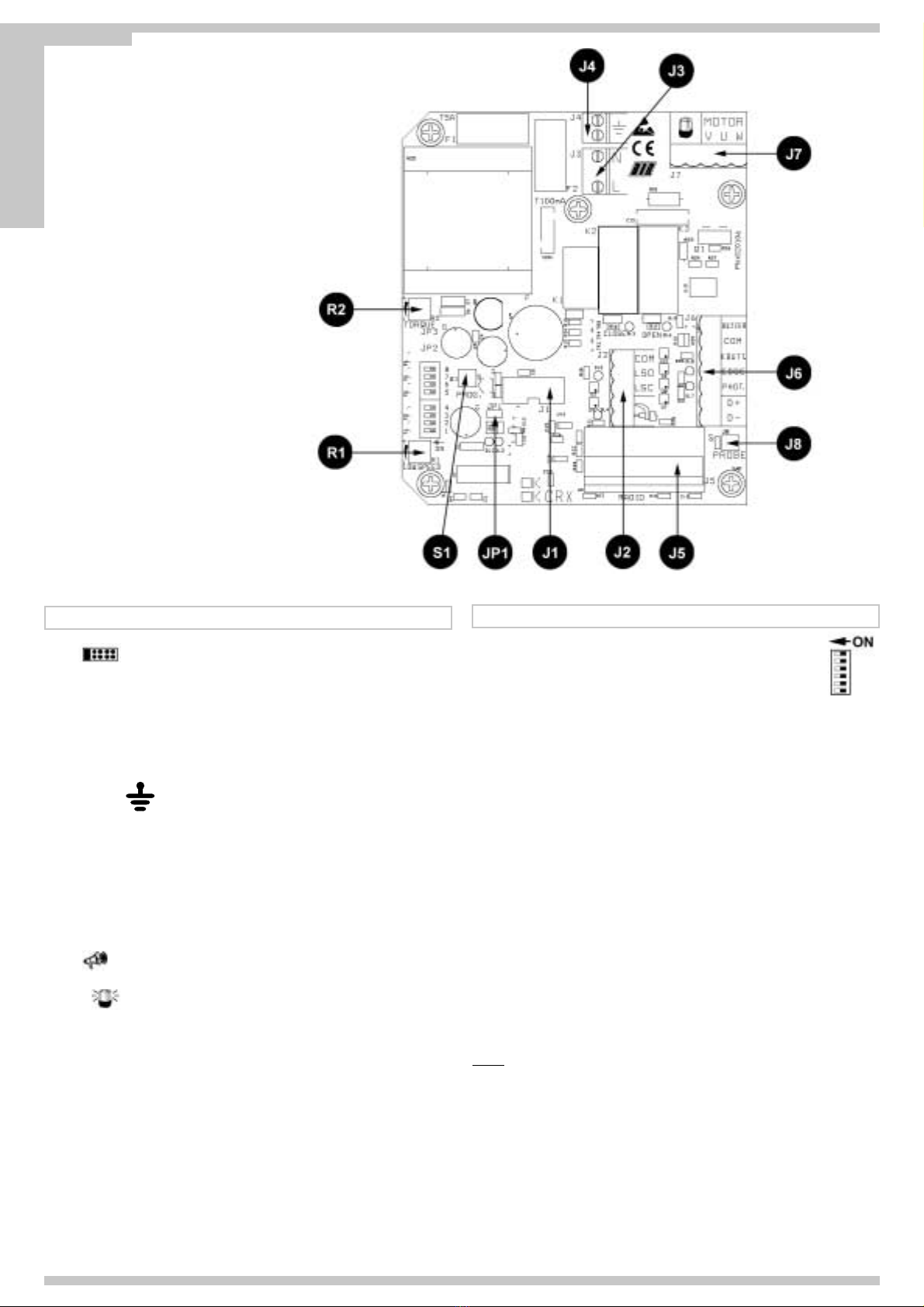
LED SIGNALS
DL1 - (Red) - Programming operated
DL2 - (Green) - Radio programming activated (models CRX only)
DL3 - (Red) - Opening limit switch contact (NC)
DL4 - (Red) - Closing limit switch contact(NC)
DL5 - (Red) - Gate on closure
DL6 - (Green) - Gate on opening
DL7 - (Red) - Photocells contact (NC)
DL8 - (Red) - afety strips contact (NC)
C – CHECKING THE ROTATION DIRECTION OF THE MOTOR
This control is carried out to facilitate the installation of the system or any possible future
control.
1 - After you have ensured the correct positioning of the limit switch (fig.7) manually move
the gate to half open position;
2 - Put DIP 1 in the ON mo e => The LED DL1 starts blinking;
3 - Press the PROG button and hold it (the gate now is controlled in a dead man mode:
open, stop close stop open-etc...) => THE RED LED DL5 "CLOSE" comes on an
the gate starts closing (if it does not close, invert the wires of the motor V and W)
until it reaches the limit switch of the close position (if the gate and motor do not stop,
release the PROG button and invert the position of the cables L O and L C);
4 - Press the PROG button and hold it => THE GREEN LED DL6 "OPEN" comes on
an the gate opens until it reaches the limit switch for opening position;
5 - After 2 sec. an within 10 sec. of continuous work, both in closing or opening,
the electronic clutch intervenes automatically. A just the force of the clutch by
turning the appropriate trimmer “TORQUE”.
6 - After 10 sec. of continuous work, both in opening an closing, the automatic
eceleration is activate (if DIP 8 is on OFF position) A just the spee of the
operator requeste uring the eceleration by turning the appropriate trimmer
“LOW SPEED”.
7 - At the en of the control, an of the trimmers’ a justements, position DIP1 on
mo e OFF. The LED DL1 turns off, signalling you exit from the control.
NB: The safety edges and the photocells are not active during this control.
D - TIMING
The programming can be carried out regardless of the gate position.
1 - Put DIP 2 in the ON mode => the LED DL1 emits short blinkings.
2 - Push the button PROG. => the gate opens closes and opens automatically 2 seconds
after It closed. When the opening cycle Is terminated, It stops. Wait as long as you
want the gate to remain open (excluded by DIP3 OFF)
3 - Push the button PROG. to command the gate closing (also the pause time count
before the automatic closing stops - max. 5 minutes).
4 - The gate stops as the closing limit switch is reached.
5 - AT THE END OF THE PROGRAMMING PUT THE DIP 2 BACK ON OFF.
DURING THE PROGRAMMING THE SAFETIES ARE ACTIVE AND THEIR
INTERVENTION STOPS THE PROGRAMMING (THE LED DL2 WHICH WAS
LIGHTENING NOW HAS A COSTANT LIGHT). TO REPEAT THE PROGRAMMING
SET THE DIP 2 ON OFF AND REPEAT THE PROGRAMMING DESCRIBED ABOVE.
NOTE: The deceleration speed is set automatically by the control panel during the time
programming. The deceleration starts automatically about 15-20 cm before the
gate reaches the limit switch in opening and closing.
E – RADIO CODE LEARNING PROCEDURE
(CRX MODELS ONLY)
1 - The position of the gate does not affetc the code memorisation.
PLEASE NOTE: if DIP3 is in ON position (pause time before automatic closing)the code
memorisation cannot be carried out with the gate in completely open
position.
2 - et DIP 1 - ON and subsequently DIP 2 - ON => DL1 programming led will lighten with
a frequency of 1 sec. ON e 1 sec. OFF for 10 seconds, witch is the time required for
they code’s programming.
3 - Press the remote control button (normally the A channel) within the 10 set seconds. If
the remote control is correctly read in, the DL2 green led emits a flashing.
4 - The codes’ programming time is automatically renewed to read in the following remote
control.
5 - To end the programming wait 10 seconds, or press for a while the PROG. button =>
DL1 programming led will stop lightening.
6 - Re-set DIP 1 - OFF and DIP 2 - OFF.
7 - End of the procedure.
RADIO CODES CANCELLATION PROCEDURE
The position of the gate does not affetc the code memorisation.
PLEASE NOTE: if DIP3 is in ON position (pause time before automatic closing) the code
memorisation cannot be carried out with the gate in completely open
position.
1 - et DIP 1 - ON and subsequently DIP2 - ON.
2 - DL1 programming led will lighten with a frequency of 1 sec. ON and 1 sec. OFF for 10
seconds.
3 - During the 10 seconds => press and keep pressed the PROG. Button for 5 seconds
=> the memory cancellation is signalled by two flashings of the DL2 green Led.
4 - ubsequently DL1 programming led stays active and it is possible to add new codes
following the procedures described above.
MEMORY SATURATION SIGNALING
The position of the gate does not affetc the code memorisation.
PLEASE NOTE: if DIP3 is in ON position (pause time before automatic closing)the code
memorisation cannot be carried out with the gate in completely open
position.
1 - By setting DIP 1 - ON and subsequently DIP 2 -ON.
2 - DL2 green Led lightens for 6 times thus signalling that the memory is full (60 codes
available).
3 - ubsequently the DL1 programming led stays active for 10 seconds, thus enabling the
possible total cancellation of the codes.
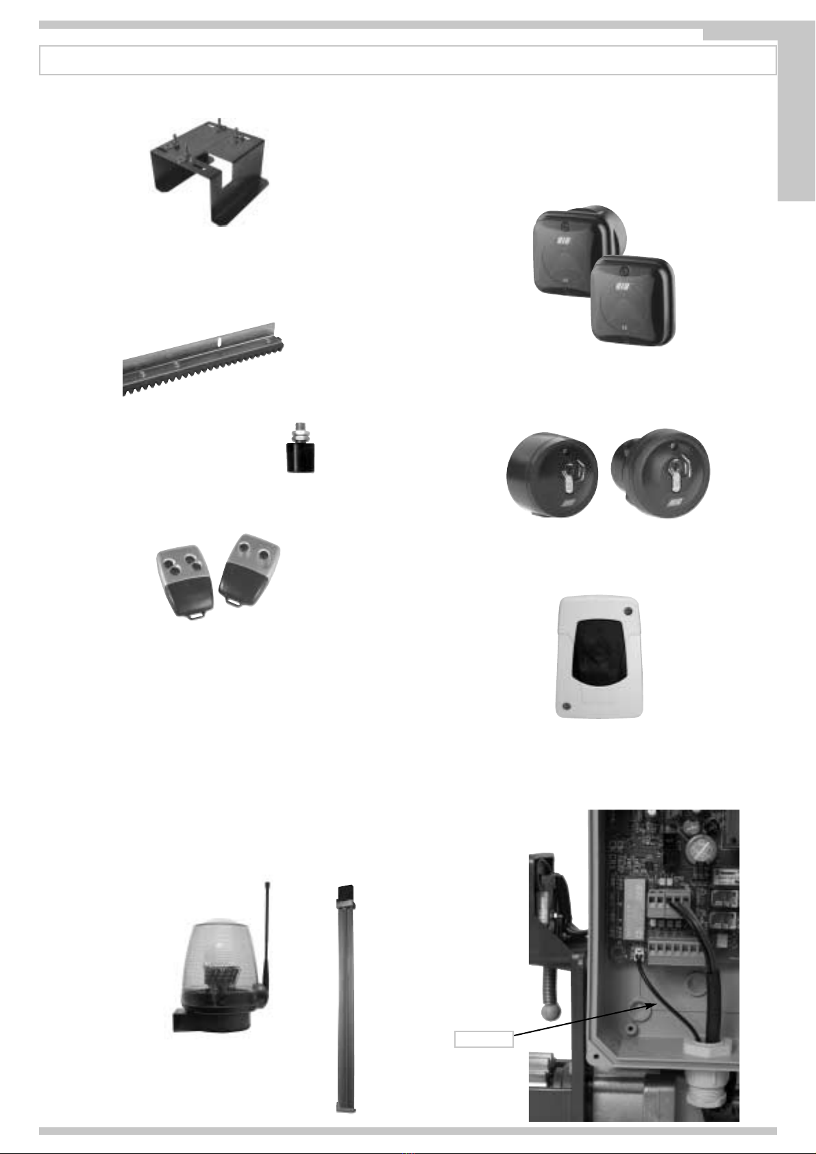
OPERATION OF THE OPERATING ACCESSORIES
OPERATION BUTTON (COM-K BUTTON)
If DIP6 is ON => It cyclically commands open-stop-close-stop-open-etc.
If DIP6 is OFF => It opens the gate when this is closed. If it is operated while the gate Is
opening, it has no effect.
If it is operated when the gate is open, it closes the gate and, if it is operated while the
gate is closing, it opens the gate again.
TIMER FUNCTION (automatic operation mo e only DIP 6 OFF)
This function is useful In the rush hours, when vehicle traffic is slow (e.g. entry/exit of
workers, emergencies In residential or parking areas and, temporary, for removals).
APPLICATIONS
By connecting a switch and/or a daily/weekly timer (in place or in parallel with the opening
button N.O. “COM-K BUTTON”), it is possible to open the gate or to keep it open, as long
as the switch is on or the timer is activated.
When the gate is open, all operating functions are inhibited.
On switch release, or at set time, the actuator will close.
RADIO TRANSMITTER
If DIP6 is ON => It cyclically commands open-stop-close-stop-open-etc.
If DIP6 is OFF => It opens the gate when this is closed.
If it is operated while the gate is opening, it has no effect.
If it is operated when the gate is open, it closes. If it is operated while the gate is closing, it
opens the gate again.
AUTOMATIC CLOSING FOR COMPLETE OPENING
The pausing time before the automatic closing for complete opening is set during the time
programming. The maximum pausing time available is 5 minutes. Pause time can be
started or stopped by DIP3 (ON started).
RESTORING OF OPERATION FOLLOWING A BLACK OUT FAILURE
Following a black out, and on resuming of power supply, the gate will operate as indicated
on table TAB1, at the following page.