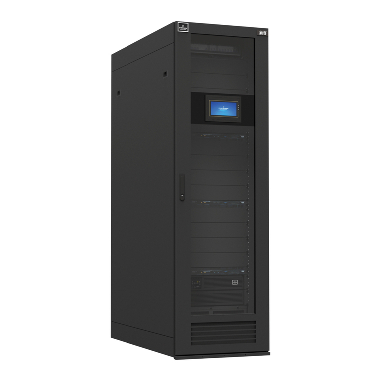
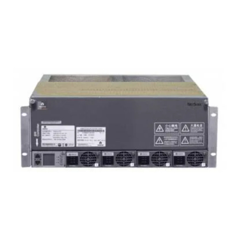
Vertiv Tech NetSure 731 CC2 Series User manual

NetSure 731 CC2、NetSure 731
C62 系列电源系统
用户手册
NetSure731CC2, NetSure731C62
SeriesPowerSupplySystem
User Manual
资料版本 V2.0
归档时间 2017-12-31
BOM 编码 31013521
Version V2.0
Revision date December 31, 2017
BOM 31013521
维谛技术有限公司为客户提供全方位的技术
支持,用户可与就近的维谛技术有限公司办事
处或客户服务中心联系,也可直接与公司总部
联系。
维谛技术有限公司
版权所有,保留一切权利。内容如有改动,恕
不另行通知。
维谛技术有限公司
地址:深圳市南山区学苑大道 1001 号南山智
园B2 栋
邮编:518055
公司网址:www.vertivco.com
客户服务热线:4008876510
E-mail: vertivc.service@vertivco.com
Vertiv Tech provides customers with technical
support. Users may contact the nearest Vertiv local
sales office or service center.
Copyright © 2017 by Vertiv Tech Co., Ltd.
All rights reserved. The contents in this document
are subject to change without notice.
Vertiv Tech Co., Ltd.
Address: Block B2, Nanshan I Park, No.1001
Xueyuan Road, Nanshan District, Shenzhen,
518055, P.R.China
Homepage: www.vertivco.com
E-mail: overseas.support@vertivco.com

Declaration
This is a Class AUPS product.In a residentialenvironment,this productmaynevertheless cause radio
interference,in whichcase,the user is required totake additionalmeasurestoreduce theinterference.
Safety Precautions
To reducethe chanceof accident,pleaseread thesafety precautions verycarefullybeforeoperation.The
'Caution,Note, Warning, Danger'in this book and on the productdo not representall the safety points tobe
observed,andare onlysupplementtovarious safety points.Therefore,the installationandoperationpersonnel
mustreceive strict trainingandmasterthecorrect operations andallthesafety points before operation.
When operating Vertiv products,the operationpersonnelmustobserve the safetyrules in the industry, the
generalsafetypoints andspecialsafetyinstructions provided byVertiv.
Electrical Safety
I. Hazardous voltage
Danger
Danger
Some components of the pow er systemcarryhazardousvoltagein operation.Direct contactor
indirect contact throughmoist objects withthesecomponents willresultinfatalinjury.
Observe safetyrules inthe industrywheninstalling thepowersystem.The installation personnelmustbe
licensedtooperatehighvoltage andAC power.
In operation,the installationpersonnel arenotallowed towear conductiveobjects,suchas watches,bracelets,
bangles andrings.
When you spotthe cabinetwith water or moisture,turnoff the powerimmediately.In moistenvironment,
precautions mustbetakento keep moistureoutof the powersystem.
’Prohibit’ warning label must be attached to the switches and buttons that are not permi ttedtooperate during
installation.
Danger
Danger
High voltageoperation may causefireandelectricshock.The connectionandwiringof ACcables
must be in compliance withthelocal rules and regulations.Only thosewhoarelicensedtooperate
high voltage andACpower canperformhighvoltage operations.
II. Tools
Warning
In high voltageand ACoperation,specializedtools must be used.
III. Thunderstorm
Danger
Danger
Never operate on high voltage,AC, irontow er or mast in the thunderstorm.
In thunderstorms,astrongelectromagneticfieldwill begeneratedin the air. Therefore the equipmentshould be
wellearthedin timeto avoid damagebylightningstrikes.
IV. ESD
Note
The static electricity generatedby the human body willdamage the static sensitiveelements on PCBs,
suchas large-scaleICs. Beforetouchingany plug-in board,PCB orIC chip,ESD wriststrapmustbe
worntopreventbodystatic fromdamaging thesensitivecomponents.The other endof the ESD wrist
strapmust be wellearthed.

V. Short circuit
Danger
Danger
During operation, nevershortthepositiveand negativepoles of theDC distributionunit of the
power systemor thenon-groundingpole and the earth.The power systemisaconstant-voltage
DC power device,shortcircuitwillresultin equipment burningand endanger human safety.
Checkthe polarityof the cableandconnection terminal whenperformingDCliveoperations.
As the operationspace inthe DC distributionunitis very tight,pleasecarefullyselectthe operationspace.
Never wear a watch, bracelet,bangle,ring, or otherconductive objects duringoperation.
Useinsulated tools.
In live operation,keepthe arm,wristand hand tense,sothat when the tool inoperationslips,the movementof
the humanbodyand tool is reducedto a minimum.
Battery
Danger
Danger
Beforeany operationon battery, readcarefully thesafety precautions forbattery transportationand
the correctbattery connectionmethod.
Note
If the pow er systemdoes not connectwithmains power for alongtime, to prevent battery
over-discharge, users should cut batteries off fromthepow er systemthoroughly, for example, pulling
out battery fuses orswitchingoffbattery MCBs.Before puttingthe power systemintooperation,insert
all thebattery fuses or switchonallthe battery MCBs.
Non-standardoperationon thebattery willcausedanger.In operation,precautions shouldbe takento prevent
batteryshort circuit and overflow of electrolyte. The overflow of electrolyte will erode themetal objects and PCBs,
thus causing equipmentdamage andshortcircuitofPCBs.
Before anyoperationonbattery, pay attentionto the followingpoints:
1. Removethe watch, bracelet,bangle,ring,and othermetalobjects onthe wrist.
2. Use specialized insulated tools.
3. Useeye protectiondevice, and take preventive measures.
4.Wear rubbergloves and apronto guardagainstelectrolyteoverflow.
5. In battery transportation,theelectrodeof the battery shouldalways be keptfacing upward.Never put the
battery upside downorslanted.
LLVD And BLVD
The powersystem has batterylowvoltage disconnection(BLVD)function and loadlowvoltage disconnection
(LLVD) function. LLVD means thatthe mains failandbatteries supplypower, the controllercuts the non-priority
loadoff whenthe battery voltage drops downto below44V. In this way, the battery remainingcapacitycan
sustainthepriorityload longer.BLVD means thatthecontrollercuts the loadoff whenthe battery voltage drops
downto 43.2V to prevent over-discharge.
The factory settingis enablingLLVD and BLVD, whichmeans thatif poweroutagelasts fora longtimeor the
powersystem fails,theremightbeLLVD andBLVD. Users shouldclassifytheloads and connectthe non-
priorityloads to LLVD routes,and connectthe priorityloads to BLVD routes.For vital loads,users can disable
BLVD of these loads toinsure reliabilityof the powersupply.
The method of disabling BLVDis:
1. Hardwaredisabling:unplugthesignalcable inJ10interfaceof the controller.Tag the BLVD-disabled label.
The positionofthe controllerand the interface descriptionaregivenin 2.4.2 ConnectingSignal Cables.
2. Software disabling:set‘BLVD Enable’item of the controllerto ‘N’.

Note
The advantageof enabling BLVDis protectingthebatteries fromover-dischargewhenthebattery
voltageis low.Thedisadvantageof enabling BLVDis that w henthebattery voltagedrops downtoa
certainvalue,all the loads (including non-priority loads and priority loads) willbecutoff dueto battery
disconnection.
The advantageof softwaredisablingBLVDis prolonging the powersupplyof priority loads.The
disadvantage is that softwaredisablingcannotpreventunwantedpowerfailure duetomisoperation or
power systemfailure.
The advantageof hardwaredisablingBLVDispreventingunwantedpowerfailureduetomisoperation
or pow er systemfailure,andensuringthe continuity of vital loads’pow er supply.
Others
I. Sharp object
Warning
When moving equipment by hand, w ear protectivegloves toavoidinjury by sharpobject.
II. Power cable
Note
Please verify thecablelabels beforeconnection.
III. Signal cables
Note
The signal cables shouldbe routedat least 150mm away frompowercables.
Note
Note
To preservetheenvironment,the busbar of thepower systemmay use tinning techniqueor
passivationtechnique.The busbarmay become darkdue to long-termoperation,w hichdoesnot
influence theperformanceor use of the power system.

Contents
Chapter 1 Overview................................................................................................................................................................................1
1.1 Model Description...................................................................................................................................................................1
1.2 Composition And Configuration............................................................................................................................................1
1.3 Features....................................................................................................................................................................................6
1.4 Operating Principle.................................................................................................................................................................6
1.5 Functions..................................................................................................................................................................................6
1.5.1 Lightning And Surge Protection...............................................................................................................................6
1.5.2 LLVD And BLVD.........................................................................................................................................................8
1.5.3 Fault Alarm And Protection.......................................................................................................................................8
1.5.4 AC And DC Distribution.............................................................................................................................................8
1.5.5 Earthing Design..........................................................................................................................................................9
Chapter 2 Installation Instruction.......................................................................................................................................................10
2.1 SafetyRegulations...............................................................................................................................................................10
2.2 Preparation............................................................................................................................................................................10
2.3 Mechanical Installation........................................................................................................................................................11
2.3.1 Installing Power Cabinet.........................................................................................................................................11
2.3.2 Installing Rectifiers..................................................................................................................................................12
2.4 Electrical Installation............................................................................................................................................................12
2.4.1 Connecting Power Cables .....................................................................................................................................12
2.4.2 Connecting Signal Cables......................................................................................................................................14
2.4.3 Bottom Cabling Cabinet.........................................................................................................................................17
Chapter 3 Testing.................................................................................................................................................................................19
3.1 Installation Check And Startup ..........................................................................................................................................19
3.2 Basic Settings.......................................................................................................................................................................20
3.3 Alarm Check And System Operation Status Check.......................................................................................................20
3.4 Final Steps............................................................................................................................................................................21
Chapter 4 Use Of The Controller.......................................................................................................................................................22
4.1 Operation Panel...................................................................................................................................................................22
4.2 Main LCD Screens...............................................................................................................................................................22
4.2.1 System Information Screen...................................................................................................................................22
4.2.2 Password Confirmation Screen.............................................................................................................................23
4.2.3 MAINMENU Screen................................................................................................................................................23
4.2.4 STATUS Screen......................................................................................................................................................24
4.2.5 Settings Screen.......................................................................................................................................................24
4.2.6 Maintenance Screen...............................................................................................................................................24
4.2.7 EnergySaving Screen............................................................................................................................................25
4.2.8 Fast Settings Screen...............................................................................................................................................25

4.3 Querying System Main Information...................................................................................................................................25
4.4 Querying Rectifier Status....................................................................................................................................................27
4.5 Querying Alarm Information...............................................................................................................................................27
4.5.1 Querying Active Alarm............................................................................................................................................27
4.5.2 Querying History Alarm..........................................................................................................................................29
4.6 Maintenance.........................................................................................................................................................................29
4.7 Setting Parameters..............................................................................................................................................................30
4.7.1 Alarm Settings..........................................................................................................................................................30
4.7.2 BatterySettings.......................................................................................................................................................32
4.7.3 AC Settings...............................................................................................................................................................37
4.7.4 DC Settings..............................................................................................................................................................37
4.7.5 Rectifier Settings.....................................................................................................................................................38
4.7.6 System Settings.......................................................................................................................................................39
4.7.7 Communication Settings........................................................................................................................................39
4.8 EnergySaving Settings.......................................................................................................................................................40
4.9 Fast Settings.........................................................................................................................................................................41
Chapter 5 Technical Parameters of Rectifier..................................................................................................................................42
5.1 Appearance and Structure..................................................................................................................................................42
5.2 Functions And Features......................................................................................................................................................43
5.3 Technical Parameters.........................................................................................................................................................46
Chapter 6 Troubleshooting.................................................................................................................................................................48
6.1 Handling Alarms...................................................................................................................................................................48
6.2 Handling Rectifier Fault.......................................................................................................................................................49
6.3 Handling Controller Fault....................................................................................................................................................51
Appendix1 Technical Data.................................................................................................................................................................54
Appendix2 Engineering Diagram......................................................................................................................................................57
Appendix3 Parameter Setting OfThe Controller...........................................................................................................................61
Appendix4 Menu Structure Of The Controller................................................................................................................................65
Appendix5 Schematic Diagram........................................................................................................................................................67
Appendix6 Wiring Diagram................................................................................................................................................................69

Chapter1 Overview 1
NetSure731 CC2,NetSure 731C62 Series PowerSupplySystem UserManual
Chapter 1 Overview
This chapterintroduces the modeldescription,compositionandconfiguration,features,operatingprincipleand
functions of the NetSure731CC2 andNetSure 731C62 series powersystem (powersystemforshort).
1.1 Model Description
Taking NetSure 731CC2 powersystem as an example,the modeldescriptionis given inFigure1-1.
Power system brand
Rectifier specification: G3 50A
Region: China
Max number of the rectifier: 12
Cabinet configuration type
System version: 2
NetSure731CC2-X1
Figure 1-1 Model description
1.2 CompositionAnd Configuration
Composition
The NetSure731 CC2powersystem has fourmodels:NetSure 731CC2-X1, NetSure 731CC2-X2, NetSure731
CC2-X3 andNetSure 731CC2-X4. Figure 1-2 to Figure 1-5 illustratethestructureof the four models.NetSure731
C62 has three models:NetSure 731 C62-X1, NetSure 731 C62-X2 andNetSure 731 C62-X3, the structure of this
model areshown inFigure1-6and Figure1-8.
Battery fuse
Priority load MCB Non- priority load fuse
DC output positive busbar
Rectifier
AC input MCB
controller
Non- priority load MCB
Rectifier MCB
Non- priority load fuse
AC output MCB
Figure 1-2 NetSure731 CC2-X1power systemstructure

2Chapter1 Overview
NetSure731 CC2,NetSure 731C62 Series PowerSupplySystem UserManual
Priority load MCB Non- priority load fuse
Battery fuse
controller
Non- priority load MCB
Rectifier MCB
DC output positive busbar
Rectifier
AC input MCB
Non- priority load fuse
AC output MCB
Figure 1-3 NetSure731 CC2-X2power systemstructure
Battery fuse
Controller
Priority load MCB Non-priority load fuse
Non-priority load MCB
Rectifier
Rectifier MCB
AC output MCB
AC input MCB
DC output positive busbar
Non-priority load MCB
Figure 1-4 NetSure731 CC2-X3power systemstructure

Chapter1 Overview 3
NetSure731 CC2,NetSure 731C62 Series PowerSupplySystem UserManual
Battery fuse
Controller
Priority load MCB Non-priority load fuse
DC output positive busbar
Non-priority load MCB
Rectifier
Non-priority load MCB Rectifier MCB
AC output MCB
AC input MCB
Figure 1-5 NetSure731 CC2-X4power systemstructure
Priority load MCB Non- priority load fuse
Battery fuse
DC output positive busbar
Controller
Non- priority load MCB
Rectifier MCB
Rectifier
AC input MCB
AC output MCB
Figure 1-6 NetSure731 C62-X1power systemstructure

4Chapter1 Overview
NetSure731 CC2,NetSure 731C62 Series PowerSupplySystem UserManual
Battery fuse
Priority load MCB Non- priority load fuse
DC output positive busbar
Controller
Non- priority load MCB
Rectifier MCB
AC input MCB
Rectifier
AC output MCB
Figure 1-7 NetSure731 C62-X2power systemstructure
Priority load MCB
Battery fuse
controller
Non- priority load MCB
DC output positive busbar
AC input MCB
Non- priority load fuse
AC output MCB
Module MCB
Rectifier MCB
Figure 1-8 NetSure731 C62-X3power systemstructure

Chapter1 Overview 5
NetSure731 CC2,NetSure 731C62 Series PowerSupplySystem UserManual
Configuration
(1) The configuration ofthe power system is listedinTable1-1.
Table 1-1 Power systemconfiguration
Component
Configuration
NetSure 731 C62
NetSure 731 CC2
Rectifier
Model: R48-3000e3
Standard:6 pcs
Optional: 2 ~ 6 pcs
Model: R48-3000e3
Standard:12 pcs
Optional: 2 ~ 12 pcs
Controller
Model: M522S; Standard:1 pcs
ACdistribution
ACinput:
NetSure 731 C62-X1, X2, X3: 1 ×63A/3PMCB
ACinput:
NetSure 731 CC2-X1, X3, X4: 1 ×100A/3PMCB
NetSure 731 CC2-X2: 2 ×100A/3PMCB
ACoutput:
NetSure 731 C62-X1, X2: 1 ×16A/1PMCB
NetSure 731 C62-X3: 1 ×16A/1PMCB, 1 ×
16A/3PMCB
ACoutput:
NetSure 731 CC2- X1, X2: 1 ×16A/1PMCB
NetSure 731 CC2- X3, X4: 1 ×16A/3PMCB,
1 ×16A/1PMCB
DC ditribution
Priority load output:
NetSure 731 C62-X1: 2 ×32A/1PMCB,
2 ×10A/1PMCB
NetSure 731 C62-X2: 2 ×32A/1PMCB,
2 ×10A/1PMCB
NetSure 731 C62-X3: 2 ×32A/1PMCB,
2 ×16A/1PMCB
Priority load output:
NetSure 731 CC2-X1/X2: 2 ×32A/1PMCB, 4 ×10A/1P
MCB
NetSure 731 CC2-X3: 4 ×16A/1PMCB
NetSure 731 CC2-X4: 2 ×63A/1PMCB, 2 ×32A/1P
MCB,
2 ×10A/1PMCB
Non-priority load output:
NetSure 731 C62-X1:
4 ×100A fuse,4×63A/1Pfuse,
4 ×32A/1PMCB,
2 ×10A/1PMCB
NetSure 731 C62-X2:
4 ×100A fuse,4×63A fuse,
4 ×32A/1PMCB,
2 ×10A/1PMCB
NetSure 731 C62-X3:
4 ×100A fuse,
4 ×63A/1PMCB,
6 ×32A/1PMCB
Non-priority load output:
NetSure 731 CC2-X1/X2:
6 ×100A fuse,6×63A fuse,6×32A/1PMCB,
4 ×16A/1PMCB
NetSure 731 CC2-X3:
4 ×100A fuse,4×63A/1PMCB, 6 ×32A/1PMCB
NetSure 731 CC2-X4:
4 ×100A fuse,6×63A fuse,2×32A/1PMCB,
2 ×16A/1PMCB
Battery branchcircuit:
NetSure 731 C62-X1: 2 ×250A fuse
NetSure 731 C62-X2: 2 ×250A fuse
NetSure 731 C62-X3: 2 ×250A fuse
Battery branchcircuit:
2 ×500A fuse
Optional parts
Top cover, temperature sensor andmodem, frontandback cover plate (NetSure 731C62-X2), Battery cable
(NetSure 731C62-X2)
(2) NetSure 731 C62-X2 powersystem is configured with two layers of batteryrack, the battery compartment space is
showninFigure1-9.
Figure 1-9 Batterycompartment structure
330mm
570mm
535mm
Twolayers

6Chapter1 Overview
NetSure731 CC2,NetSure 731C62 Series PowerSupplySystem UserManual
1.3 Features
The rectifier uses theactive PowerFactor Compensation(PFC)technology,raising thepowerfactor to 0.99
The powersupplysystem has wideAC inputvoltage range:90Vac ~ 300Vac
The rectifier uses softswitchingtechnology,raising theefficiencyup to 95%
The rectifier is of High powerdensity
The rectifier is hot pluggable.Ittakes less than1mintoreplacea rectifier
The rectifier has twooptionalover-voltage protection methods:hardwareprotectionandsoftware protection.The
latter one alsohas twooptionalmodes:lock-outatthe first over-voltage and lock-outat the secondover-voltage
The powersystem has perfectbattery managementfunction.The managementfunctions include BLVD,LLVD,
temperaturecompensation,autovoltageregulation,stepless currentlimiting,batterycapacitycalculationand
on-line batterytest, etc
The powersystem cansave upto 200pieces of historicalalarm records,and10 sets ofbattery test datarecords
The powersystem is of networkdesign.Providingmultiplecommunicationports (such as RS232,modem and
dry contacts),whichenables flexiblenetworking,remotemonitoringandunmanning
The powersupplysystem has perfectlightning protection at bothAC sideand DC side
The powersupplysystem has completefaultprotectionandfault alarm functions
1.4 Operating Principle
The AC mains comesoutfrom theAC distributionunitand is distributed toeachrectifier.After rectification,the -48V
DC currentfrom eachrectifier flows to the DC distributionunit through busbar,andthenmultipleoutputs ofthe DC
distributionunitprovide power for communicationequipment.Normally,the system operates inparallel floatcharge
state, that is,the rectifiers,load and batteries workin parallel;besides poweringthe communicationequipment,the
rectifiers provide float charge for the batteries.In case of mains failure,the rectifiers will stop working,and the
batteries begintosupplypowerto communicationequipment.WhentheAC mains recovers,the rectifiers will resume
supplyingpowertocommunicationequipmentand chargingthebatteries.
Using centralizedmonitoring mode,the controllermodule manages theAC distributionunitandDCdistributionunit.It
also receives theoperatingdata of the rectifiers andcontrols them accordinglythrough CAN mode.The controllercan
be connected to a localcomputerusing theRS232 port. The powersystem canbe connected to the monitoring
center throughconnectingamodem orothertransmissionresources(suchas PSTNandso on)to achieve remote
monitoring.
For the detailedschematicdiagram ofthe powersystem,seeAppendix5 SchematicDiagram.
1.5 Functions
Main functions of the powersystem include:
Lightning andsurge protection.
LLVD and BLVD.
Fault alarm andprotection.
AC andDC distribution.
Perfect earthing design.
1.5.1 Lightning And Surge Protection
The powersystem is equipped withlightningprotectionatboththe AC sideand the DCside.The lightningprotection
system is showninFigure1-10.

Chapter1 Overview 7
NetSure731 CC2,NetSure 731C62 Series PowerSupplySystem UserManual
交流输入
整流模块
整流模块
整流模块
交流
配电
单元
直流
配电
单元
监控模块
电池组
1、2
I/B
防雷器
DC
防雷器
Modem
RJ11
防雷器
-48V输出
RS232 RJ11
5m~10m
PSTN
远程后台监控
注:I,II,III级是IEC标准的分类方法
B,C,D级是德国VDE标准的分类方法
II/C
防雷器
AC input5m ~ 10m
I/B SPD II/C SPD
AC
distribution
unit
Rectifier
Rectifier
Rectifier
Controller
RS232
Modem RJ11
RJ11
SPD
DC
distributi
on unit
DC
SPD
Battery
string
1, 2
PSTN
Remote host
- 48V output
Note:Classes I,II,III are IEC atandard,
classes B, C, D are VDE Geman standards.
Figure 1-10 Lightningprotectionsystem
The powersystem is equippedwithaClass II/CSPD. Meanwhile,eachmoduleofthe system has perfectlightning
protection circuit. The system can withstand simulated lightning surge currents of 20kAat 8/20μs five times,and
40kA at 8/20μs once.To prevent higherlightning strikes from damaging the equipment,itis recommended to install a
higherprotective Class I/BSPD in the cableinlet of the equipmentroom (lightning surgecurrentis atleast60kA, refer
to YD/T5098-2001Signal stationlightning overvoltage protection engineeringdesign standard).
To prevent lightningstrikes attheDC side from damagingthe equipment,aneffective lightningprotectiondevice is
provided, which can withstand simulated lightning surge currentsof10kAand 15kAat 8/20μs once respectively. To
prevent conductive lightningstrike from damagingthemodemportofthe controller, the powersystem provides
lightning protection(optional)forthe modem port.The SPD canwithstanda 5kA lightningsurge currentat 8/20s and
a 4kV lightning surgevoltage at 10/700s.
The powersystem has perfectlightingprotectionat both AC sideand DCside.The powersystem is equippedwitha
Class II/CSPD at AC sideand SPD at DC side.To achievebetter lightningprotection at AC side,it is recommended
to mounta Class I/BSPD, lightning surgecurrentis atleast60kA. The Class I/BSPD shouldbepurchasedbythe
user.Refer to YD/T5098-2001Signal station lightning overvoltage protection engineeringdesignstandardforthe
detailedtechnical rules.TheClass I/BSPD installation is showninFigure 1-11.
48Vdc
+
-
A
B
C
N
PE
5m ~ 10m
Class-B
SPD
SPD
DC earth
Protective earth cable
User earth bar
System earth bar
Protective earth
Power supply
system
SPD earth
SPD earth
DC earth cable
240Vdc
Class-C
SPD
240Vdc
First
Class-B
SPD
Power system
-48Vdc
+
-
lever 1 SPD
(Class B)
Lever
Class
Lever 1
(Class B)
SPD
Lever 2
(Class C)
SPD
Level 1
Level 2
Figure 1-11 DiagramofClass I/BSPDmounting& systemearthing
The Class I/BSPD should be purchasedand mounted bythe user.If conditionpermits,itis recommended thatthe
cablelengthbetweenthe Class I/BSPD and the powersystem meetthe followingrules:ifa voltage limitingtype SPD

8Chapter1 Overview
NetSure731 CC2,NetSure 731C62 Series PowerSupplySystem UserManual
is used,thenthe cablelength shouldbelongerorequalthan5m;if a switching typeSPD is used,then the cable
lengthshouldbelongerorequalthan 10m.The cable between theClass I/B SPD andthe input terminals ofthe AC
distributionunitofthe powersystem shouldberoutedindoors toavoid directlightningstrike.The output cable CSA of
the Class I/BSPD and the grounding cable CSAshouldnotbeless than16mm2.Forthe cablelength, the shorterthe
better.
The powersystem has lighting protectionatDC side,whichcanmeetYD/T5098 requirements.There’s noneed to
designlightingprotectionatDCside.
1.5.2 LLVD And BLVD
In case of mains failure,therectifiers willstopworkingandthe batteries willbegin todischarge andpowerthe load.
When the battery voltage falls to the lowvoltage alarm point45.0V (adjustable),thesystem willgive audible/visual
alarm.Whenthe battery voltage continues to fall and reaches theLLVD point44.0V (adjustable),theLLVD contactor
willopen,cutting off the powersupplyfor the non-priorityloads connected tothe LLVD output branches thus the
powersupplyto priority loadcan be prolonged.As the batteries discharge,the battery voltage continues tofall. When
it reaches theBLVD point43.2V (adjustable),theBLVD contactor willopen,and the battery dischargewill com etoan
end. Thus the powersupplyto all loads is stopped,protectingthebattery from being damaged duetoover-discharge.
When the mains recovers andtherectifier outputresumes normalfunctioning,theLLVD andBLVD contactors will
automaticallyclose,andthesystem willresumenormaloperation.
1.5.3 Fault Alarm And Protection
The powersystem provides perfect fault alarm and protection functions.The system operating datacan be collected
and the states of the loadMCBs, load fuses,batteryfuses andLevel2 (class C)SPD can be detected by the
controller.The alarm level can be setand audible/visualalarmscanbeselected forthe system alarms,suchas AC
inputover/under voltage, DC output over/under voltage, fuse alarm,float charge and equalized charge status,rectifier
fault andprotectionalarm.The alarm type canbe configuredto correspond todrycontact relay output.
1.5.4 AC And DC Distribution
The functions of AC distribution are as follows:
The AC input uses 3-poleMCB,and has shortcircuitand over-current protection.
The AC input has overvoltage and undervoltage protection.
See Table 1-2 for the functions of the AC inputand outputinterfaces of the powersystem.
Table 1-2 Functions ofAC inputandoutput interfaces
Interface
Functions
ACinput MCB
To AC power supply;switchable
ACoutputMCB
Providesphase line terminal of AC; usedto power otherACequipment
ACinput neutralline busbar
To the neutral line of the 3-phaseACinput
Earth terminal
The junctions of the protectionearth,SPD earth,operation earth of the pow er system; need
connecttothe earthbar of theequipment room
The functions of DC distribution are as follows:
Output load branch has short circuit and over-current protections, and branch capacity can be adjusted
accordingto userrequirements.
Battery input uses fuse which has functions like short circuit, over-current protection, alarm and fault status
detection.
Battery current detection.
DC outputovervoltage, undervoltagealarm functions.
See Table1-3 for the functions of the DC inputand output interfaces of the powersystem.
Table 1-3 Functions ofDC inputandoutput interfacefunctions
Interface
Functions
Battery 1 fuse
To negative terminal of thebattery string1

Chapter1 Overview 9
NetSure731 CC2,NetSure 731C62 Series PowerSupplySystem UserManual
Interface
Functions
Battery 2 fuse
To negative terminal of thebattery string2
DC output positivebusbar
To positive terminal of battery string1 and 2, andload output positiveterminal
Priority load MCB
Negative terminal of 48V supply for priority load.Cut off thepriority loadoutput w henthebattery
voltagedrops to the BLVDpoint
1.5.5 Earthing Design
Protective earth, SPD earth, and DC operationearthof the powersystem have beenconnectedto the earth bar
beforeit is delivered.Duringthe installation,usershouldconnectthe groundingterminaltotheuserearth barof the
equipmentroom,as showninFigure1-11.
The protective earth cable of 3-phase 5-linesystem can bedirectlyconnected to the earth barof the equipmentroom.
The earth resistance should beinaccordancewiththe specificationslistedinTable 1-4.
Table 1-4 Earthresistancerequirementsfor communication station
Earth
resistance
Applicationrange
Basis
< 1Ω
Integrated building, international telecombureau,tandem station,SPC switching
officeabove10000lines,toll officeabove2000lines
YDJ20-88Provisional
technicalregulations of
computerizedtelephone
switchingequipment
installation and design
< 3Ω
SPC switchingofficeabove2000lines and below 10000lines,toll officebelow
2000 routes
< 5Ω
SPC sw itchingofficewithless than2000lines,optical cable terminal station,
carrier w ave repeatingstation,earth station,microw ave junctioncenter, mobile
communication machine station
< 10Ω
Microwaverelay station,opticalcablerelay station,small-sizedearth station
YD2011-93 Microwavestation
lightning protectionand
groundingdesign
specifications
< 20Ω
Microwavepassive relay station
< 10Ω
Suitable for those w hose earth resistance rate is less than 100Ω·m, SPD earth in
the interfacebetweenelectric cableandaerialelectric line
GBJ64-83 Industrial and civil
electricaldeviceovervoltage
protectiondesignspecification
< 15Ω
Suitable for those whoseearthresistance rateis 100-500Ω·m,SPD earthin the
interfacebetweenelectric cable andaerialelectric line
< 20Ω
Suitable for those whoseearthresistance rateis 501-1000Ω·m,SPD earthin the
interfacebetweenelectric cable andaerialelectric line

10 Chapter2 InstallationInstruction
NetSure731 CC2,NetSure 731C62 Series PowerSupplySystem UserManual
Chapter 2 Installation Instruction
This chapterintroduces installation andcableconnection.Beforeinstallation,pleaseread throughthe safety
regulations,andthenfollow the instructions in this chaptertocarry out the installationandconnection.
2.1 SafetyRegulations
Certain components inthis powersystem carryhazardous voltage and current. Always followthe instructions below:
1. Only adequatelytrainedpersonnelwithsatisfactoryknowledgeofthepowersupplysystem cancarry out the
installation.The Safety Precautions listed before the Contents ofthis manual andlocal safetyrules in force shallbe
adheredto duringthe installation.
2. All external circuits that are below -48Vand connectedto the powersystem mustcomplywiththe requirements of
SELV defined in IEC 60950.
3. Make surethat the power(mains and battery) to the powersystem is cut off beforeany operations canbecarried
out withinthe cabinet.
4. The powersystem shall bekeptlocked andplacedina lockedroom.The key keepershould bethe one
responsibleforthe powersystem.
5. The wiring of the power distribution cables should be arranged carefullyso that the cables are kept awayfrom the
maintenance personnel.
2.2 Preparation
Unpacking Inspection
The equipmentshould beunpackedandinspectedafterit arrives at the installationsite.Theinspection shall bedone
by representatives ofboththe userand Vertiv Tech Co., Ltd. To inspectthe equipment,you should openthe packing
case,take out the packing listand check againstthepackinglistthat the equipmentis correctandcomplete.Make
sure that the equipmentis deliveredintact.
Note
1. When delivered with thecabinet, the rectifier should be placed at the bottomof thecabinet subrack.
2. If the systemneed to configure fuse extractor, it should be strapped at thehe bottomof the cabinet subrack.
Cable Preparation
The cable should be selected inaccordancewith relevantindustrystandards.
It is recommendedtouse the RVVZ cables as AC cables.Thecableshouldreachatleast70°Ctemperature
durability. Selectthe AC cable CSA accordingtoTable 2-1.
Table 2-1 AC cableCSAselection
Connector
Specifications
AC cableCSA
AC input MCB
1 ×63A/3PMCB, 3 H-shapetubal terminals
≤35mm2
AC input neutralbusbar
1 M8 tubal OT terminal
≤25mm2
ACoutputMCB
1 ×16A/1PMCB, oneH-shape tubal terminal
(CC2-X1/X2, C62-X1/X2)
≤10mm2
1 ×16A/3PMCB and 1×16A/1PMCB, 4 H-shapetubal terminals
(CC2-X3/X4, C62-X3)
AC outputneutral busbar
2 M6 screws
Note: With cablelength shorterthan30m, the CSA calculationshouldbe basedon the currentdensity of 2.5A/mm2.The
suggestedCSA value is not smaller than 15mm2
The CSA of DC cable depends on the current flowingthroughthe cable,the allowable voltagedrop and load peak
current. The recommendedloadpeakcurrentis 1/2to 2/3 as largeas the MCB or fusecapacity.

Chapter 2 Installation Instruction 11
NetSure731 CC2,NetSure 731C62 Series PowerSupplySystem UserManual
Select the battery cableCSA according to Table2-2. Select the loadcable CSA accordingtoTable 2-3.
Table 2-2 BatterycableCSAselection
Battery fuse
ratedcurrent
Max. battery
current
Min. CSA
Max. cable
length (voltage
drop:0.5V)
Max. cable
CSA
Max. cable length (volt
drop:0.5V,withmax.
CSA)
500A
400A
95mm2 (tw o) or 185mm2
14m
240mm2
20m
300A
200A
70mm2
9m
120mm2
15m
250A
160A
70mm2
10m
120mm2
15m
Note:
1. The specs are applicableat ambient temperature of 25°C. If the temperature istoo high, the CSA shouldbe increased.
2. The battery cableshould reachatleast 90°C heatdurability. It is recommended touse double-insulatedcopper-core
flame-retardantcableas battery cable
Table 2-3 LoadcableCSAselection
Load route
ratedcurrent
Max. output
current
Min. CSA
Max. cable length (volt
drop:0.5V,withmin.
CSA)
Max. CSA
Max. cable length (volt
drop:0.5V,withmax.
CSA)
160A
120A
50mm2
9m
95mm2
17m
100A
50A
25mm2
14m
50mm2
25m
63A
32A
16mm2
7m
25mm2
11m
32A
16A
16mm2
14m
25mm2
22m
10A
5A
6mm2
17m
25mm2
71m
Note: The specs are applicableat ambient temperatureof 25°C. If the temperatureis too high, the CSA should be increased
The CSA of the system groundingcableshould bethesame as thatof the largestpowerdistributioncable andnot
less than35mm2.Thegrounding terminalofthegroundingbusbaris M10 screw.
2.3 Mechanical Installation
2.3.1 Installing Power Cabinet
The powercabinetmustbeinstalled directlyonto the cementfloor,and kept far awayfrom combustible materials.
1. Mark the specificinstallation position ofthecabinet
Determinetheinstallationpositionofthe powercabinetin the equipmentroom accordingto Figure 2-1. (the depthof
NetSure731 C62-X2 cabinetis 600mm)
Figure 2-1 Locatingpower cabinet

12 Chapter2 InstallationInstruction
NetSure731 CC2,NetSure 731C62 Series PowerSupplySystem UserManual
2. Install expansion pipe
According to Figure2-2, determinethe exact central points ofthe installationholeson thefloor, and markthem witha
pencilor oil pen. Use theelectric drill(aiguille:Φ14)to drillholes (depth:70mm)atthe marked points.Clean the
drilledhole of dust.Put the expansion pipeintothe holeand knockit witha hammertill it is totallyin.
18 436
400 300
600
NetSure 731 CC2 & NetSure 731 C62-X1/X3 NetSure 731 C62-X2
Figure 2-2 Installationsizeofthecabinetbase (unit:mm)
3. Fix the cabinet
Move the cabinetto the installation position.Aligntheinstallationholeson the cabinetwith the expansion pipes in the
floor. Securethe cabinetwith bolts.
2.3.2 Installing Rectifiers
Note
1. In the non-full-configuration, install dummy plates at empty slots.
2. When installing the rectifier, hold the handle and pushthe rectifier intothe slot gently, otherwise the slot may be damaged.
The procedures forinstallingrectifiersareas follows:
1. After loosing the fixing screw of the handle on the front panel of the rectifier, press the handle (see Figure2-3)to
popit up.
Handle
Fixing screw
Figure 2-3 Handleofthe rectifier
2. Put the rectifiers in the slot.Pushthe rectifier completelyintothe cabinet. Close the handle and tighten the fixing
screw to lock the rectifiers ontothe cabinet.
2.4 ElectricalInstallation
2.4.1 Connecting Power Cables
Danger
Danger
1. Switch off all MCBs and pull out all fuses before the electrical connection.
2. Only qualified personnelshall do the powercable connection.
The powersystems usestop cabling,andallthe cables shouldbe introducedinorled out along the cable binding
beam in the sidewallof the cabinet.

Chapter 2 Installation Instruction 13
NetSure731 CC2,NetSure 731C62 Series PowerSupplySystem UserManual
Connecting grounding cable
Connectoneend of the groundingcabletothe userearth barof the equipmentroom,and the otherend to the
groundingterminal ofthepowersystem.Put the cable throughthe fixing holes atthe top of the cabinet.Usethe cable
ties to fix the modem onthetop of the cabinet, as shown inFigure2-8. TakingNetSure 731 CC2-X3/X4 andNetSure
731C62-X1 powersystem as anexample, the groundingterminalis shown inFigure 2-4.The groundingterminal and
neutralbusbarofthe NetSure 731CC2-X1、X2 powersystem arelocatedunderthe rectifier subrack. The grounding
terminalposition ofNetSure731 C62-X2 and NetSure731 C62-X1/X3 is sameas thatof the neutral linebusbar.
接地端子
零线母排
Neutral line busbar
Earth terminal
Figure 2-4 Connectionterminals(rearview, rear plateremoved)
Connecting AC cables
1. Connectthe AC input phasecables tothe AC input MCBs, as shown in Figure 2-5.
The figure shows the two routes of mains inputMCB configuration.NetSure731 CC2-X3, X4 andNetSure 731
C62-X1, X2, X3 powersystem onlyconfigure one routeof mains inputMCB, the AC inputMCB is shownin Figure
2-5. The AC inputMCB, AC output MCB and rectifier MCB of the NetSure 731 CC2-X1, X2 powersystem are located
in the distributionroom below the rectifiersubrack.
非重要负载熔断器
重要负载空开
直流输出正母排
电池熔断器
交流输出空开
交流输入空开
非重要负载空开
Priority load MCB Non-priority load fuse
DC output positive busbar
Non-priority load MCB
AC input MCB
AC output MCB
Battery fuse
Figure 2-5 Connectionterminals(frontview)
2. If the powersystem is configuredwithAC output MCB, connectthe AC out cables to the AC output MCB, and
connectthe AC out neutral line to the neutralbusbar,as shown inFigure 2-4andFigure 2-5.
Connecting load cables
Note
The totalcapacity of the priority loads should not exceed 100A.
Connectthe negative load cableto the upperterminalof the loadMCB or loadfuse.Connectthe positiveload cable
to the DC positive busbar,as shown in Figure2-5. The specificationsofthe positive busbarconnection screw are ¢
8mm and ¢6mm.Pleaseconnecttheloadcable accordingto the priorityloadandnon-priorityloadlabels.

14 Chapter2 InstallationInstruction
NetSure731 CC2,NetSure 731C62 Series PowerSupplySystem UserManual
Connecting battery cables
Note
1. The batteriesmay have dangerous current. Before connecting battery cables, make sure that thebattery fuses at the systemside
and the battery MCBs at thebattery side are switched off. If there are no battery MCBs at thebattery side, users should
disconnect any one of the connectors between battery cells toavoid live stateof the powersystemafterinstallation.
2. Be careful not toreversely connect thebattery.Otherwise,both the battery and thepowersystemwill be damaged!
3. When theload capacity exceeds 200A, it is recommended to connect two routes of batteries.
1. Connectone end of the negative battery cableto the upperterminalofthe battery fuse. Connectone endof the
positivebattery cableto the DC positivebusbar.The positionsofthe connectionterminalsareshown inFigure2-5.
The specificationsofthe positivebusbarconnection screw is ¢10mm.
2. ConnectOT lugs to the other endof the two battery cables.Wrapall the bare parts withinsulatingtape,andput
them besidethe battery. Do not connectthe cables to the battery untilthe DC distributionunitis tobe tested.
3. The wiring path of battery cable configured in NetSure 731 C62-X2 is shownin Figure 2-6.
Figure 2-6 BatterycablewiringpathofNetSure731 C62-X2
2.4.2 Connecting Signal Cables
All the signalcablesare connected tothe controller.The positionofthe controlleris showninFigure1-2 andFigure
1-3.
The interfaces of the controllerareshown inFigure2-7. The functions of the interfaces are listedin Table 2-4.
Battery
negativecable
Battery
positivecable
This manual suits for next models
8
Table of contents
Other Vertiv Tech Power Supply manuals