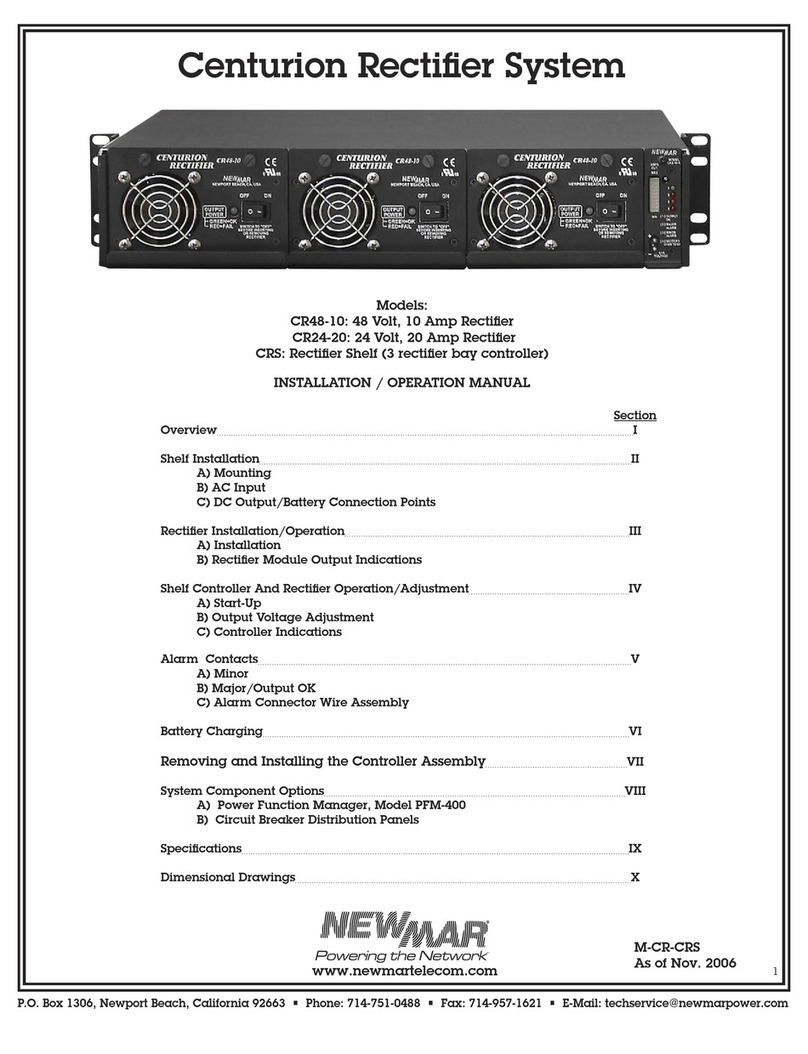
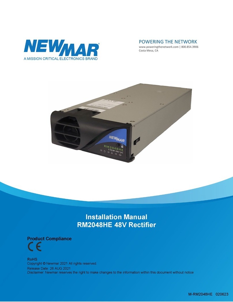
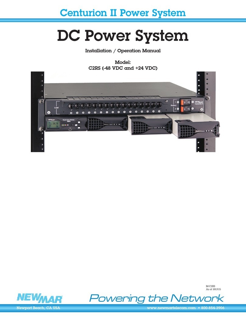
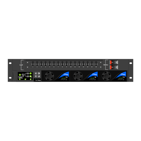
NewMar Commander II Series User manual

NewMar Power System Manual M-CMDRII 063022 Page 1 of 43
Model: COMMANDER II AND COMMANDER II+ Version 1.0
Product Compliance
RoHS
Copyright © NewMar 2021 All rights reserved.
Manual Version 1.1
Release Date: 30 JUL 2022
Disclaimer: NewMar reserves the right to make changes to the information within this document without notice
Commander II Series
Manual
POWERING THE NETWORK
www.poweringthenetwork.com | 800.854.3906
Costa Mesa, CA
The Powerful Difference
M-CMDRII 063022

NewMar Power System Manual M-CMDRII 063022 Page 2 of 43
Model: COMMANDER II AND COMMANDER II+ Version 1.0
Table of Contents
1Admonishments 5
2Safety 5
3Receiving Instructions 6
3.1 Package Inspection 6
3.2 Equipment Inspection 6
3.3 Handing 6
3.4 Identification Labels 6
4Scope 6
5System Overview 7
5.1 Power System 8
5.1.1 Standard Features 8
5.1.2 Additional Features 8
5.1.3 Physical Dimensions and Weight 9
5.2 Energy Manager 9
5.2.1 EM4x-01 Interface 9
5.2.2 Alarms and Status Indicators 10
5.2.3 Energy Manager 3U Touchscreen 10
5.2.4 EM4x Features 10
5.3 Rectifier Modules 11
6Installation 12
6.1 Required Tools 12
6.2 Suitable Racks 12
6.3 Unpacking 13
6.4 Installing the Commander II and II+ System 13
6.5 Rectifier Module Insertion and Removal 16
6.6 Ventilation 17
7Energy Manager Connectivity and the Web UI 17
7.1 Access Levels 17
7.2 Ethernet Port Connection 17
7.3 USB Connection 18
7.4 Energy manager and & IO PCB Alarm Configuration 19
7.4.1 EM4x Alarm Mappings 19
7.4.1.1 EM4x Red LED Urgent Alarm Mapping 20
7.4.1.2 EM4x Yellow LED non-Urgent Alarm Mapping 20
7.4.2 EM4x Main PCB Alarm Mappings 20
7.4.3 EM4x Main PCB Digital Input Alarm Mappings 21
7.4.4 Circuit Breaker Fail Monitoring 21
8LVD Operation 22
9Maintenance 22
9.1 System 22
9.2 EM4x Controller 22
9.3 Rectifiers and Converters 22
9.4 Batteries 23
9.5 Ventilation Maintenance 23
10 Troubleshooting and Servicing 23
10.1 Servicing 23
11 Essential System Setup Parameters 24

NewMar Power System Manual M-CMDRII 063022 Page 3 of 43
Model: COMMANDER II AND COMMANDER II+ Version 1.0
11.1 Systems with Lead Acid Batteries 24
11.1.1 Check the Battery Type 24
11.1.2 Check/Set Float Voltage 24
11.1.3 Set Battery Temperature Compensation 24
11.1.4 Set Battery Capacity 25
11.1.5 Set Batter Current Limit 26
11.1.6 Low Voltage Disconnect Settings 27
11.2 DC System Lead Acid Battery Commissioning Checklist 27
11.3 Systems with Lithium Batteries 31
11.3.1 Check the Battery Type 31
11.3.2 Modular Smart Lithium Battery Selection 31
11.3.3 Check/Set Float Voltage 31
Appendix I Rectifier Fuse and front panel behavior 31
II.A Rectifier Input Fuse Characteristics 31
II.B Rectifier RM3048HE Front Panel Indications 32
II.C DC-DC Convertor Front Panel Indicators 33
Appendix II AC Input Transient Protection 33
II.A Upstream Over-Current Protection 34
II.B Cable Rating 34
II.C Discrimination 34
II.D Surge Suppression Device Protection 34
II.E AC cable installation and surge protection 34
Appendix III Warranty Exclusions and Restrictions 36
III.A Battery Warranty 38
III.B Initiating a Warranty Claim 37
III.C Disclaimer 37
III.D Remark 37
Appendix IV System Schematic 39
Table of Figures
Figure 1: Commander II & Commander II+ 7
Figure 2: Em4x-01 Front Panel Interface 9
Figure 3: Energy Manager 3U Touchscreen 10
Figure 4: RM3048HE Rectifier 11
Figure 5: Removing the Top Cover 13
Figure 6: AC Earth Termination 12
Figure 7: AC Earth Termination 12
Figure 7A: External Earth Termination 12
Figure 8: Connecting the load 12
Figure 8A: Connecting the load 13
Figure 9: Connecting the battery 13
Figure 10: Cable Management 14
Figure 11: Securing the Top Cover 15
Figure 12: Battery Connections 16
Figure 13: Controller Layout 17
Figure 14: RM3048HE Front Panel 18

NewMar Power System Manual M-CMDRII 063022 Page 4 of 43
Model: COMMANDER II AND COMMANDER II+ Version 1.0
Figure 15: Inserting a Rectifier 18
Figure 16: Removing a Rectifier 19
Figure 17: Energy Manager Ethernet Port 20
Figure 18: EMX4x-01 Front Panel micro-USB 20
Figure 19: EM4x Relay Outputs 23
Figure 20: Rectifier Input Fuse Tripping Curves 33
List of Tables
Table 1: Commander II & II+ dimensions and weights 9
Table 2: IO Board 1 Relay Alarm Assignments 23

NewMar Power System Manual M-CMDRII 063022 Page 5 of 43
Model: COMMANDER II AND COMMANDER II+ Version 1.0
1ADMONISHMENTS
The admonishments are the symbols and wording used in this manual to alert readers to specific
dangers and instructions. The meanings of the various admonishments are explained as follows:
Warning = risk to life or personal injury and equipment damage
Caution
= risk of equipment damage.
= risk of electrical shock potentially causing death or injury.
= alert of risk potentially causing death or injury.
= risk of burn injury from hot surfaces
= an alert that must be understood and undertaken.
= instruction of mandatory reading of product manual.
= risk of electrostatic damage to components. Proper
precautions must be taken.
= access for children prohibited.
= restricted access area.
= tip over hazard.
2SAFETY
All installation and maintenance must be carried out by suitably qualified personnel.
For your protection, the product manual should be read and thoroughly understood
before unpacking, installing and using the equipment.
The energy
manager contains static sensitive components that require careful
handling and proper precautions to be t
aken. A grounding strap should be worn.
The equipment is intended only for use in a restricted access area. The equipment is
not suitable for use in locations where children are likely to be present.

NewMar Power System Manual M-CMDRII 063022 Page 6 of 43
Model: COMMANDER II AND COMMANDER II+ Version 1.0
3RECEIVING INSTRUCTIONS
NewMar provides all equipment to the delivering carrier securely packed and in perfect condition. Upon
acceptance of the package from NewMar, the delivering carrier assumes responsibility for its safe arrival.
Once the equipment is received, it is the recipient’s responsibility to document any damage the carrier may
have inflicted, and to file the claim promptly and accurately.
NOTE: the period to make a claim against damage by a transport carrier can be short, a matter of days, and
varies by transport method, the transport contract, and local laws.
3.1 Package Inspection
Examine the shipping crate or carton for any visible damage: punctures, dents and any other signs of possible
internal damage.
Describe any damage or shortage on the receiving documents and have the carrier sign their full name.
3.2 Equipment Inspection
Open the crate or carton and inspect the contents for damages. While unpacking, be careful not to discard
any equipment, parts or manuals. If any damage is detected, call the delivering carrier to determine the
appropriate action. They may require an inspection.
NOTE: Save all the shipping materials for the inspector to see.
After the inspection has been made, if damage has been found, contact NewMar. We will determine if the
equipment should be returned to our plant for repair or if some other method would be more expeditious. If
it is determined that the equipment should be returned to us, ask the delivering carrier to send the packages
back at the delivering carrier’s expense.
If repair is necessary, we will invoice you for the repair so that you may submit the bill to the delivering
carrier with your claim forms.
It is your responsibility to file a claim with the delivering carrier. Failure to properly file a claim for shipping
damages may void warranty service for any physical damages later reported for repair.
3.3 Handling
Handle the equipment with care. Do not drop or lean on front panel or connector. Keep away from moisture.
3.4 Identification Labels
Model number and serial number are clearly marked on all equipment. Please refer to these numbers in all
correspondence with NewMar. Ideally provide a photograph of the product label for reference.
4SCOPE
This manual covers essential information for the installing and commissioning of the NewMar Power System
Commander II (CMDRII) and Commander II+ (CMDRII+) where the significant difference between the systems
is the number of rectifier shelves and the presence of a DC-DC converter shelf, respectively.
NOTE: System set-up for the controller, power modules and other ancillary devices are provided in separate
manuals. Where appropriate these are supplied with the system.
IMPORTANT: this is a generic manual. The Commander II & II+ systems can be configured with a wide range
of options. Should this manual not cover any part of the functionality of your system please contact your
NewMar representative or sales@poweringthenetwork for further information as required.
5SYSTEM OVERVIEW
The Commander II range is designed to allow a customized DC power solution with all the benefits of a
standard “off the shelf” system.
The system is intended to be a complete power system in a box with no connections needed to be made
internally. The system is designed to be extremely simple to install and set up.


NewMar Power System Manual M-CMDRII 063022 Page 7 of 43
Model: COMMANDER II AND COMMANDER II+ Version 1.0
All the AC and DC connections are made from the front of the unit. Alarm connections are also accessible
from the front by opening the hinged front cover.
By adding smart distribution modules, the system can be customized to suit most requirements whilst
maintaining a robust and smart user experience.
NOTE: the system is supplied with the AC and DC earths connected. The standard system output has the DC
Common in the positive side of the circuit (+ve earth system).
5.1 Power System
5.1.1 Standard Features
The base unit is supplied with the following standard options:
•AC Input: Single Phase, 240VAC input
•DC Output: Nominal voltage: 48V DC (contact NewMar for other voltage options)
•EM4x energy manager system controller (fully integrated in the system)
Commander II
Commander II+
EM4x Controller Hinged Front Panel
DC Distribution
•4x 125A Battery MCBs (standard)
•18 x -48V Load MCBs (standard)
•Load & Battery Common Terminals
•500A/50mV Battery Shunt
•500A LVD
•AC Input Terminals (at rear)
Up to 12 x 3kW Rectifiers
•36kW/720A max
4 x 125A Battery Breakers
18 x -48V Load Breakers
9 x 12V or 24V Load Breakers
EM4x Controller Hinged Front Panel
DC Distribution
•4x 125A Battery MCBs (standard)
•18 x -48V Load MCBs (standard)
•Load & Battery Common Terminals
•500A/50mV Battery Shunt
•500A LVD
•AC Input Terminals (at rear)
Up to 8 x 3kW Rectifiers
•24kW/480A max
4 x 125A Battery Breakers
9 x -48V Load Breakers
Up to 8 x 600W DC to DC Converters (12v or 24V)
•4.8kW/320A max
Note: These systems feature multiple
configuration options. Consult the
factory or your Newmar representative
for additional options

NewMar Power System Manual M-CMDRII 063022 Page 8 of 43
Model: COMMANDER II AND COMMANDER II+ Version 1.0
•Battery Low Voltage Disconnect 500A rating
•CTO Configuration:
AC input MCB with surge protection device, type 2
4 x DIN style 27mm battery MCBs
18 x DIN style 18mm load MCBs (max 12 when fitted with 4 battery breakers)
Low voltage battery disconnect (LVBD) and low voltage load disconnect (LVLD)
5.1.2 Current Capacities
•Commander II system capacity is up to 720A with a maximum of 12x RM3048HE power modules. The
Commander II+ system capacity is up to 480A with a maximum of 8x RM3048HE and a maximum of 8
DC-DC converters with 12V or 24V output at 40A and 43A, respectively.
5.1.3 Additional Features
•AC input MCB with surge protection device, type 2
•I/O board
•AC monitoring including voltage, frequency and current
•Fan control
•Battery control monitoring
•Battery fuse fail
•Site monitoring
5.1.4 Physical Dimensions and Weights
Table 1: Commander II & II+ dimensions and weights
Model
Commander II
Commander II+
Depth (Total)
380mm
380mm
Width (Total)
483mm (19”
mount)
483mm (19”
mount)
Height
267mm (6U)
311mm 7U
Weight without rectifiers
22.7kg
22.7kg
Weight with max.
rectifiers
38.3kg
46.7kg
5.2 Energy Manager
5.2.1 EM4x-01 Interface
Touchscreen
Status LEDs
Micro-USB
Figure 2: EM4x-01 Front Panel Interface

NewMar Power System Manual M-CMDRII 063022 Page 9 of 43
Model: COMMANDER II AND COMMANDER II+ Version 1.0
IMPORTANT: all system and module documentation can be accessed via the micro-USB port on the front
panel of the energy manager.
5.2.2 Alarms and Status Indicators
•Status LEDs:
◦Red LED Urgent alarm state.
◦Orange LED Non-Urgent alarm
◦Green LED DC power is connected to the unit; Energy Manager is functioning
NOTE:The LED mapping can be user modified.
•The energy manager is fitted with an audible buzzer which can be configured to alert to any alarm
depending on the alarm mapping.
NOTE:To disable the buzzer when active, tap the screen.
•Micro-USB Connector: can independently power the EM4x and provides access to the Web UI
5.2.3 Energy Manager Touchscreen
*NOTE: when there are multiple alarms raised the Active Alarm display cycles through the list. The complete
list can be viewed by tapping Alarms.
Tap the touchscreen to navigate through the menus.
NOTE: the EM4x-01 has the option to PIN lock function change through the front screen interface. See the
EM4x manual for details.
5.2.4 EM4x Features
The EM4x microcontroller-based DC system energy manager provides the control and monitoring functions
for all NewMar Energy’s power systems. With an appropriate communications connection third party lithium
battery can also be managed.
The EM4x monitors all power system conditions including DC voltage, rectifier current, battery current, battery
temperature, distribution failure and battery pack status. It has an in-built web-based configurator allowing
setup of system parameters, monitoring, updating and download of logs using a web browser as well as a
front panel interface through which key parameters are also configurable. Visual notification of alarm
conditions is given by LEDs and a display mounted on the front of the EM4x, with remote notification being
enabled by relay contacts, RS232 or TCP/IP (using SNMP).
The EM4x utilizes a USB communications port which allows for local monitoring of system operations as well
as pre-commission and power down configuration of the Web UI.
The EM4x also incorporates the following features:
• Support for NewMar’s battery modules with optimized battery backup functions
• Support for third-party external batteries, both lead-acid and lithium based
• Support for AC-DC rectifiers (24V and 48V Outputs)
• Support for DC-DC converters (12V, 24V and 48V Outputs)
Information
Alarms
Settings
Batteries
State of Charge (SoC)
Load
Rectifiers
Renewables
Estimated Time Remaining (ETR)
Active Alarm*
Bus Voltage
Figure 3: Energy Manager Touchscreen

NewMar Power System Manual M-CMDRII 063022 Page 10 of 43
Model: COMMANDER II AND COMMANDER II+ Version 1.0
• Control of up to two low voltage disconnects (magnetically latched contactors) per I/O board*
• Network connectivity (web access)
• System voltage metering for primary system DC supply. (e.g., 48V primary DC output)
• Load, battery and rectifier current metering and alarms
• Active rectifier and converter current share
• Automatic system voltage control
• Effectively unlimited alarm thresholds as standard, for use with multiple DC outputs
• Advanced monitoring, display and logging of battery packs, and system performance data
• Advanced hybrid site control and monitoring with patented anti-stall feature for generators.
• Phase balance controls for multi-phase and single-phase AC input management
• Sophisticated programmable logic control
• For lead-acid external batteries -
◦Battery and room temperature metering and alarms (when fitted with optional temperature
sensors)
◦Optional complete or battery mid-point monitoring (when fitted with optional battery monitor
cards)
◦Temperature compensation of float voltage (when fitted with optional temperature sensors)
◦Manual equalize charging to prolong the life of the batteries
◦Periodic equalize charging to prolong the life of the batteries
◦Fast charging after battery discharge
◦Battery capacity remaining indication
◦Battery testing facility
◦Battery current limit
• Six user defined General Purpose Inputs (“GPIPs”) which can be software configured as either digital or
analogue inputs* (up to 10 may be made available under special circumstances)
• Six relay outputs*
• I/O Expansion card capability*
• Expanded serial and CAN communications – up to 5 I/O boards can be connected to a single EM4x *
Note: the addition of an I/O Expansion card to the EM4x allows for analogue inputs and increases the
number of digital inputs and relay outputs available. The controller allows for these new
inputs/outputs to be logically combined allowing a degree of control of peripheral functions. E.g., a
temperature triggered room fan or humidity detection.
5.3 Rectifier Modules
The RM3048HE is a telecommunications grade rectifier with the following features:
•High efficiency
•Hot pluggable
•Forced air cooled
•Thermally protected
Figure 4: RM3048HE Rectifier
Fan Cooled
Unlock Button
Status LEDs

NewMar Power System Manual M-CMDRII 063022 Page 11 of 43
Model: COMMANDER II AND COMMANDER II+ Version 1.0
•Power factor corrected
•Wide input AC voltage
•Constant power output limit
•Input/Output voltage and current protected
•Active load sharing
•Serial alarm and control interface
•Microprocessor controlled
There are 3 LED indicators on the front panel which indicate the operational state of the rectifier:
Red LED
Urgent alarm state.
Yellow LED
Non-Urgent alarm.
Green LED
DC power is connected to the unit.
This LED flashes during power save mode.
6INSTALLATION
WARNING All upstream AC, Load and Battery breakers must be switched OFF prior to
installation. The system must be completely de-powered.
All circuit breakers in a NewMar power system must be in their OFF position prior to installation.
WARNING Use extreme care when fitting batteries & their connections. Remove all
conductive materials from yourself such as watches, jewelry and rings prior to
commencing the installation. DO NOT short terminals when working on them.
WARNING Use extreme care when fitting solar panel connections. DO NOT short
terminals when working on them.
CAUTION Avoid resting cables on sharp edges (cold-creep)
The energy manager contains static sensitive components that require careful
handling and proper precautions to be taken. A grounding strap should be worn.
6.1 Required Tools
Insulated M6 or ¼”, M8 or 5/16” pozi Screwdriver, insulated 0.6mm x 2.5mm diameter flat head screwdriver,
Insulated M10 or 3/8” bolt wrench/ratchet set and as required depending on set up available.
6.2 Suitable Racks

NewMar Power System Manual M-CMDRII 063022 Page 12 of 43
Model: COMMANDER II AND COMMANDER II+ Version 1.0
Recommended rack size is 19” and minimum 600mm deep.
6.3 Unpacking
Upon unpacking, check that the unit is not damaged, and that you have the required number of modules and
blank panels (if and as appropriate for your system).
NOTE: Do not fit rectifier modules until the Commander power system has been installed into the rack.
6.4 Installing the Commander System
STEP 1: Remove the Drip cover from the
system by removing the 3 thumbscrews.
Retain for reuse.
STEP 2: Mount the system in the cabinet or
rack as appropriate.
STEP 2: Connect the AC supply.
Terminate the cables to the input circuit breakers and
the terminal blocks for Earth and phase to phase (or L1
to L2) (see AC wiring options for Commander II series).
NOTE:the AC terminals accept up to 1/0 AWG/55mm2
cables.
NOTE: the AC earth terminal is connected directly to the
system chassis.
NOTE: AC and DC EARTHING - This system has a built-
in AC to DC earth connection. No extra AC to DC earth
link cable is required. However, an additional
grounding point has been provided to ensure the unit
meets any additional requirements. Removing this link
will void the warranty. Please check with NewMar
should this link be required to be removed.
STEP 4: Connect the Load.
Figure 7A: External Earth Termination
Figure 6: AC Termination
Figure 7: AC Earth Termination
Chassis Earth
AC
Figure 5 Top Cover

NewMar Power System Manual M-CMDRII 063022 Page 13 of 43
Model: COMMANDER II AND COMMANDER II+ Version 1.0
Load Common (+ve): all load common connections are made to the connectors
placed behind the circuit breakers. 2 sizes of common terminals are available, up to
4AWG/25mm2and 2 AWG/35mm2.
NOTE: cables smaller than 6mm2(10 AWG) should be terminated to the
4AWG/25mm2connectors to make sure of adequate clamping force.
Load Live (-ve): Load Live cables are connected directly to the terminals at the top
of the circuit breakers. Load breaker terminals are sized to accept cables up to
4AWG/25mm2.
Load distributions that include a secondary load LVD (LLVD) are split into 2
sections to allow prioritization of the connected loads. Non-priority loads are
removed from circuit prior to the primary battery LVD operation to extend the time
of operation of the priority loads. Load distributions in systems without the
secondary LLVD are all removed from circuit together at the battery LVD
disconnect point.
Please refer to the specification of the system to determine which breakers are
priority and non-priority loads (if optioned).
NOTE: make sure all incoming cables have adequate strain relief.
STEP 5: Connect the Batteries
Battery Common (+ve): All Battery Common connections are made to the busbar
located placed behind the Circuit breakers. Accepts cables up to 1/0 AWG/55mm2.
Battery Live (-ve): Battery Live cables are connected directly to the terminals at the
top of the circuit breakers. Battery breaker terminals are sized to accept cables up
to 1/0 AWG/55mm2.
NOTE:make sure all incoming cables have adequate strain relief.
Figure 8 Connecting the load
Figure 8A Connecting the load
Figure 9 Connecting the
battery

NewMar Power System Manual M-CMDRII 063022 Page 14 of 43
Model: COMMANDER II AND COMMANDER II+ Version 1.0
STEP 6: Secure the cables using the Cable Management System
Attached to the top of the unit is the cable management system. The system will accommodate cables up to 2
AWG/35mm2. Start by inserting the cable tiedown into the slotted aluminum rail. Rotate clockwise to lock the
cable tiedown into place. For cables up to 6AWG/16mm2, place the cables across the cable tiedown and secure
with a cable tie. For cables up to 2 AWG/35mm2, place the cables on either side of the cable tiedown and
secure with a cable tie.
STEP 7: Affix the Battery Temperature Sensor
Uncoil and affix the battery temperature sensor in the center of the middle battery string.
NOTE:The purpose of battery temperature sensor is to monitor the ambient temperature of the batteries over
long periods of time and adjust the rectifier output (float) voltage accordingly.
NOTE: Refer to the specifications supplied by the battery vendor for battery operational temperature
requirements.
STEP 8: Affix the Ambient Temperature Sensor
Uncoil and affix the ambient temperature sensor in a position that will give an indication of average
cabinet/room temperature.
NOTE: refer to the EM4x energy manager, RM3048HE Rectifier
STEP 9: Terminate External I/O Connections
Terminate external I/O connections if any to the Energy manager. Refer to the EM4X Relay output and digital
input sections for mappings in the EM4x Manual. The Monitor layout is as shown in Figure 12.
NOTE: The inputs are normally activated by connecting system positive (usually system common) to the input.
NOTE: Route and secure Alarm Extension Loom away from AC and DC cables
NOTE: For full EM4x functionality and operation information, refer to the EM4x Manual.
Note: For cables up to 2 AWG/35mm2,feed the
cable tie between the aluminum rail and the cable
tie down.
Note: Alternate and stagger the cable tie downs to maximize the available space.
Figure 10 Cable Management

NewMar Power System Manual M-CMDRII 063022 Page 15 of 43
Model: COMMANDER II AND COMMANDER II+ Version 1.0
STEP 10: Secure the Drip Cover
Secure the drip cover to the top of the unit with the thumbscrews
Figure 11 Securing the drip cover

NewMar Power System Manual M-CMDRII 063022 Page 16 of 43
Model: COMMANDER II AND COMMANDER II+ Version 1.0
Figure 12: Controller Layout
6.5 Rectifier Module Insertion and Removal
Rectifier modules are shipped separately. They must be
plugged in to the system prior to power-up.
The rectifier modules are designed for “hot plug-and-play”. It is safe to insert and remove modules at any
time, even when the system is loaded.
The rectifier modules are self-addressing, meaning that no setup
is required for the EM4x controller to determine rectifier
addressing.
IMPORTANT: if a rectifier is removed from the system and then
plugged into another rectifier slot, you must wait for the red LED
to extinguish (this clears the address setting in the EPROM).
When inserting the module, ensure that it is pressed hard into
the system. The locking button should click. See Figure 14.
To remove the module, press the locking button while pulling on
the “handle” that is integrated into the front panel. See Figure 15.
Check that any blank rectifier slots have the rectifier blank panel
inserted to prevent air back-flow.
Locking Button
Integrated Handle
Figure 13: RM3048HE Front Panel
Figure 14: Inserting a Rectifier
Pull out the rectifier
Press the locking button
Figure 15: Removing a Rectifier

NewMar Power System Manual M-CMDRII 063022 Page 17 of 43
Model: COMMANDER II AND COMMANDER II+ Version 1.0
6.6 Ventilation
The performance of the rectifier or other power modules can be limited if the ventilation is restricted. The
rectifier is cooled by drawing air into the front of the unit with a single fan. This air passes through the rectifier
cooling the electronics and exiting the rectifier at the rear. For efficient airflow:
•Check the air at the front of the rack is at ambient temperature and not being heated by other
equipment.
•That the rectifier shelf has at least 3“/75mm clear horizontal space behind it. This space must be clear
of cables and any other components that may restrict air movement.
NOTE: if multiple rectifier shelves are installed then there should be at least 3”/75mm clear horizontal
space per shelf.
•Check the free space in the rack continues vertically to the exhaust point at the top of the rack,
without impediment.
•Check the hot exhaust air does not re-circulate to the front of the rack as this will be drawn into the
rectifiers again, in effect raising the apparent ambient temperature.
•Check the operating environment is low dust and fiber.
Pay particular attention to the quality of rectifier air intake. Insects, sand, and other
extraneous matter ingress seriously impacts the performance of the rectifiers.
7ENERGY MANAGER CONNECTIVITY AND THE WEB UI
The energy manager is configured via a web browser-based user interface (Web UI).
There are two methods to access the Web UI:
1. Ethernet connection from the J305 ethernet connector
2. Front panel micro-USB local connection
7.1 Access Levels
There are 3 access levels for the Energy Manager Web UI:
enaguest : can only view status of system
enabasic : reduced privilege, can view settings and system status
enaadvanced : this user has normal full control access of the system
The default password for all levels = ena123
7.2 Ethernet Port Connection
The energy manager contains static sensitive components that require
careful handling and proper precautions to be taken – an electrostatic discharge
protection device must be worn.
Figure 16: Energy Manager Ethernet Port

NewMar Power System Manual M-CMDRII 063022 Page 18 of 43
Model: COMMANDER II AND COMMANDER II+ Version 1.0
1. Connect the communicating device to the J305 Ethernet port inside the energy manager.
2. Open an internet browser such as Edge, Chrome, Firefox or similar on the device.
3. Enter the Ethernet default IP address into the internet browser.
NOTE: the energy manager IP address can be located from the front panel LCD menu under:
Settings>Networking>Ethernet.
4. The energy manager log in page appears.
5. Enter the user name and password. See 7.1 Access Levels.
7.3 USB Connection
Figure 17: 3U EM4x-01 Front Panel micro-USB
1. Connect the communicating device to the micro-USB port on the front of the energy manager. See
Figure 17.
A driver installation prompt appears.
2. Double-click the appropriate USB driver (32bit or 64 bit).
3. Follow the installation wizard instructions to install the driver.
4. Open an internet browser such as Edge, Chrome, Firefox or similar.
5. Enter the USB default IP address into the internet browser: 172.31.250.1
6. The energy manager log in page appears.
6. Enter the username and password. See 7.1 Access Levels.
Note: USB connection to the energy manager is possible without AC, battery or other external power supply.
The EM4x operates drawing power through the USB port. However, USB supply does not power the IO Board.
Ethernet Port
Micro-USB

NewMar Power System Manual M-CMDRII 063022 Page 19 of 43
Model: COMMANDER II AND COMMANDER II+ Version 1.0
In this scenario there is a set of alarms that display depending on the system configuration relating to the
nonoperation of the IO board.
For example:
For information on the use of the energy manager Web UI please refer to the Energy Manager Installation and
Operation Manual.
7.4 Energy manager & IO PCB Alarm Output Configuration
For full EM4x functionality and operation information, refer to the EM4x Installation and Operation Manual.
7.4.1 EM4x LED Alarm Mappings
Refer to the Alarm Configuration>Alarm Configuration page of the Web UI to see the priority setting of each
alarm.
Refer to the Relay/Output page Configure Relay section of the Web UI to understand the how the Alarm
Configuration is mapped to the EM4x LEDs.
7.4.1.2 EM4x Yellow LED non-Urgent Alarm Mapping
7.4.1.1
EM4x Red LED Urgent Alarm Mapping
(
For reference only. Actual system alarm mapping may vary)

NewMar Power System Manual M-CMDRII 063022 Page 20 of 43
Model: COMMANDER II AND COMMANDER II+ Version 1.0
7.4.2 EM4x Main PCB Alarm Mappings
Alarms can be mapped to any of the voltage free output relays fitted to the EM4x. Output states of either
Normally Open or Normally Closed can be selected (NO and NC states are for the de-energized relay). A
jumper is fitted to nominate the required output state, ensure the jumper is placed in the correct configuration
for installation requirements.
If an alarm is programmed for the relay to be normally energized (such as a low voltage alarm where loss of
power will put the alarm into its “active” state), then be sure to connect the remote wiring appropriately.
Table 2 lists alarm assignment for the EM4x controller as matches the relay outputs shown in Figure 18.
Figure 18: EM4x Relay Outputs
Table 2: IO Board 1 Relay Alarm Assignments
Relay
Output
Relay Label
(In NewMar Config.)
Alarms Mapped to Relay/Output
(All multiple states “OR-ed”)
Relay 1
CPU Fail
Relay 2
Non-Critical Alarms
Orange LED
(
For reference only. Actual system alarm mapping may vary)
Relay Outputs 1
-
6
This manual suits for next models
1
Table of contents
Other NewMar Power Supply manuals

NewMar
NewMar RM2048HE User manual

NewMar
NewMar POWER-PAC User manual

NewMar
NewMar EP 12-10 User manual

NewMar
NewMar Phase Three PT-CE Series User manual

NewMar
NewMar MDP-25 User manual

NewMar
NewMar power-pac User manual

NewMar
NewMar Centurion II User manual

NewMar
NewMar PM-12-40 User manual

NewMar
NewMar PM-24-80 User manual

NewMar
NewMar Centurion III C3RS-48-124 User manual