Vertiv NetSure 584130100 User manual

NetSure™
Inverter System
User Manual
Specification Number: 584130100

Vertiv™ NetSure™ Inverter System User Manual
The information contained in this document is subject to change without
notice and may not be suitable for all applications. While every precaution has
been taken to ensure the accuracy and completeness of this document, Vertiv
assumes no responsibility and disclaims all liability for damages resulting from
use of this information or for any errors or omissions. Refer to other local
practices or building codes as applicable for the correct methods, tools, and
materials to be used in performing procedures not specifically described in
this document.
The products covered by this instruction manual are manufactured and/or
sold by Vertiv. This document is the property of Vertiv and contains
confidential and proprietary information owned by Vertiv. Any copying, use or
disclosure of it without the written permission of Vertiv is strictly prohibited.
Names of companies and products are trademarks or registered trademarks of
the respective companies. Any questions regarding usage of trademark
names should be directed to the original manufacturer.
Technical Support Site
If you encounter any installation or operational issues with your product, check the pertinent section of this
manual to see if the issue can be resolved by following outlined procedures.
Visit https://www.vertiv.com/en-us/support/ for additional assistance.

Vertiv™ NetSure™ Inverter System User Manual
Proprietary and Confidential © 2023 Vertiv Group Corp.
iii
TABLE OF CONTENTS
Admonishments Used in this Document.............................................................................................................................iv
Important Safety Instructions..................................................................................................................................................v
1Customer Documentation Package..................................................................................................................................1
2System Description ................................................................................................................................................................1
3Operating Procedures..........................................................................................................................................................3
3.1 Controller and Inverters..........................................................................................................................................................................................................................................3
3.2 EPO (Emergency Power Off) Function.....................................................................................................................................................................................................3
3.3 Local Controls and Indicators ...........................................................................................................................................................................................................................3
3.3.1 Controller and inverters....................................................................................................................................................................................................................3
3.3.2 AC load distribution disconnect circuit breakers.....................................................................................................................................................4
4Maintenance.............................................................................................................................................................................5
4.1 System Maintenance Procedures..................................................................................................................................................................................................................5
4.2 Adding an Inverter Module ..................................................................................................................................................................................................................................5
5Troubleshooting and Repair ..............................................................................................................................................5
5.1 Contact Information....................................................................................................................................................................................................................................................5
5.2 Controller and Inverters..........................................................................................................................................................................................................................................5
5.3 Controller Configuration.........................................................................................................................................................................................................................................5
5.4 System Troubleshooting Information ........................................................................................................................................................................................................5
5.5 Replacement Information......................................................................................................................................................................................................................................6
5.6 Replacement Procedures......................................................................................................................................................................................................................................6
5.6.1 Replacing an inverter module.....................................................................................................................................................................................................6
5.6.2 Replacing the NCU controller.....................................................................................................................................................................................................6
5.6.3 Circuit card replacement procedures..................................................................................................................................................................................6

Vertiv™ NetSure™ Inverter System User Manual
Proprietary and Confidential © 2023 Vertiv Group Corp.
iv
Admonishments Used in this Document
DANGER
! Warns of a hazard the reader will be exposed to that will likely result
in death or serious injury if not avoided. (ANSI, OSHA)
WARNING
! Warns of a potential hazard the reader may be exposed to that could
result in
death or serious injury if not avoided. This admonition is not used for situations that pose a
risk only to equipment, software, data, or service. (ANSI)
CAUTION
! Warns of a potential hazard the reader may be exposed to that could
result in minor or moderate injury if not avoided. (ANSI, OSHA) This admonition is not
used for situations that pose a risk only to equipment, data, or service, even if such use
appears to be permitted in some of the applicable standards. (OSHA)
ALERT
!Alerts the reader to an action that must be avoided in order to protect
equipment, software, data, or service. (ISO)
ALERT
! Alerts the reader to an action that must be performed in order to prevent
equipment damage, software corruption, data loss, or service interruption. (ISO)
FIRE SAFETY
! Informs the reader of fire safety information, reminders, precautions,
or policies, or of the locations of fire
-fighting and fire-safety equipment. (ISO)
SAFETY
! Informs the reader of general safety information, reminders, precautions, or
policies not related to a particular source of hazard or to fire safety. (ISO, ANSI, OSHA)

Vertiv™ NetSure™ Inverter System User Manual
Proprietary and Confidential © 2023 Vertiv Group Corp.
v
Important Safety Instructions
Safety Admonishments Definitions
Definitions of the safety admonishments used in this document are listed under “Admonishments Used in this Document” on page iv.
Safety and Regulatory Statements
Refer to Section 4154 (provided with your customer documentation) for Safety and Regulatory Statements.
Déclarations de Sécurité et de Réglementation
Reportez-vous à la Section 4154 (fourni avec les documents de votre client) pour les déclarations de sécurité et de réglementation.

Vertiv™ NetSure™ Inverter System User Manual
Proprietary and Confidential © 2023 Vertiv Group Corp.
vi
This page intentionally left blank.

Vertiv™ NetSure™ Inverter System User Manual
Proprietary and Confidential © 2023 Vertiv Group Corp.
1
1Customer Documentation Package
This document (UM584130100) provides User Instructions for the Vertiv™ NetSure™ Inverter System: Spec. No. 584130100.
The complete Customer Documentation Package consists of…
System Installation Manual
•System Installation Instructions: IM584130100
Controller User Manual
•NCU Controller User Instructions: UM1M830BNA
USB Drive with All Customer Documentation
•System Installation Instructions: IM584130100
•System User Instructions: UM584130100
•System “System Application Guide”: SAG584130100
•NCU Controller User Instructions: UM1M830BNA
•Inverter Instructions: UM1I1201000
•Engineering Drawings
-SD584130100
-T584130100
•Also provided on the USB drive are the controller configuration files loaded into the controller as shipped and a controller
configuration drawing (C-drawing).
For factory settings of all configurable controller parameters, refer to the controller configuration drawing (C-drawing) supplied with
your system.
2System Description
120 VAC @ up to 24 kVA Inverter System
The Vertiv™ NetSure™ Inverter System is a complete inverter system containing inverters, intelligent control, metering, monitoring,
and distribution.
The inverter system can be set to operate in one of three input power modes: AC Input Power Mode, DC Input Power Mode, and DC
Input Only Power Mode.
NOTE! List 05 and 05E have no AC input and can only operate in 'DC Input Only Power Mode'.
•In the AC Input Power Mode, each inverter module operates with the commercial AC input to supply 120 VAC power to the
loads. In the event commercial AC power fails or becomes abnormal, the inverter modules immediately transfer operation
with the 48 VDC nominal input to power to the inverters.
•In the DC Input Power Mode, each inverter module operates with the 48 VDC nominal input to supply 120 VAC power to the
loads. In the event DC power fails or becomes abnormal or an inverter module fails, the inverter module immediately
transfers operation with the commercial 120 VAC input to power to the inverters.

Vertiv™ NetSure™ Inverter System User Manual
Proprietary and Confidential © 2023 Vertiv Group Corp.
2
•In the DC Input Only Power Mode, each inverter module operates with the 48 VDC nominal input to supply 120 VAC power to
the loads.In the event DC power fails or becomes abnormal or an inverter module fails, the inverter module shuts off.
The inverter system contains an EPO (Emergency Power Off) function. Connection points for a normally closed external EPO switch
are provided on the customer interface board. If an external EPO switch is wired to the customer interface board, activating the
switch to open the circuit activates the EPO function. The EPO function shuts down and locks out the inverters. When the EPO
switch is returned to normal (closed loop), the inverters remain off. The inverters will restart when the AC and DC power inputs are
removed and restored after 30 seconds or more (until the LEDs on the modules extinguish) (depending on the synchronizing time
with the system). (Note that there is an EPO shorting link factory installed that can be replaced with a customer provided switch.)
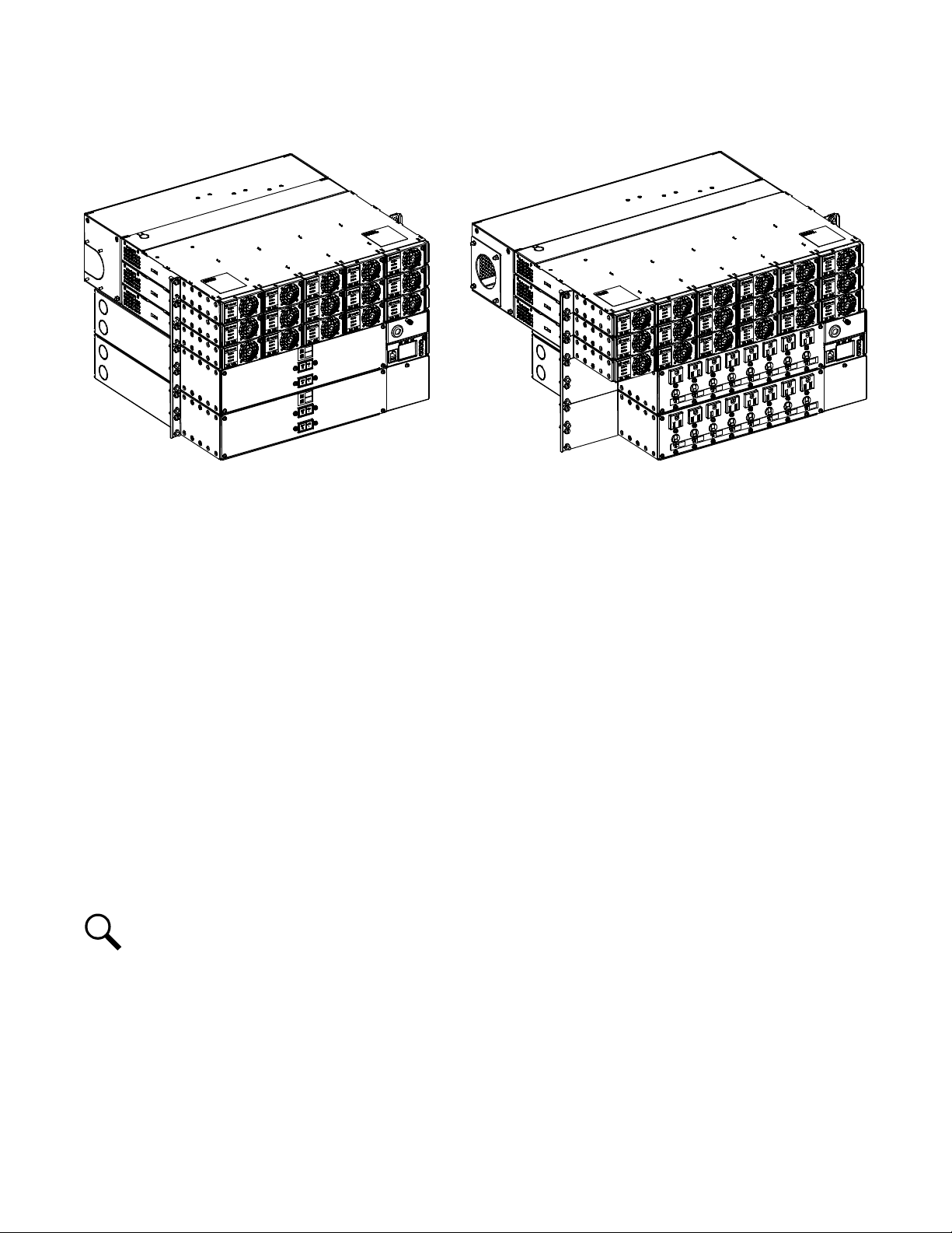
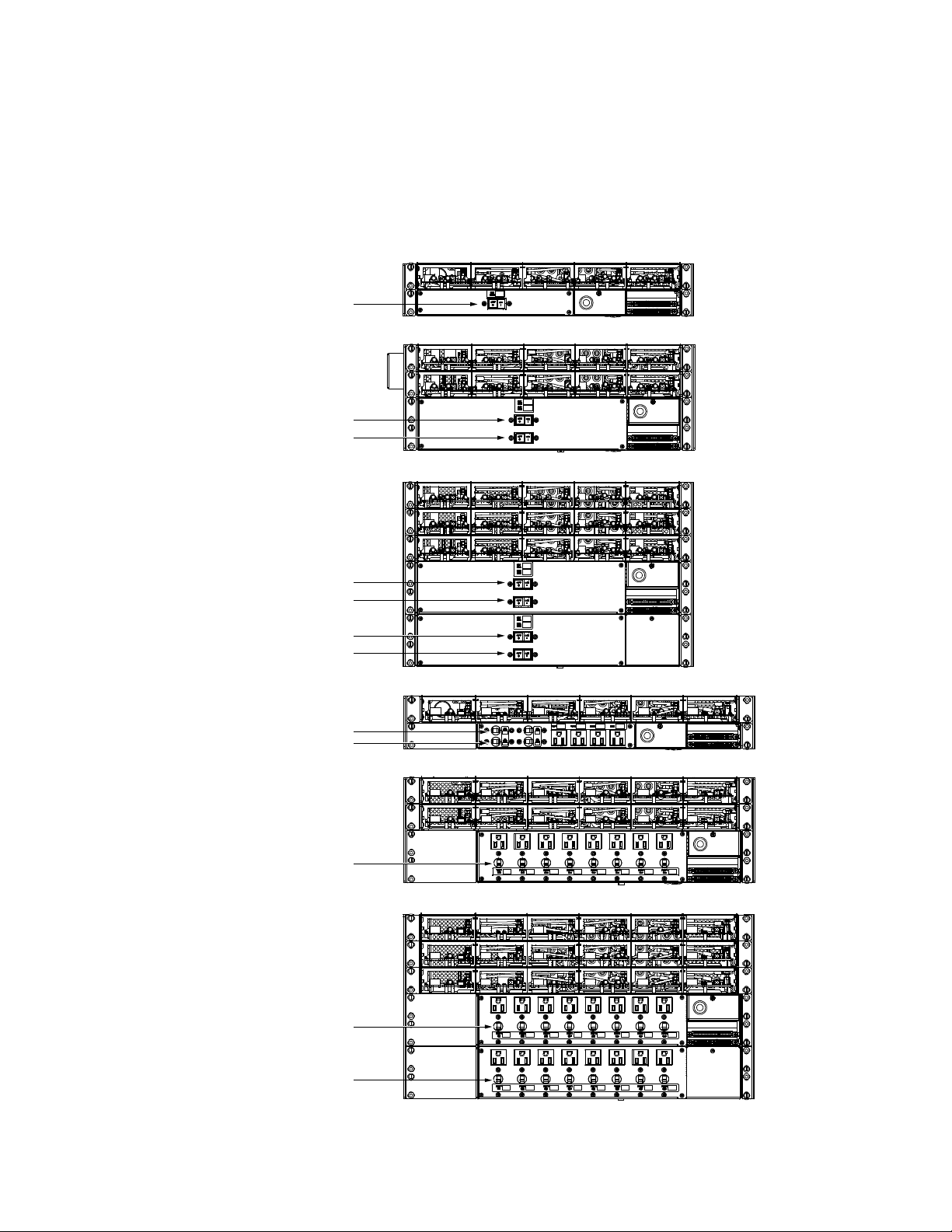
This inverter system consists of the following components. These components are factory packaged to provide the inverter system
configurations listed in Table 2.1. See Figure 2.1 for an overview illustration. Note the ratings are not only determined by the maximum
number of inverters the system can be provided with, but also the rating of the AC distribution panel. The overall system rating
cannot exceed the AC distribution panel rating.
Inverter Module Mounting Shelf(s)
The inverter system consists of one or more inverter module mounting shelves, depending on power rating. The inverter module
mounting shelves house the inverter modules.
Inverter Modules
The inverter system utilizes 1 kVA/1 kW inverter modules (1 kVA at 40 °C and 0.5 kVA at 65 °C), supplying 120 VAC power from a
commercial AC power source or from a 48 VDC nominal input. Refer to the Inverter Instructions (UM1I1201000) for more information.
AC Load Distribution Shelf(s)
The inverter system consists of one or more AC load distribution shelves, depending on power rating. A choice of a bulk output AC
load distribution shelf or a NEMA output AC load distribution shelf is provided.
NCU (NetSure™ Control Unit) Controller
The controller provides inverter control, metering functions, monitoring functions, and local/remote alarm functions. The controller
also provides data acquisition and system alarm management. The controller contains a color LCD display and keypad for local
access. The controller provides an Ethernet port and comes with comprehensive webpages for remote access. The controller has
SNMP capability for remote system management. The controller supports software upgrade via its USB port. Refer to the NCU
Controller Instructions (UM1M830BNA) for more information.
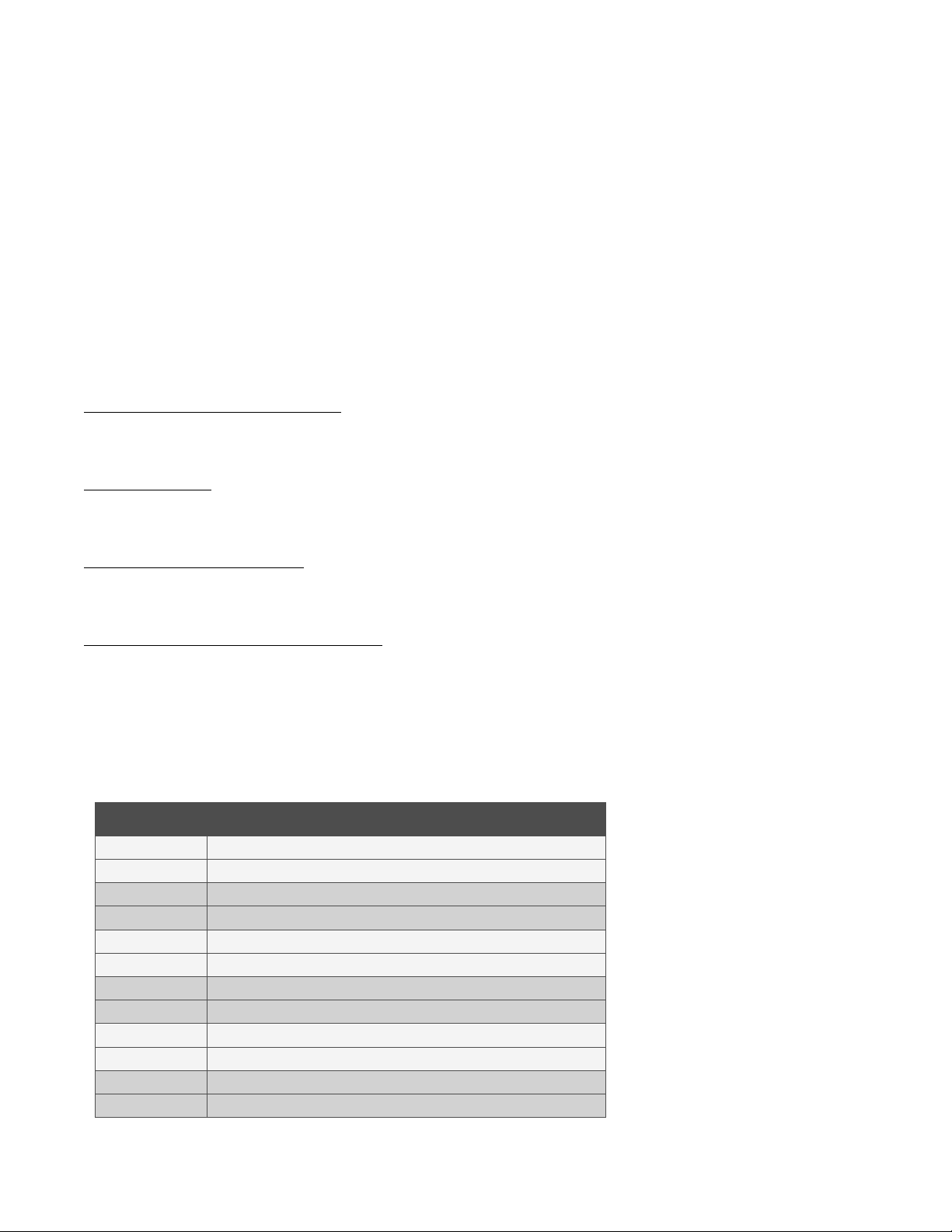
Table 2.1 Inverter System Configurations
List Number Configuration
584130100 List 01 19”, 5 kVA maximum, Bulk Output Shelf
584130100 List 01E 19”, 6 kVA maximum, Bulk Output Shelf
584130100 List 02 23”, 6 kVA maximum (5.76 kVA per NEC breaker de-rating), NEMA Output Shelf
584130100 List 02E 23”, 6 kVA maximum (5.76 kVA per NEC breaker de-rating), NEMA Output Shelf
584130100 List 03 19”, 10 kVA maximum, Bulk Output Shelf
584130100 List 03E 19”, 12 kVA maximum, Bulk Output Shelf
584130100 List 04 23”, 12 kVA maximum (11.5 kVA per NEC breaker de-rating), NEMA Output Shelf
584130100 List 04E 23”, 12 kVA maximum (11.5 kVA per NEC breaker de-rating), NEMA Output Shelf
584130100 List 05 19”, 15 kVA maximum, Bulk Output Shelf - DC INPUT ONLY
584130100 List 05E 19”, 20 kVA maximum, Bulk Output Shelf - DC INPUT ONLY
584130100 List 06 23”, 18 kVA maximum (18 kVA per NEC breaker de-rating), NEMA Output Shelf
584130100 List 06E 23”, 24 kVA maximum (23 kVA per NEC breaker de-rating), NEMA Output Shelf

Vertiv™ NetSure™ Inverter System User Manual
Proprietary and Confidential © 2023 Vertiv Group Corp.
3
Figure 2.1 Inverter System Overview Illustration
3Operating Procedures
3.1 Controller and Inverters
For operation instructions on these units, refer to the following documents.
•NCU Controller Instructions (UM1M830BNA)
•Inverter Instructions (UM1I1201000)
3.2 EPO (Emergency Power Off) Function
The inverter system contains an EPO (Emergency Power Off) function. Connection points for a normally closed external EPO switch
are provided on the customer interface board. If an external EPO switch is wired to the customer interface board, activating the
switch to open the circuit activates the EPO function. The EPO function shuts down and locks out the inverters. When the EPO
switch is returned to normal (closed loop), the inverters remain off. The inverters will restart when the AC and DC power inputs are
removed and restored after 30 seconds or more (until the LEDs on the modules extinguish) (depending on the synchronizing time
with the system). (Note that there is an EPO shorting link factory installed that can be replaced with a customer provided switch.)
NOTE! If a customer-furnished method to disconnect the AC and DC power inputs to the system is not provided, the
inverters will stay locked OFF until the input power is recycled. If the EPO switch is returned to normal (closed loop) without
recycling the input power, the inverters will remain off and have a local alarm visible on the module. The EPO alarm from the
controller will extinguish. The controller will not issue an alarm for this condition.
3.3 Local Controls and Indicators
3.3.1 Controller and inverters
Refer to the controller and inverter instructions for descriptions of the local controls and indicators located on these units.
15 kVA Bulk Output System
(584130100 List 05)
18 kVA NEMA Output System
(584130100 List 06)

Vertiv™ NetSure™ Inverter System User Manual
Proprietary and Confidential © 2023 Vertiv Group Corp.
4
3.3.2 AC load distribution disconnect circuit breakers
The distribution shelf(s) contains front panel AC load distribution disconnect circuit breakers. For the NEMA output AC load
distribution shelf, there is a circuit breaker for each outlet. For the bulk output AC load distribution shelf, there is a circuit breaker for
each bulk output. See Figure 3.1.
Figure 3.1 AC Load Distribution Disconnect Circuit Breakers
Front
Front
Front
Front
Front
Front
584130100 List 03 (584130100 List 03E Similar)
584130100 List 01 (584130100 List 01E Similar)
584130100 List 05 (584130100 List 05E Similar)
584130100 List 02 (584130100 List 02E Similar)
584130100 List 04 (584130100 List 04E Similar)
584130100 List 06 (584130100 List 06E Similar)
Bulk Output Load Disconnect
70 A Circuit Breaker
Bulk Output Load Disconnect
70 A Circuit Breaker
Bulk Output Load Disconnect
70 A Circuit Breaker
Bulk Output Load Disconnect
70 A Circuit Breaker
Bulk Output Load Disconnect
70 A Circuit Breaker
Bulk Output Load Disconnect
70 A Circuit Breaker
Bulk Output Load Disconnect
70 A Circuit Breaker
NEMA Output Load Disconnect
15 A Circuit Breaker (each)
NEMA Output Load Disconnect
15 A Circuit Breaker (each)
NEMA Output Load Disconnect
15 A Circuit Breaker (each)
NEMA Output Load Disconnect
15 A Circuit Breaker (each)
NEMA Output Load Disconnect
15 A Circuit Breaker (each)

Vertiv™ NetSure™ Inverter System User Manual
Proprietary and Confidential © 2023 Vertiv Group Corp.
5
4Maintenance
4.1 System Maintenance Procedures
It is recommended to perform the maintenance procedures listed in Table 4.1 every 6-months to ensure continual system operation.
Table 4.1 Maintenance Procedures to be Performed at 6-Month Intervals
Procedure Referenced In
Check ventilation openings for obstructions
such as dust, papers, manuals, etc. --
Inspect and tighten all installer's connections. IM584130100,
“Making Electrical Connections” section.
4.2 Adding an Inverter Module
To increase system current capacity, an inverter module can easily be added to an existing empty inverter module mounting position.
Refer to the Inverter Instructions (UM1I1201000) for an inverter module installation procedure.
5Troubleshooting and Repair
5.1 Contact Information
Refer to Section 4154 (provided with your customer documentation) for support contact information.
5.2 Controller and Inverters
For troubleshooting and repair instructions on these units, refer to the following documents.
•NCU Controller Instructions (UM1M830BNA)
•Inverter Instructions (UM1I1201000)
5.3 Controller Configuration
If any controller configuration settings were changed, refer to the NCU Controller Instructions (UM1M830BNA) and save a copy of the
configuration file. This file can be used to restore the controller settings, if required, at a later date.
•Note that provided on a USB drive furnished with the system are the controller configuration files loaded into the controller
as shipped and a controller configuration drawing (C-drawing).
5.4 System Troubleshooting Information
This system is designed for ease in troubleshooting and repair. The various indicators as described in “Local Controls and Indicators”
on page 3 and in the controller and inverter instructions are designed to isolate failure to a specific element. Once the faulty element
has been identified, refer to “Replacement Information” on page 6 and “Replacement Procedures” on page 6.
Troubleshooting Alarm Conditions on the Controller
The controller displays alarm conditions as listed in the “Resolving Alarms” section of the controller’s User Manual. Programmable
external alarm relays are also available. Refer to the System Installation Instructions (IM584130100) and the configuration drawing
(C-drawing) supplied with your system documentation for your alarm relay configurations.

Vertiv™ NetSure™ Inverter System User Manual
Proprietary and Confidential © 2023 Vertiv Group Corp.
6
The controller’s
Active Alarm
and
Alarm History
submenus allow the User to view alarm details. Refer to the NCU Controller
Instructions (UM1M830BNA) to access these menus.
Refer to the NCU Controller Instructions (UM1M830BNA) for a procedure.
Clearing an Inverter Communications Fail Alarm after Removing an Inverter
If an inverter module is removed from the system, an inverter communications failure alarm is generated. If the inverter module will
not be replaced, the alarm should be cleared. Refer to the NCU Controller Instructions (UM1M830BNA) for a procedure.
Clearing an Inverter Lost Alarm
If the controller resets while an inverter communications fail alarm is active, the inverter communications fail alarm is replaced with an
inverter lost alarm. Refer to the NCU Controller Instructions (UM1M830BNA) for a procedure to clear the alarm.
5.5 Replacement Information
Replacement Assemblies
When a trouble symptom is localized to a faulty inverter module, controller, or system circuit card; that particular device or circuit card
should be replaced in its entirety. No attempt should be made to troubleshoot or repair individual components on any inverter
module, controller, or circuit card. Refer to SAG584130100 (System Application Guide) for replacement part numbers.
5.6 Replacement Procedures
DANGER! Adhere to the “Important Safety Instructions” starting on page v.
5.6.1 Replacing an inverter module
Refer to the Inverter Instructions (UM1I1201000) for an inverter module replacement procedure. Refer also to “System
Troubleshooting Information” on page 5.
The inverter module being replaced is assigned by the controller the lowest available identification number. If desired, you can
change the identification number. Refer to the NCU Controller Instructions (UM1M830BNA) for a procedure.
5.6.2 Replacing the NCU controller
Refer to the NCU Controller Instructions (UM1M830BNA) for a controller replacement procedure.
5.6.3 Circuit card replacement procedures
ALERT! Circuit cards used in this system contain static-sensitive devices. Read the “Static Warning” found in Section 4154
(provided with your system documentation) before performing any of the following procedures.

Vertiv™ NetSure™ Inverter System User Manual
Proprietary and Confidential © 2023 Vertiv Group Corp.
7
IB2 (Controller Interface Board) Replacement
The following circuit card replacement procedure can be performed with the system operating.
Procedure
1. Performing this procedure may activate external alarms. Do one of the following. If possible, disable these alarms. If these
alarms cannot be easily disabled, notify the appropriate personnel to disregard any future alarms associated with this system
while the procedure is being performed.
ALERT! Damage to the circuit card may result if the next step is not followed.
2. Connect an approved grounding strap to your wrist. Attach the other end to a suitable ground.
3. Loosen the captive fastener that secures the IB2 (Controller Interface Board) sliding tray to the system shelf. Carefully slide
the tray out until the wires are accessible. Refer to Figure 5.1.
4. Carefully label the wires connected to the customer connection terminal blocks J3 through J9 on the IB2 circuit card. These
wires must be connected to the same terminals on the replacement circuit card. Refer to Figure 5.1.
5. Carefully label the connectors plugged into the IB2 circuit card. These connectors must be plugged into the same
connectors on the replacement circuit card. Refer to Figure 5.1.
DANGER! In the next step, external alarm wiring may be energized from an external source. DO NOT allow bare wire ends to
contact any grounded or energized object.
6. Remove the external wiring from the customer connection terminal blocks on the IB2 circuit card. DO NOT allow the bare
wire end to contact any grounded or energized object. Isolate the wire end with electrical tape. Repeat for each wire to be
removed.
7. Unplug all connectors plugged into the IB2 circuit card.
8. Remove the two (2) screws securing the IB2 circuit card and shield to the tray. Lift the shield up and remove the remaining
two (2) screws securing the IB2 circuit card. Remove the IB2 circuit card.
9. In this step, ensure you do not intermix the defective IB2 circuit card with the replacement IB2 circuit card. Set the switch on
the replacement IB2 circuit card to the same setting as the defective IB2 circuit card. Switch settings are documented in the
“Setting Jumpers and Switch Options” section of the System Installation Instructions (IM584130100).
10. Orient the replacement IB2 circuit card and shield over its mounting position, and secure with the screws removed from the
old circuit card.
11. Plug all connectors removed from the defective IB2 circuit card into the same position on the replacement IB2 circuit card
DANGER! In the next step, external alarm wiring may be energized from an external source. DO NOT allow bare wire ends to
contact any grounded or energized object.
12. Reconnect the external wiring to the correct terminals on the customer connection terminal block. First remove the electrical
tape that was applied to the bare wire end in a previous step. DO NOT allow the bare wire end to contact any grounded or
energized object. After securing the wire, gently tug on the wire to ensure that it cannot be pulled out of the terminal block.
Repeat for each wire to be reconnected.
13. Slide the IB2 tray completely into the system shelf and secure with the captive fastener.
14. Remove the grounding wrist strap.
15. Enable the external alarms or notify appropriate personnel that this procedure is finished.
16. Ensure that there are no local or remote alarms active on the system.

Vertiv™ NetSure™ Inverter System User Manual
Proprietary and Confidential © 2023 Vertiv Group Corp.
8
Figure 5.1 IB2 (Controller Interface Board) Replacement
IB2 Assembly
(exploded view)
IB2 Assembly
IB2 (Controller Interface
Board) Slide Out Tray
Front
584130100 List 01 Shown.
Other Configurations Similar.
J3-J9:
Wire Size Capacity: 16 AWG to 26 AWG.
Wire Strip Length: 0.20 inch.
Recommended Torque: 2.2 in-lbs.
Connector
to Controller
IB2 Temp
Probe 1
IB2 Temp
Probe 2
IB2 (Controller Interface Board)
Switch settings must be in this position
to interface with the controller.
SW1
ON OFF
1
2
-
J12
7
J2
J11
53
1
Relay Output Terminal Blocks
Digital Input Terminal Blocks
J9J8J7J6
J5J4J3
+
NO
C
NC NO
C
NC NO
C
NC NO
C
NC
NO
C
NC NO
C
NC NO
C
NC
5
3
1 5
3
1 5
3
15
3
1 5
3
1 5
3
1 5
3
1
4 62 4 62 4 62
4 62 4 62 4 62 4 62
RELAY
2 8
64
NC CNO
1876543
2
1876543
2
Input
No. (–)
Input
No. (+)
Relay
No.
Relay
No.

Vertiv™ NetSure™ Inverter System User Manual
Proprietary and Confidential © 2023 Vertiv Group Corp.
9
IB4 (Controller Ethernet Port) Board Replacement
The following circuit card replacement procedure can be performed with the system operating.
Procedure
1. Performing this procedure may activate external alarms. Do one of the following. If possible, disable these alarms. If these
alarms cannot be easily disabled, notify the appropriate personnel to disregard any future alarms associated with this system
while the procedure is being performed.
DANGER! Performing the next steps exposes service personnel to exposed terminations inside the system shelf. Exercise
extreme caution not to inadvertently contact or have any tool inadvertently contact any energized electrical termination.
2. Remove the rear shield to access the IB4 board. Refer to Figure 5.2.
3. Loosen the captive fastener securing the latch mechanism to the front of the NCU. Pull the latch mechanism away from the
NCU (this will retract the latch mechanism located on the bottom of the NCU). This unlocks the NCU from the shelf. Slide
the NCU partially out from the shelf.
ALERT! Damage to the circuit card may result if the next step is not followed.
4. Connect an approved grounding strap to your wrist. Attach the other end to a suitable ground.
5. Carefully label the connectors plugged into the IB4 board. These connectors must be plugged into the same connectors on
the replacement circuit card. Refer to Figure 5.2.
6. Unplug all connectors plugged into the IB4 board.
7. Remove the IB4 board from the shelf by removing the screws securing it. Refer to Figure 5.2.
8. Orient the replacement IB4 board over its mounting position, and secure with the screws removed from the old circuit card.
Refer to Figure 5.2.
9. Plug all connectors removed from the old circuit card into the same position on the replacement IB4 board.
10. Slide the NCU completely into its mounting position. Push the latch mechanism into the front panel of the NCU, and secure
by tightening the captive fastener. This locks the NCU securely to the shelf.
11. Remove the grounding wrist strap.
12. Replace the rear shield previously removed to access the IB4 board.
13. To verify that the IB4 board is functioning, from the Main Menu on the local display, press the ESC button, then down arrow
and verify the IP address 192.168.100.100 is displayed.
14. Enable the external alarms or notify appropriate personnel that this procedure is finished.
15. Ensure that there are no local or remote alarms active on the system.

Vertiv™ NetSure™ Inverter System User Manual
Proprietary and Confidential © 2023 Vertiv Group Corp.
10
Figure 5.2 IB4 (NCU Controller Second Ethernet Port Board) Replacement
IB4 Board
10M Ethernet
Port (RJ-45)
LAN Connection
USB-B Port
(Factory connected
to NCU Controller
backplane.)
USB-A Port
(not used)
584130100 List 01 Shown.
Other Configurations Similar.
Rear
Rear
Rear Panel Removed
in Illustration
IB4 Board

Vertiv™ NetSure™ Inverter System User Manual
Proprietary and Confidential © 2023 Vertiv Group Corp.
Connect with Vertiv on Social Media
https://www.facebook.com/vertivI
https://www.instagram.com/vertiv/
https://www.linkedin.com/company/vertiv/
https://www.twitter.com/vertiv/

Vertiv.com | Vertiv Headquarters, 505 N Cleveland Ave, Westerville, OH 43082, USA
© 2023 Vertiv Group Corp. All rights reserved. Vertiv™ and the Vertiv logo are trademarks or registered trademarks of Vertiv Group
Corp. All other names and logos referred to are trade names, trademarks or registered trademarks of their respective owners. While
every precaution has been taken to ensure accuracy and completeness here, Vertiv Group Corp. assumes no responsibility, and
disclaims all liability, for damages resulting from use of this information or for any errors or omissions.
UM584130100_REVB
Proprietary and Confidential © 2023 Vertiv Group Corp.
Other manuals for NetSure 584130100
1
Table of contents
Other Vertiv Inverter manuals
Popular Inverter manuals by other brands

SMA
SMA SUNNY ISLAND 4.4M Replacement of Various Components

Gree
Gree GMV-Pdhm280W/Na-M Installation and operating instruction manual

Telwin
Telwin TECHNOLOGY TIG 172 Troubleshooting and repair manual

SAJ
SAJ R5-3K-T2 user manual

enertik
enertik GI TL series Installation and operator's manual

Ethicon
Ethicon Generator G11 Service manual

Control Techniques
Control Techniques Commander SE Series user guide

EINHELL
EINHELL RT-PG 2500 operating instructions

Sungrow
Sungrow SH3K6-30 user manual

Lenze
Lenze L-force 8400 Series Mounting instructions

Morningstar
Morningstar SureSine 150 W quick start guide

Hypontech
Hypontech HPS-1500 Quick installation guide