24
Installation Installation
25
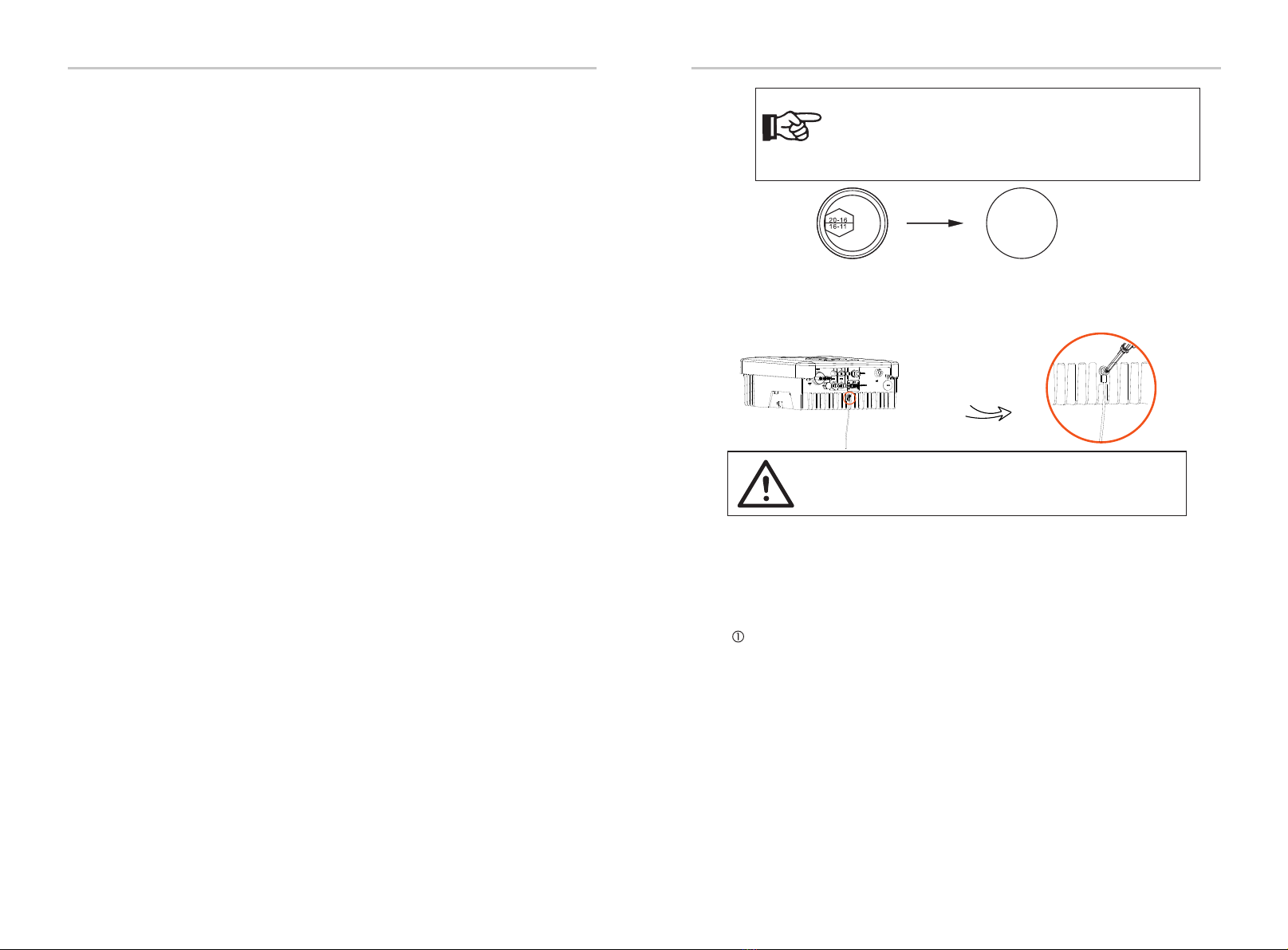
NOTE!
Earth Connection
Screw the ground screw with allen wrench shown as follow. (φ4 hexagon
wrench.torque: 1.5±0.2N.m)
WARNING!
Be sure the ground wire must be connected!
5.5.2 Communication interface
This product has a series of communication interfaces: such as
Wi-Fi, RS485/ Meter/ DRM are used for communication and USB is used for
Firmware updating. Operating information like output voltage, current,
frequency, faulty information, etc., can be delivered to PC or other
monitoring equipment via these interfaces.
Wi-Fi
This inverter provides a Wi-Fi port which can collect information from inverter
including status, performance and updating information to monitoring website
via connecting Wi-Fi dongle (optional).
Connection steps:
If the AC cable you choose is 16mm² or larger, you need to
break the connection between the two rubber rings which
make up the rubber insert as below.
1). Insert the Wi-Fi dongle (optional) into "DONGLE" port at the bottom of
inverter.
2). Connect Wi-Fi dongle (optional) with the router (see Wi-Fi Setup Guide
for details).
3). Set power station information on our website.
Selection of Fuses and Cables connection
Mini cable(AC line cable)shall be short circuit protected and thermal overload
protected.
Always t the input cable with fuse. Normal gGs (US: CC or T ) fuses will protect the
input cable in short circuit sistuation. They will also prevent damage to adjoining
equipment. Dimension the fuses according to local safety regulations, appropriate
input voltage and the related current of the solar inverter.
AC output protected by external fuse (gG rated current 25 A/ 250 VAC for 3.0 KW/ 3.3
KW; 32 A/ 250 VAC for 3.6 KW/ 4.2 KW/ 4.6 KW/ 5.0 KW/ 5.5 KW/ 6.0 KW) provides in all
live connections to the AC supply.
The rated short circuit breaking capacity of the above protective device shall be at
least equal to the prospective fault current at the point of installation. See section
technical data of this manual details.
AC output cable: Cu; L, N,PE: 3*4.0 mmfor 3.0 KW/ 3.3 KW/ 3.6 KW and 3*5 mm for 4.2
KW/ 4.6 KW/ 5.0 KW/ 5.5 KW/ 6.0 KW @40℃ ambient temperature with a max length
of 5 m, with operating time of the fuses is less than 5 seconds, installation method
B2 according to EN60204-1:2006, annex D: cable in conduit cable trunking system,
number of loaded circuit only one. Use H07RNF(cord designation 60245 IEC66) for
anambient temperature of 40℃ or less and use 90℃ wire for ambient temperature
between 40℃ and 60℃.
Note 1: For conditions differing from those mentioned above, dimension the cables
according to local safety regulations, appropriate input voltage and the load and
the load current of the unit.(You can choose a thicker cable but the fuses must rated
according to the rating of the
cable.)
Note 2: Fuses must be approved by Notiöed Body.
Inverter is not provided galvanic isolation from the mains to the PV array, feedback
current to the array is 25A/ 250 VAC for 3.0 KW and 3.3 KW; 32A/ 250 VAC for 3.6
KW,4.2 KW, 4.6 KW, 5.0 KW, 5.5 KW and 6.0 KW based on the fuse provided in the
mains. Also in the worst case the reverse current comprises the sum of the short-
circuit currents of all intact lines. Therefore the current-carrying capacity of the
components and subassemblies provided in the end-use system(connectors,
cables, junction box, switch ger, etc. ) and the reverse current PV modules shall be
considered based on the feedback current and reverse current. The direct
current(DC) circuit breaker or fuse between each solar generator and inverter shall
be provided based on solar inverter input ratings. Select DC cables based in the
above inverter back-feed current and ISCPV rating and Vmax ratings.


