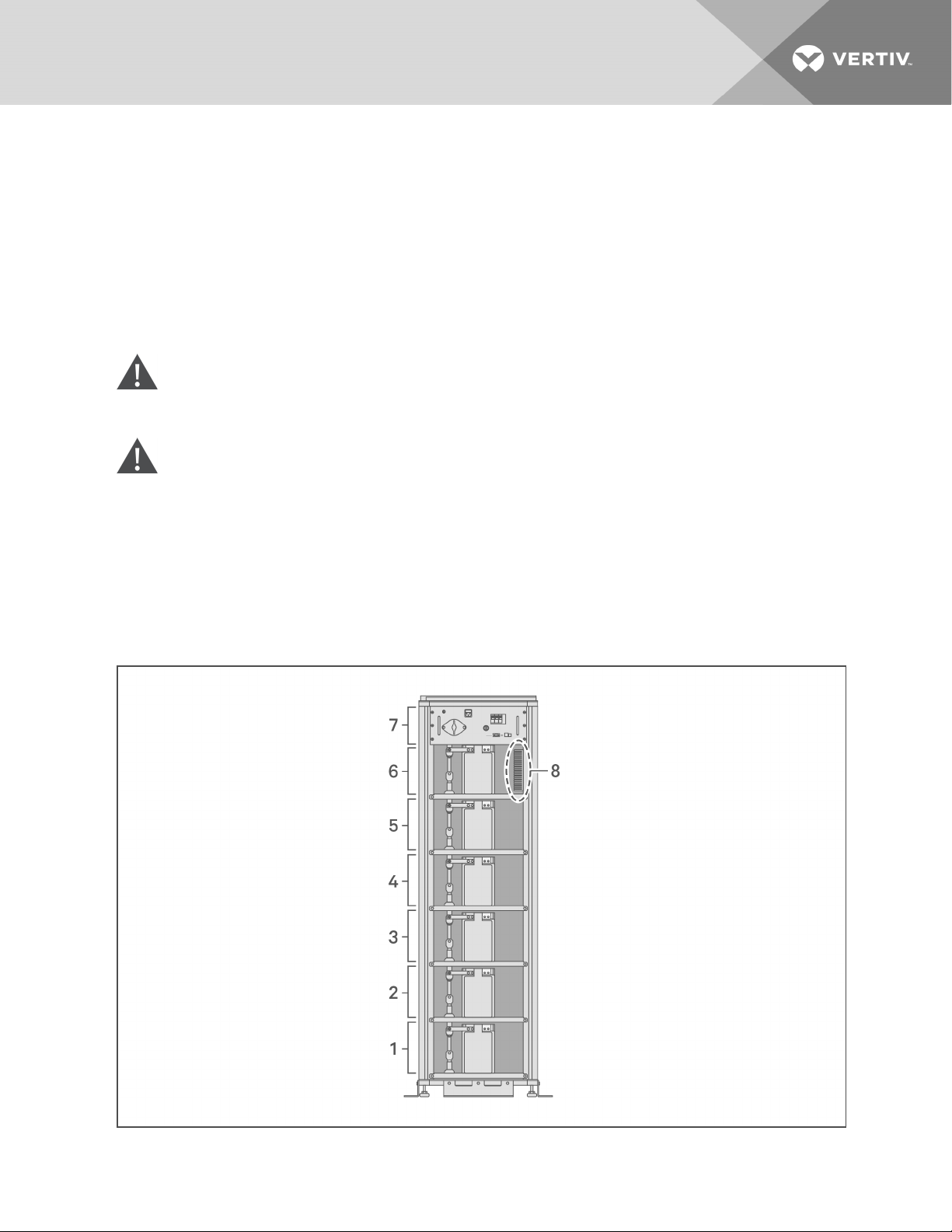
Figure 2.2 Power Chassis Assembly
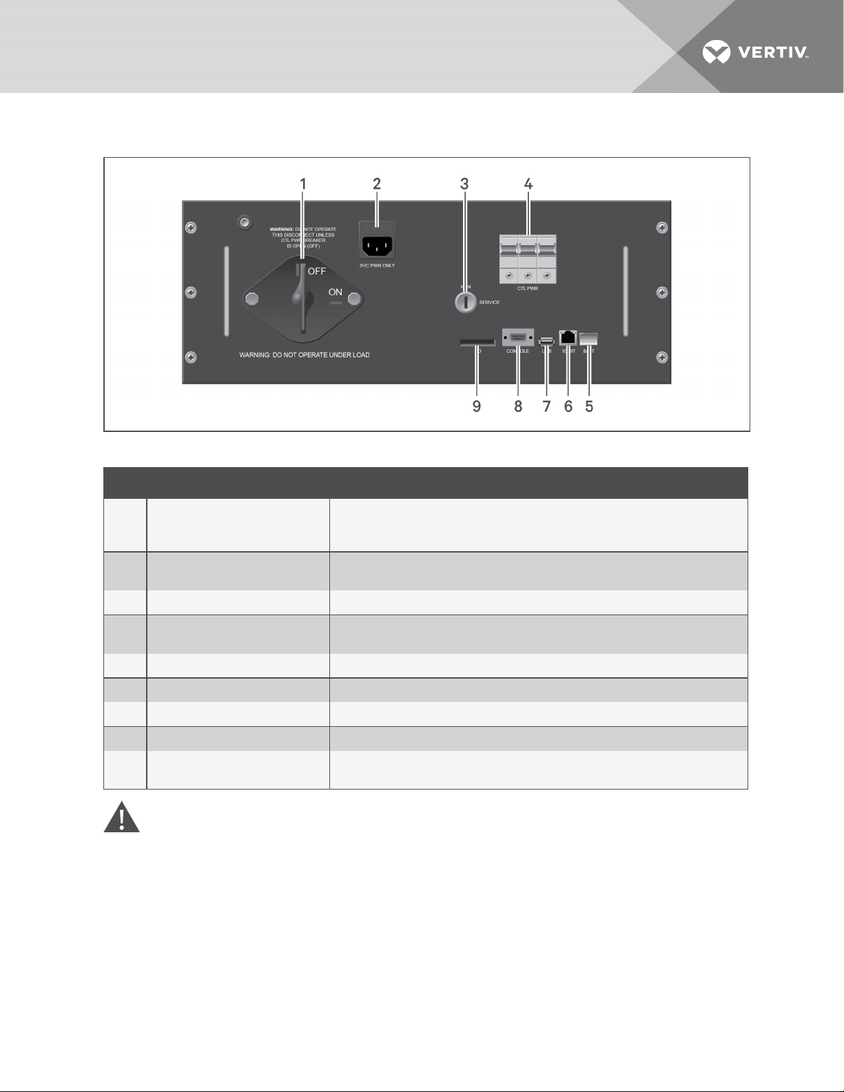
ITEM NAME DESCRIPTION
1S1 maintenance disconnect with
lock-out tag-out feature
Used to isolate the battery rack from the DC bus.
Warning!:Do not operate when the CTL PWRBREAKER is closed, except as
specifically directed when logged into the service console.
2Service power input jack (90-
208VAC 50/60Hz)
For use by Vertiv service personnel only. Provides control power for servicing the unit
when battery and DC bus power are unavailable.
3 RUN/SERVICE key switch For use by Vertiv service personnel under guidance from tech support only.
4Control power breaker (CTLPWR)
and shunt trip Interrupts control power from the battery.
5 Battery (BATT)interface Communications connection to battery modules.
6 100BT interface Ethernet interface for Modbus/TCP.
7 USBinterface Connection for retrieving data logs and commissioning information.
8 CONSOLE interface RS-232 interface for Vertiv service personnel use only.
9 SD card interface Contains the BMS firmware and data logs.
Important:Never remove the SDcard from the SDslot on the PCA.
Table 2.3 Power Chassis Assembly Descriptions
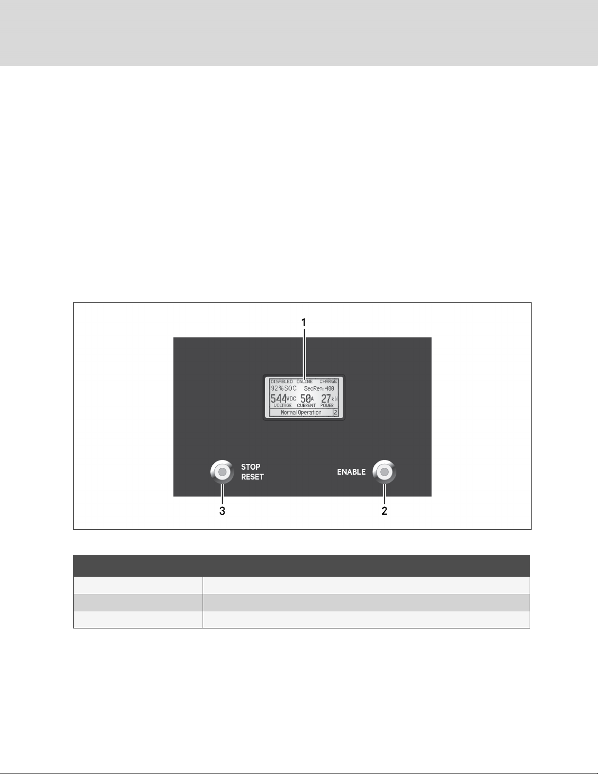
CAUTION: ALWAYSperform the following procedure before opening or closing the S1
maintenance disconnect. Failure to follow this procedure may result in damage to your
equipment.
When the Vertiv HPLLithium Ion Energy Storage System is online, the S1 maintenance disconnect may
be opened.
To open the S1 maintenance disconnect:
1. Verify the RUN/SERVICE key switch is in the RUN position.
1 Overview 3