Vessel GT-1400P User manual

0

For Safe Use
1
Thank you very much for having purchased the "VESSEL Air Impact
Wrench GT-1400P."
Please read this manual carefully and understand its contents for the safe
and correct use of the air tool.
Description
The air impact wrench is a hand-held pneumatic tool that is driven by
compressed air. It incorporates in itself the impact-driven rotation
mechanism for tightening/loosening screws, bolts, nuts, and other
fastening devices.
Warning: Read these instructions carefully before operating,
maintaining or servicing this tool.
■The following icons represent the degree of danger that can be induced by
user’s action or environment. Please observe all the instructions presented
in this manual as they are important for personal and public safety.
Warning Indicates possibility of serious or
fatal injuries when
instructions are not followed.
Caution
Indicates possibility of injuries or property damage when
instructions are not followed.
※Depending on circumstances, failure to follow the
instructions
given in the "Caution" section could lead to
serious
consequences.
■Please keep this manual for your ready reference.
■In case this manual or any of the warning labels attached to the unit
are lost
or damaged, contact us or the local distributor for replacement.
■Please make sure this manual be kept with the unit when it is handed over
or lent out to a third party.
If you have any inquiries about this product or manual, please contact us or
your local distributor.
Warning
Please read this manual carefully and understand
the
contents fully before use.
Warning
■Compressed air management
●Specified air pressure should be applied.

For Safe Use
2
Excessive air pressure may
lead to serious accidents or
property damages. Install proper equipment including a
pressure gauge and a reduction
valve in order to keep the
dynamic pressure at the tool end within the specified range.
●Only compressed air should be applied.
The air impact wrench is a tool driven by normal
compressed air. There will be a risk of explosion if other
high-
pressure gases like oxygen, acetylene, and propane
are used for the tool.
●Choose the appropriate air hose.
Use oil- and abrasion-resistant air hoses for the required
air
pressure and of the recommended inner diameter. Avoid
using deteriorated or excessively long hoses.
●Prevent air leakage.
Make su
re that air plugs be firmly attached to the air hose. If
the air hose comes off due to loose connection, it will
bounce around by the force of compressed
air and may
cause personal injuries or property damages.
Warning
■Work environment
●Keep the work area clean and bright.
Dark or cluttered work environment leads to accidents.
Keep the area tidy and well-lit.
●Do not use the air tool in explosive atmosphere.
This unit may create sparks, which may cause explosion.
Warning
■Work clothes
●Wear appropriate work clothes.
Do not wear baggy clothes, accessories, etc, which might
be caught in revolving parts. Long hair should be tucked
under a cap to keep it away from the tool.
●Wear protective gears.
Wear protective gears suitable for the task,
including a
helmet, protective goggles, earplugs, a dust mask,
anti-vibration gloves and safety shoes, etc.
Warning
■General precautions
●Beware of moving parts.
Keep your hands and cloth away from the moving parts as

For Safe Use
3
they may be caught in them.
●Keep a good posture while working.
Keep a good posture and hold the tool firmly in case of an
unexpected situation.
●Avoid accidental start-up.
Make sure the trigger is released before connecting the air
hose to the unit. Be careful not to press the trigger
when
carrying the air tool.
●Hang the tool securely.
If the tool is suspended by a balancer,
etc. check whether
the equipment is securely installed.
Conduct a regular
maintenance on the suspending equipment as well.
●Keep the tool away from electricity.
The air tool is not insulated against electricity.
●Stop using the tool if you notice any abnormalities.
If you notice any abnormalities, stop using the tool
immediately and contact us or your local distributor for
maintenance, inspection, and repair.
Warning
■Miscellaneous
●Use the tool only for its intended applications.
It may lead to an unexpected accident if the tool is used for
purposes other than those specified in the manual.
●Do not attempt any modification.
Do not
modify the unit. Any modification will void the
warranty and may cause a hazardous situation.
●Do not remove any parts.
Also, do not use the tool if any of its parts or screws has
been removed or missing. It may result in a hazardous
situation.
●Shut off the air supply and detach
the air hose from
the tool;
・ when the tool is not in use
・ when the tool is kept in storage
・ when maintenance is performed
・ when the tool tip (bits / sockets) is replaced
・ when there is any sign of danger or malfunction

For Safe Use
4
Caution
■Basic precautions for operating air tools
●Pay attention.
Stay alert while using the air tool and do not act
thoughtlessly. Also, avoid using the tool when you are tired
or under the influence of drug, alcohol, or medication.
●Keep bystanders away.
Do not let bystanders get close to your operation.
Especially, children should be kept away.
●Do not overload the air tool.
If the tool is operated beyond the specified output range, it
will damage the tool and lead to malfunction.
●Beware of the exhaust port.
Direct the exhaust air away from your eyes and ears.
Otherwise, it can cause accidents or diseases as it contains
oil and it may blow grit or other debris in your face.
●Handle the tool with care.
Do not throw or drop the tool. It may lead to damage or
malfunction if it is handled roughly or forcefully.
●Do not abuse the air hose.
Do not carry, raise or lower the tool by the air hose
.
Damaged hoses increase the risk of accidents.
●Do not drop the tool from a high place.
Equipment like a safety strap should be used
to prevent the
tool from falling when working at high places.
●Store the tool in a safe place.
If the tool is not to be used for a
period of time, conduct
maintenance and keep it in a safe, dry place
. It should be
kept out of the reach of children.
●Be aware of laws.
There are laws and regulations
that may regulate or limit the
use of this product.
Please make sure that the use of this
product does not violate any laws and regulations.
●Take breaks.
Continuous work with
out taking appropriate breaks could
lead to illness, take breaks as required.
If you feel
abnormalities, such as pain,
immediately stop using the tool

For Safe Use
5
and consult a physician.
Caution ■Maintenance, inspections and repairs
●Check before use.
Make
sure the unit has no loose screws/bolts and fittings
and no damaged parts. If the unit is operated despite such
problems, it could lead to a hazardous situation as well as
decrease the performance.
●Conduct inspection and maintenance regularly.
Regular
inspection and maintenance are necessary for safe
and efficient performance of the tool.
●
Please contact us or the local distributor for repair or
parts replacement.
Never disassemble the unit or replace parts
by yourself.
Warranty on any of our produc
ts shall be void if defect is
caused by abuse, neglect, improper repair, improper fit, or
any use unintended by the manufacturer.
Prior to Use
・Open the package and check if all the parts are inside without shortage
and damage.
・Be sure to read and understand this manual thoroughly before handling
this product.
・Keep the instruction manual in hand and refer to it whenever needed.
・Store the instruction manual in a safe place. If the manual is lost or
damaged, contact us or your local distributor for a new copy.

Applications
6
・This product is an air tool that uses compressed air as its power source
and has been designed and developed for tightening and loosening
bolts/nuts.
This air tool should not be operated;
* if the application is outside the specified operating range.
* if any part of it has been modified or altered.
* if normal compressed air is not available. Never use other power
sources, such as oxygen, acetylene, and propane, etc.
* near water or in ignitable environments.
* in any way unintended by the manufacturer.
Icons for safety instructions
This unit may
cause vibration.
Wear
protective
goggles.
Wear earplugs.
Read the manual
before use.

How to use
7
PIPING MODEL
SPECIFICATIONS
Sound Level
PA
L〔dB〕91.3
WA
L〔dB〕102.3
Vibrations Level 〔m/s²〕 28.32
Uncertainty K 〔m/s²〕 6.27
CE DECLARATION OF CONFORMITY
VESSEL CO.,INC.
FUKAEKITA2-17-25,HIGASINARIKU,OSAKA,
JAPAN
PRODUCT: AIR IMPACT WRENCH
MODEL: GT-1400P
DIRECTIVE: 2006/42/EC(98/37/EC) , EN 792
STANDARDS: ISO 20643(ISO 8662-1),ISO 28927-2(ISO 8662-7)
ISO 15744
declared vibration emission value in accordance with EN 12096
DATE: Dec/10/2008
APPROVED BY Yasushi Shiomi
Air Tool
Oiler Filter
Air Compressor
Regulator
Drain Tap

How to use
8
・For operating the tool, make sure to follow the procedures described
in this instruction manual.
・Do not use the tool:
* if the socket/bit is not properly mounted or not compatible in size.
* if the work environment does not allow you to keep a stable posture,
secure a firm grip on the tool or to operate the tool properly.
* if the floor is slippery or not level.
* if it is used for other purposes than tightening or loosening screws.
* if it has been modified or has any parts missing or lost.
* if the input air pressure is higher than the specified value.
* if more than the specified working torque is required.
・When the tool is not in use or left unattended, shut off the air supply
and detach the air hose from it.
Preparations before use
●Check the air pressure
The specified air pressure for this air tool is 0.6 MPa. Do not apply air
pressure outside this specified range as it influences performance,
lifespan and safety.
●Remove the drain
When moisture or impurities like rust in the pipe get into the mechanism,
it may cause malfunction. Remove accumulated drain in the compressor
before use. To secure dry air supply, install an air filter in order to prevent
moisture and any impurities.
●Use an appropriate air hoses
Please refer to Specifications for choosing an air hose of the appropriate
size for the applied air supply. If the internal diameter of the air hose is
too small, sufficient power may not be obtained as air pressure cannot
increase efficiently. It also happens when the hose is too long.
●Install the plug
Use a spanner of No.19 to hold Air Inlet Bushing
and fasten the plug.

How to use
9
●Air coupling
When using the air coupling included in the package, purchase a
compatible connector. When connecting a hose directly to this product,
purchase a hose connection coupling. In both cases, check the size of
the connected hoses.
●Before the first operation after purchase
When this air tool has been newly installed or the air hose has been
replaced, blow and clean the inside of the hose and piping. Then, idle the
device for a few seconds because lubricant within the mechanism has to
be blasted out with exhaust air.
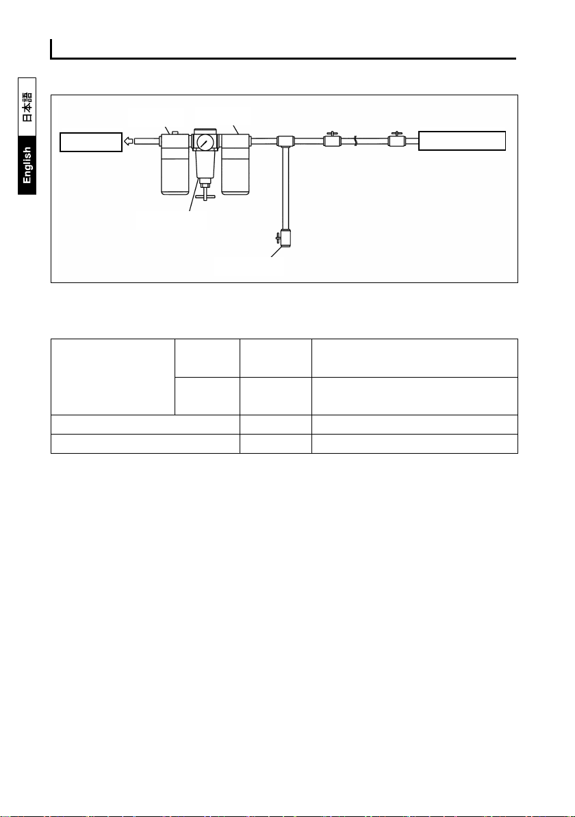
●Lubrication
Lubricate the unit regularly for smooth operation of the motor part and to
remove impurities. If you install a lubricator, it will lubricate the tool
automatically. Or, you can lubricate manually from the air supply port
before or after use. (ISO VG10 or equivalent hydraulic oil.)
●Idle the unit after lubrication
Please idle the unit for several seconds after lubrication has been
conducted because oil will be discharged with exhaust air. Do not idle
the unit while a tip tool is attached.
●Tool tips (sockets / bits / extension bars, etc.)
Do not install a tip for hand tools. There will be a risk of accident as the tip
may be destroyed. Be sure to use a tip for power tools.
●Tightening bolts/nuts
To tighten bolts/nuts, first tighten bolts/nuts by hand for a couple of thread
pitches. After tightening is complete, immediately release the lever and
stop the tool. Excessive tightening will cause bolts to be broken and life
of the hammer parts to wear/tear quickly.
●When bolts/nuts cannot be loosened
In case bolts/nuts cannot be loosened or tightened as required, please
adopt an impact wrench with a higher capacity.
●Keep the tool away from organic solvents
Be aware that dipping the tool in the organic solvents will deform the tool.
●In cold areas
Moisture inside the tool may freeze in winter. Be sure to lubricate the tool
to remove the moisture after use.

How to use the tool
10
How to use the tool
●Starting and stopping
1.Connecting the air coupling.
2.Supply air with a compressor.
3.Press the throttle lever to start the unit.
4.Release the throttle lever to stop the unit.
●Changing the direction of rotation.
When the Reverse Valve is set to "R"
it rotates clockwise.
When it is set to "L," it rotates counter
clockwise.
Do not operate the Reverse Valve while
pressing the throttle lever.
●Adjusting the torque.
Torque can be adjusted by the Adjustment Valve.
"1" is the minimum and "4" is the maximum.
●Installing sockets.
There is a pinhole on the point of the anvil
(Drive part).
Align the pinholes of the socket and anvil
and attach the socket with the pin and O-Ring.
Install as shown in the figure.
If it is not securely attached, the socket or bit may detach and fly off.
Do not attach the socket or bit when the tool is idling.

How to use the tool
11
About handling
* Do not touch any rotating parts. It is very dangerous and could lead to
injury.
* Do not idle the tool without load.
* Confirm the rotation direction before starting the unit.
* Be sure to turn off the air, when work is finished as well as when
bits/sockets and the parts are to be changed.
* Do not direct the exhaust towards people or fire. The exhaust is
dangerous since it contains oil.
* Do not touch the tip tool and screws immediately after the work because
they became hot from friction during work.
* When you notice any abnormalities, stop working and turn off the air
supply.
Maintenance / Repairs
・We recommend periodic inspections for safe, worry-free use. If
inspections are neglected, it may affect the performance, lifespan and
safety of the product.
・Inspection (maintenance) should be conducted only by those who
carefully read and fully understood the instruction manual for this
product.
・Contact the local distributor for repairs. Do not repair the unit by yourself.
Points of regular maintenance
When conducting maintenance, be sure to remove the hose coupling and
do not supply any air.
The durability of parts depends on how frequently the unit is used.
Please apply for inspection / repairing in case you notice any abnormality in
impact and revolving sounds. (eg. in case of any abnormalities in the
rhythm of hammering, deterioration in efficiency, and working torque
degradation).

Maintenance
/
Repairs
12
●Anvil ( drive part on the tip)
Worn out …It will deteriorate the performance and decrease efficiency.
Early replacement of parts is recommended.
Cracks …..Stop using and seek professional help for repair.
●Socket
Worn out square and hexagonal heads
………..…It may deteriorate the performance and the socket may detach
from the anvil.
Cracks …..Stop using and replace it with a new one.
●Hose couplings
Loose screws …..Tighten them since it is dangerous if the hose comes off.
Worn out ……Replace with new parts since the coupling may come off
if the connection is loose.
●Throttle lever
Return condition …Confirm whether the lever returns properly. It is very
dangerous to use the tool continuously if the lever
does not return properly because the tool will start
suddenly after connected. If the lever does not
return, please request repairs.
●Bolts for each part
Loose bolts ………. It may lead to air leaks and malfunctions. Please
re-tighten the bolts.
●Surface damage
Cracks ……………. Stop using and request repairs.

Troubleshooting
13
Troubleshooting
Trouble
Cause
Action
1. No rotation
Air is not provided. Turn on the air.
The hose is twisted. Straighten the hose.
Air pressure is low. Adjust the air
pressure.
Parts are rusted due to a lack
of lubrication. Lubricate the unit.
Dirt contamination. Request overhaul
Malfunction (worn out /
damaged, etc.) on motor
and hammer.
Request for parts
replacement
2. Rotation is
uneven.
Rate of air flow is
inadequate. Confirm air flow rate.
Air pressure is low. Adjust air pressure.
Parts are rusted due to a lack
of lubrication. Lubricate the unit.
3.Rotation does
not stop.
Change of shape of the
Throttle Pin.
Request for parts
replacement
Change of shape of the
Throttle Valve.
Request for parts
replacement
Breakage of throttle valve.
Request for parts
replacement
Contamination by a foreign
substance in the throttle
valve.
Request overhaul
4.Reverse Valve /
Adjustment Valve
is loose.
Stop spring is worn out,
damaged or rusted. Request overhaul
5. Reverse Valve /
Adjustment Valve
does not work.
Rust and dirt contamination.
Request overhaul
6.Socket is loose. Breakage of socket pin. Request for parts
replacement
7. Air leakage
Trouble with the valve (O-
ring
damage, ball rust, or
worn-out, damaged and
rusted springs etc).
Request for parts
replacement

Troubleshooting
14
8.Abnormal noise
Spare parts came loose. Request overhaul
Worn out and damaged
bearings.
Request for parts
replacement
Damage to the hammer case
and impact part.
Request for parts
replacement
Worn out and
damaged rotor
blade.
Request for parts
replacement
The rotor blade does not
come out at rotating.
Request for parts
replacement
Run out of lubrication and oil.
Lubricate the unit.
9.
It rotates without a
load but with a load
it does not rotate
and the power
decreases.
Parts of the hammer are
damaged.
Request for parts
replacement
10.Water comes
out. The drain is clogged. Clean the drain.
Request repairs immediately when the tool is in a defective and abnormal
condition, etc., since it could lead to a product malfunction and accident.
Please contact our distributor for repairs.
Storage
Please store the air tool in a safe location and be aware of dust, humidity,
dew and freezing.

Exploded diagram drawing & Parts list
15
Specification
Unit GT-1400P
Square Drive Size mm 12.7
Capacity(Bolt Dia.)mm 14
Working Torque Range
Nm 49.0~294.1
Weight kg 2.25
Overall Length mm 182
Free Load rpm 7000
WorkingAir Pressure MPa 0.6
Air Consumption ㎥/min 0.35
Air Compressor kw 0.75 or bigger
Air Hose Inner Dia. mm 6.35
Hose Coupling Rc 1/4
Accessories
VESSEL Air Coupling (BPB-2) 1 pc
“L” Wrench(A/F 4mm) 1 pc
Description

Exploded diagram drawing & Parts list
16

Exploded diagram drawing & Parts list
17
Index
No.
EDP
No. Description Size
Number
Required per
unit
1 833001 Cover Seal 1
2 833002 Hammer Housing Complete 1
3 833003 Hex Cap Bolt ※M5×20 4
4 833004 Washer, Spring ※M5 4
〈5〉
833005 Spring S3.8×7×0.5(Installed No. 2) 1
〈6〉
833006 Ball, Valve, Reverse ※4mm(Installed No. 2) 1
〈7〉
833007 Bushing, Pressed (Installed No. 2) 1
8 833008 Washer, Thrust 1
10
833010 Anvil Complete 1
〈11〉
833011 Ring, Retainer (Installed No. 10) 1
〈12〉
833012 O- Ring, Retainer ※P7(Installed No. 10) 1
13
833013 Pin, Hammer 1
14
833014 Hammer 1
15
833015 Frame, Hammer 1
16
833016 Driver 1
17
833017 Shim 1
18
833018 Front Gasket, Motor Housing 1
19
833019 Motor Housing. Cp. 1
〈20〉
833020 Bearing ※6001 (Installed No. 21) 1
〈21〉
833021 Endplate Cp, Front (Installed No. 19) 1
〈22〉
833022 Cylinder Cp. (Installed No. 19) 1
〈23〉
833023 Pin, Cylinder ※SP3×10 (Installed No. 22) 2
24
833024 Rotor 1
25
833025 Blade, Rotor 5
26
833026 Endplate Cp, Rear 1
〈27〉
833027 Pin, Rear Endplate ※SP3×8 (Installed No. 26) 1
〈28〉
833028 Bearing ※6001(Installed No. 26) 1
29
833029 Rear Gasket, Motor Housing 1
30
833030 Backplate Complete 1
31
833031 Washer, Spring ※M5 4
32
833032 Hex Cap Bolt ※M5×20 4
33
833033 O-ring, Reverse Valve ※P11 1

Exploded diagram drawing & Parts list
18
34
833034 Valve, Reverse 1
〈35〉
833035 Spring, Adjustment Valve Retainer S3.8×7×0.4(Installed No. 30) 1
〈36〉
833036 Ball, Adjustment Valve Retainer ※4mm(Installed No. 30) 1
37
833037 O-ring, Adjustment Valve ※P11 1
38
833038 Valve, Adjustment 1
39
833039
Pin, Valve, Adjustment ※SP3×20 1
40
833040 Lever, Throttle 1
41
833041 Pin, Throttle Lever ※SP3×16 1
42
833042 Pin, Throttle 1
43
833043 Ball, Valve ※3/8 1
44
833044 Spring, Throttle Pin 1
45
833045 O-ring, Air Inlet Bushing ※P12 1
46
833046 Bushing, Air Inlet Rc1/4 1
47
833047 Plug ※Rc1/4 1
Parts with < > marked shall not be supplied individually even if ordered since it is an integrated
component.
●The contents of this manual are subject to be changed without notice.

Exploded diagram drawing & Parts list
19
Table of contents
Other Vessel Impact Driver manuals

Vessel
Vessel GT-P12 User manual

Vessel
Vessel GT-1600VP User manual

Vessel
Vessel HFB-300-1 User manual

Vessel
Vessel GT-P10S2 User manual

Vessel
Vessel GT-1700BX User manual

Vessel
Vessel GT-3500GE-V-US User manual

Vessel
Vessel GT-3500GE Assembly instructions

Vessel
Vessel GT-S6CD User manual

Vessel
Vessel GT-3800PX User manual

Vessel
Vessel GT-3500GE Assembly instructions
Popular Impact Driver manuals by other brands

Hitachi
Hitachi WR 22SA Technical and service manual

CP
CP CP734H Series Operator's manual

RED ROOSTER
RED ROOSTER RRI-1061 manual

Milwaukee
Milwaukee M18 FUEL 2862-20 Operator's manual

DeWalt
DeWalt Klein Tools BAT20-CW instruction manual

Schneider Airsystems
Schneider Airsystems SGS 2000 Original operating manual