TECHNICAL DATA
Note: To improve the performance, the specifications are subject to change without notice.
CHAPTER 1.
INTRODUCTION
Engine Type
Displacement
Fuel Tank Capacity
Fuel Mixture Ratio
Revolution(idling)
Revolution(loaded, impact)
Revolution(non loaded, max)
Maximum Output
Maximum Torque
Compression Rate
Fuel Consumption Rate
:Two Stroke, Forced, Air Cooled, Single Cylinder
: 46.5cc, Φ43x32mm(Inner bore size x stroke)
: 1 liter
: 25:1(gasoline : 2 cycle oil)
: 2700 rpm ±250
: 7120 rpm
: 9880 rpm
: 2.3 Ps/7500 rpm
: 0.34 kg-m/5500 rpm
: 7.1 : 1
: 380 g/Ps.h
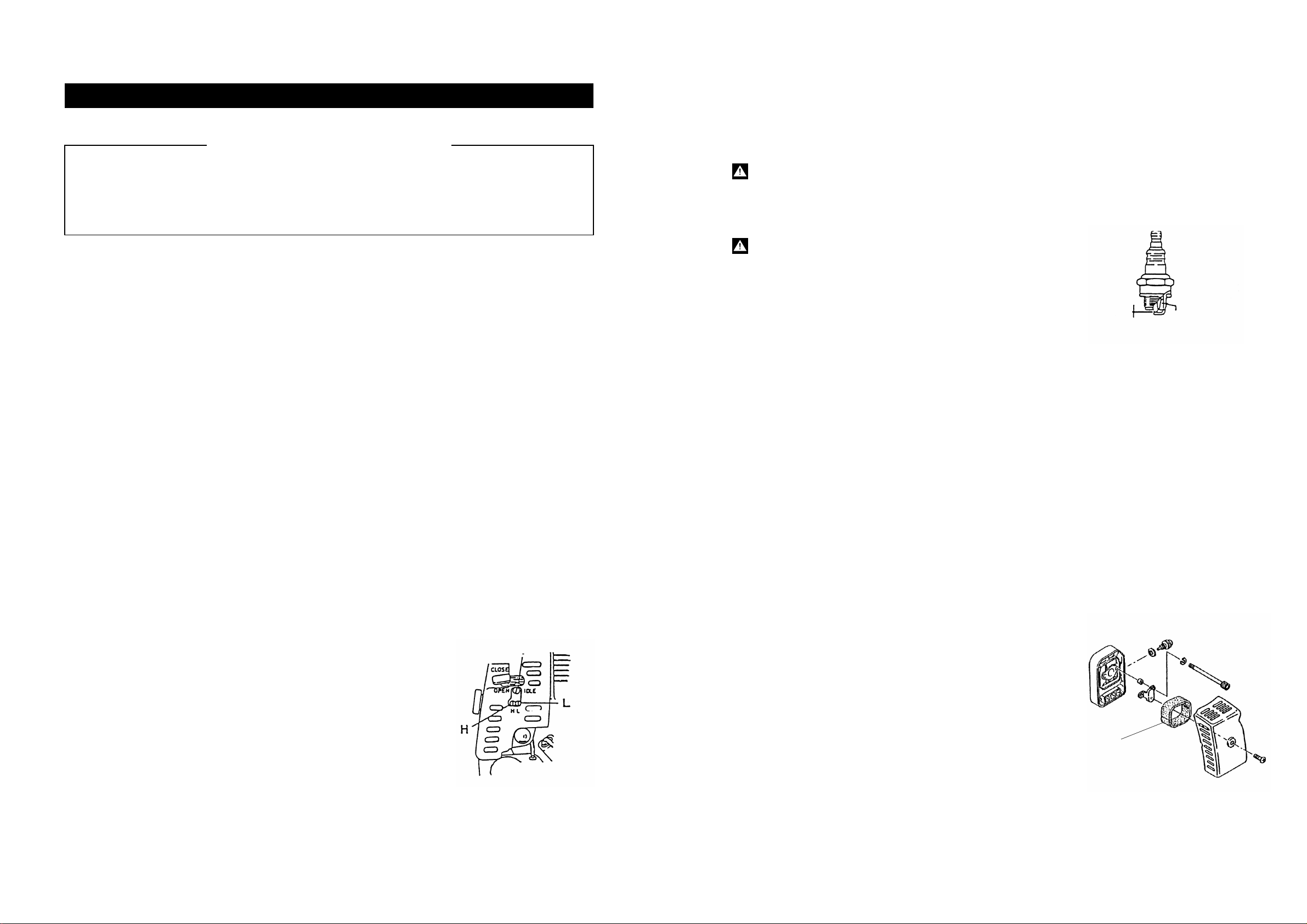
Ignition Type
Spark Plug Type : Electronic
: NGK BPMR6A
Vibration Unloaded
Loaded : 4m/S2
: 19m/S2
Noise Idle
Loaded : 78dBA
: 100dBA
Carburetor Type : Diaphragm
Impact Square Drive Size
Fastening Torque Range
Free Speed
: 25.4 mm(1")
: 1030Nm(Full Throttle : 760ft. lbf)
800Nm(Half Throttle : 590ft. lbf)
: 1200 rpm
Capacity Bolt Diameter : 32 mm (1 1/4")
Weight Without fuel : 19.50 kg (42.99 lbs.)
Overall Dimensions Length
Height
Width
: 700mm (28")
: 330mm (13")
: 390mm (15")
Accessories Hex Key Wrench
Spark Plug Wrench
Spanner
4mm 1pc.
5mm 1pc.
6mm 1pc.
1pc.
10-13mm 1pc.
GT-3500GE GASOLINE ENGINE IMPACT WRENCH is ahigh quality tool with self-contained
heavy duty and high power two cycle engine as power source. And its unique designof impact
mechanism withVESSEL pneumatic V-Hammer ultra light weight impact wrench series,even
small engine (46.5 cc) can create higher fastening torque with enormous light weight only
19.50kg (42.99 lbs.)
Because of self-contained high power two cycle engine, it is veryeasily mobile to carry by one
man to any construction sites in the rain forest, hill or desertsuch remote areas where electricity
supply or air compressor, generator are not available.
The capacityof this tool is 32mm (1 1/4") bolt size and ideal for fastening and loosening bolts
of wood sleepers at railroad construction and many more applications.
2
1
●
●
●
●
●
●
●
●
●
●
●
●
●
WARNINGS AND SAFETY INSTRUCTIONS
CHAPTER 2.
Read these instructions carefully before operating, maintaining or servicing this tool.
Please keep these instructions in a safe accessible place.
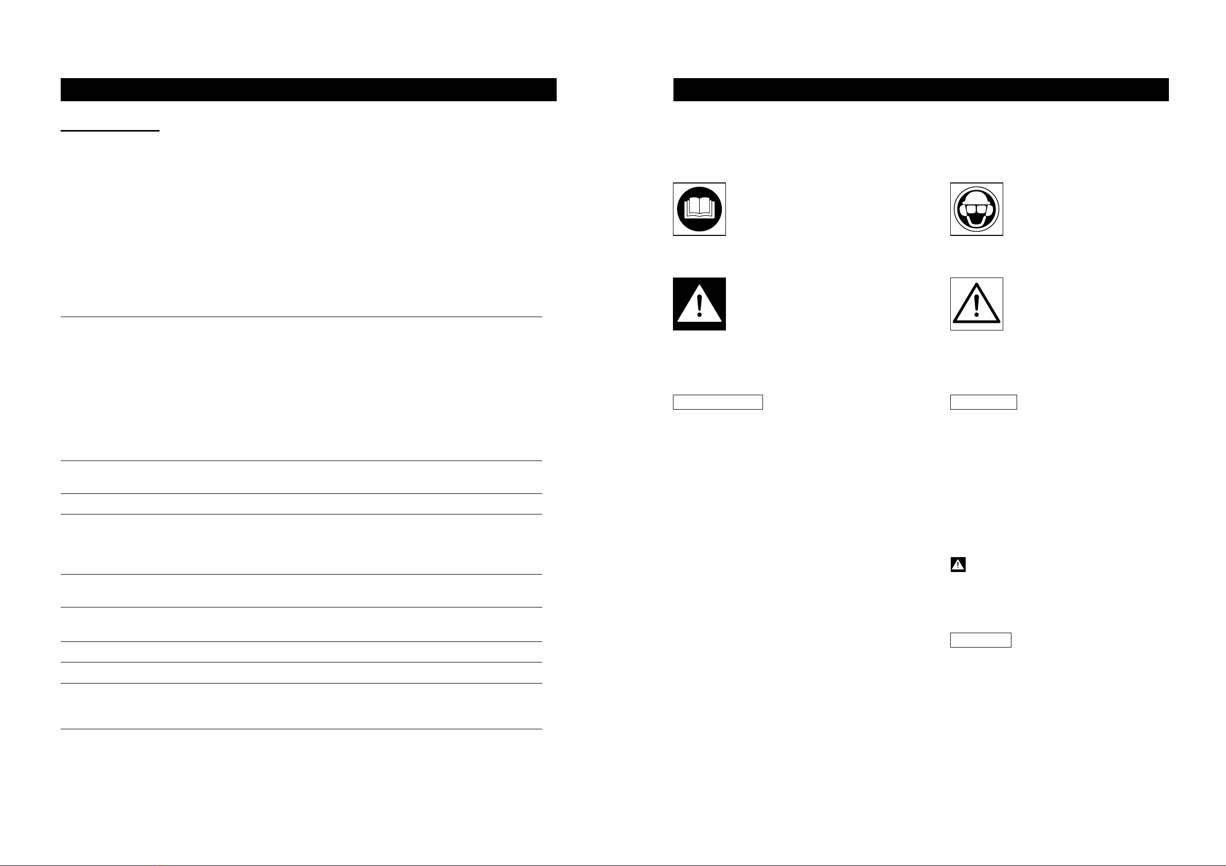
Read to fully understand and
observe the following safety
precautions and warnings.
Careless or improper use of
tool may cause serious or fatal
injury.
WARNING!
Indicates instant possibility of
severe personal injury or loss
of life, if instructions are not
followed.
Always wear eye, head and
ear protectors when using this
tool.
CAUTION!
Indicates apossibility of per-
sonal injury or equipment dam-
age, if instructions are not
followed.
Always wear a safety face shield or goggles.
Always wear heavy, long pants, boots and
gloves. Do not wear loose clothing, jewellery,
short pants, sandals or go barefoot. Secure
hair so it is above shoulder length.
Do not operate that tool when you are tired,
ill or under the influence of alcohol,drugs or
medication.
Never let achild or inexperienced person
operate the machine.
Wear hearing protection.
Never start or run the engine inside a closed
room or building. Breathing exhaust fumes
can kill.
Keep handles free of oil and fuel.
Keep hands away from anvil.
Do not grab or hold the unit by rotating anvil.
Hold the handles firmly with both hands and
make sure to stand on the firm base or ground.
Do not touch spark plug, high voltage cord du-
ring operation as it may cause electric shock.
To avoid burn do not touch those places like
engine, muffler, exhaust where get very hot
during in use or even after stop engine until
it gets cool for the time being.
When operation is prolonged, take abreak
from time to time so that you may avoid pos-
sible whitefingerdiseasewhich is caused
by vibration.
Operator safetyInspectthe entire tool before each use. Re-
place damaged parts. Check for fuel leaks and
make sure all fasteners are in place and se-
curely fastened.
Replace parts that are cracked, chipped or
damaged in any way before using the tool.
Keep others away when making carburetor
adjustments.
Use only accessories as recommended for this
tools by the manufacturer.
●
●
●
●
Tool safety
Never modify the tool in any way. Do not use
your tool for any job except that for which it is
intended.
●
●
●
●
●
Fuel safety
Mix and pour fuel outdoors and where there
are no sparks or flames.
Use a container approved for fuel.
Do not smoke or allow smoking near fuel or
the tool or while using the tool.
When filling up fuel, stop engine and make
sure engine is cool and choose the places
where no flamables and well ventulation.
Wipe up all fuel spills before starting engine.
WARNING!