Vessel GT-1700BX User manual


Manufactured by:
17-25, Fukae-Kita 2-chome,
Higashinari-ku, Osaka 537-0001 Japan
Tel : +81 6 6976 7778 Fax : +81 6 6972 9441
E-mail : export@vessel.co.jp
URL : http://www.vessel.co.jp/english/

For Safe Use
1
Thank you very much for having purchased the "VESSELAir ImpactWrench GT-1700BX."
Please read this manual carefully and understand its contents for the safe and correct use of the air tool.
Description
The air impact wrench is a hand-held pneumatic tool that is driven by compressed air. It incorporates in itself the
impact-driven rotation mechanism for tightening/loosening screws, bolts, nuts, and other fastening devices.
Warning: Read these instructions carefully before operating, maintaining or servicing this tool.
■The following icons represent the degree of danger that can be induced by user’s action or environment. Please
observe all the instructions presented in this manual as they are important for personal and public safety.
Warning Indicates possibility of serious or fatal injuries when instructions are not followed.
Caution Indicates possibility of injuries or property damage when instructions are not followed.
※Depending on circumstances, failure to follow the instructions given in the "Caution" section could
lead to serious consequences.
Please keep this manual for your ready reference.
In case this manual or any of the warning labels attached to the unit are lost or damaged, contact us or the local
distributor for replacement.
Please make sure thismanual be kept with the unit when it is handed over or lent out to a third party.
If you have any inquiries about this product or manual, please contact us or your local distributor.
Warning
Please read this manual carefully and understand the contents fully before use.
Warning
■Compressed air management
●Specified air pressure should be applied.
Excessive air pressure may
lead to serious accidents or property damages. Install proper equipment
including a pressure gauge and a reduction valve in order to keep the dynamic pressure at the tool end
within the specified range.
●Only compressed air should be applied.
The air impact wrench is a tool driven by normal compressed air. There will be a risk of explosion if other
high-pressure gases like oxygen, acetylene, and propane are used for the tool.
●Choose the appropriate air hose.
Use oil- and abrasion-resistant air hoses for the required air pressure and
of the recommended inner
diameter.Avoid using deteriorated or excessively long hoses.
●Prevent air leakage.
Make sure that air plugs be firmly attached to the air hose. If the air hose comes off due to loose connection,
it will bounce around by the force of compressed air and may cause personal injuries or property damages.
Warning
■Work environment
●Keep the work area clean and bright.
Dark or cluttered work environment leads to accidents. Keep the area tidy and well-lit.
●Do not use the air tool in explosive atmosphere.

For Safe Use
2
This unit may create sparks, which may cause explosion.
Warning
■Work clothes
●Wear appropriate work clothes.
Do not wear baggy clothes, accessories, etc, which might
be caught in revolving parts. Long hair should be
tucked under a cap to keep it away from the tool.
●Wear protective gears.
Wear prot
ective gears suitable for the task, including a helmet, protective goggles, earplugs, a dust mask,
anti-vibration gloves and safety shoes, etc.
Warning
■General precautions
●Beware of moving parts.
Keep your hands and cloth away from the moving parts as they may be caught in them.
●Keep a good posture while working.
Keep a good posture and hold the tool firmly in case of an unexpected situation.
●Avoid accidental start-up.
Make sure the trigger is released before connecting the air hose to the unit. Be careful not to press the trigger
when carrying the air tool.
●Keep the tool away from electricity.
The air tool is not insulated against electricity.
●Stop using the tool if you notice any abnormalities.
If you notice any abnormalities, stop using the tool immediately and contact us or your local distributor for
maintenance, inspection, and repair.
Warning
■Miscellaneous
●Use the tool only for its intended applications.
It may lead to an unexpected accident if the tool is used for purposes other than those specified in the manual.
●Do not attempt any modification.
Do not modify the unit.Any modification will void the warranty and may cause a hazardous situation.
Also, do not use the tool if any of its parts or screws has be
en removed or missing. It may result in a hazardous
situation.
●Shut off the air supplyand detach the air hose from the tool;
・ when the tool is not in use
・ when the tool is kept in storage
・ when maintenance is performed
・ when the tool tip (bits / sockets) is replaced
・ when there is any sign of danger or malfunction
Caution
■Basic precautions for operating air tools
●Keep bystanders away.
Do not let bystanders get close to your operation. Especially, children should be kept away.
●Do not overload the air tool.

For Safe Use
3
If the tool is operated beyond the specified output range, it will damage the tool and lead to malfunction.
●Beware of the exhaust port.
Direct the exhaust air away from your eyes and ears. Otherwise, it can cause accidents or disea
ses as it
contains oil and it may blow grit or other debris in your face.
●Handle the tool / air hose with care.
Do not throw or drop the tool. It may lead to damage or malfunction if it is handled roughly or forcefully.
Do not carry, raise or lower the tool by the air hose. Damaged hoses increase the risk of accidents.
●Do not drop the tool from a high place.
Equipment like a safety strap should be used to prevent the tool from falling when working at high places.
●Store the tool in a safe place.
If the tool is not to be used for a period of time, conduct maintenance and keep it in a safe, dry place
. It should
be kept out of the reach of children.
●Be aware of laws.
There are laws and regulations that may regulate or limit the use of this product.
Please make sure that the
use of this product does not violate any laws and regulations.
●Take breaks.
Continuous work without taking appropriate breaks could lead to illness, take breaks as required.
If you feel
abnormalities, such as pain, immediately stop using the tool and consult a physician.
Caution
■Maintenance, inspections and repairs
●Check before use.
Make sure the unit has no loose screws/bolts and fittings and no damaged parts. If the unit is operated despite
such problems, it could lead to a hazardous situation as well as decrease the performance.
Regular inspection and maintenance are necessary for safe and efficient performance of the tool.
●Please contact us or the local distributor for repair or parts replacement.
Never disassemble the unit or replace parts by yourself. Warranty
on any of our products shall be void if defect
is caused by abuse, neglect, improper repair, improper fit, or any use unintended by the manufacturer.
How to use the tool
●Remove the drain
When moisture or impurities like rust in the pipe get into the mechanism, it may cause malfunction. Remove
accumulated drain in the compressor before use. To secure dry air supply, install an air filter in order to prevent
moisture and any impurities.
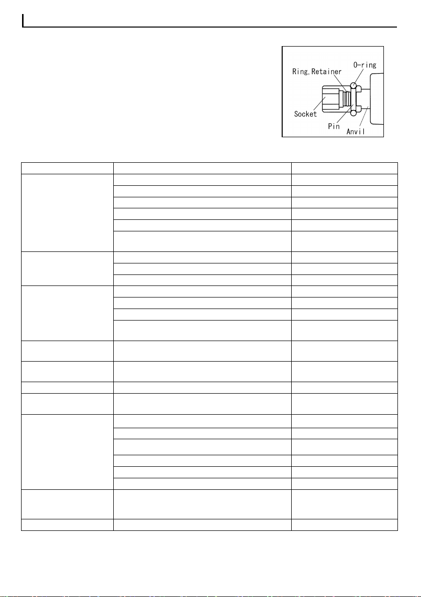
●Use an appropriate air hoses
Please refer to Specifications for choosing an air hose of the appropriate size for the applied air supply. If the internal
diameter of the air hose is too small, sufficient power may not be obtained as air pressure cannot increase efficiently.
It also happens when the hose is too long.
●In cold areas
Moisture inside the tool may freeze in winter. Be sure to lubricate the tool to remove the moisture after use.

How to use
4
●Install the plug
Use a spanner of No.19 to hold Air Inlet Bushing and fasten the plug.
●Air coupling
When using the air coupling included in the package,
purchase a compatible connector. When connecting a hose directly to this product, purchase a hose connection
coupling. In both cases, check the size of the connected hoses.
●Before the first operation after purchase
When this air tool has been newly installed or the air hose has been replaced, blow and clean the inside of the hose
and piping. Then, idle the device for a few seconds because lubricant within the mechanism has to be blasted out
with exhaust air.
●Lubrication
Lubricate the unit regularly for smooth operation of the motor part and to remove impurities. If you install a lubricator,
it will lubricate the tool automatically. Or, you can lubricate manually from the air supply port before or after use. (ISO
VG10 or equivalent hydraulic oil.)
Please idle the unit for several seconds after lubrication has been conducted because oil will be discharged with
exhaust air. Do not idle the unit while a tip tool is attached.
●Tool tips (sockets / bits / extension bars, etc.)
Do not install a tip for hand tools. There will be a risk of accident as the tip may be destroyed. Be sure to use a tip for
power tools.
●Tightening bolts/nuts
To tighten bolts/nuts, first tighten bolts/nuts by hand for a couple of thread pitches. After tightening is complete,
immediately release the lever and stop the tool. Excessive tightening will cause bolts to be broken and life of the
hammer parts to wear/tear quickly.
●When bolts/nuts cannot be loosened
In case bolts/nuts cannot be loosened or tightened as required, please adopt an impact wrench with a higher
capacity.
●Starting and stopping
1.Connecting the air coupling.
2.Supply air with the compressor.
3.When the throttle lever is pulled or pushed, the function starts.
4.When the throttle lever is released (disengaged), the function stops.
●Changing the direction of rotation.
When the right/left switch lever is set to "↷," it rotates clockwise. When it is set
to "↶," it rotates counter clockwise.
Do not operate the rotation switch while pressing the throttle lever.
Torque adjustment is possible by aligning the right/left switch lever mark with
the numbers. "1" is the minimum and "4" is the maximum.

How to use
5
●Installing sockets.
There is a pinhole on the point of the anvil (Drive part).
Align the pinholes of the socket and anvil and attach
the socket with the pin and O-Ring.
Install as shown in the figure.
If it is not securely attached, the socket or bit may detach and
fly off. Do not attach the socket or bit when the tool is idling.
Troubleshooting
Trouble
Cause
Action
No rotation
Air is not provided. Turn on the air.
The hose is twisted. Straighten the hose.
Air pressure is low. Adjust the air pressure.
Parts are rusted due to a lack of lubrication. Lubricate the unit.
Dirt contamination. Request overhaul
Malfunction (worn out / damaged, etc.) on motor
and hammer. Request for parts replacement
Rotation is uneven.
Rate of air flow is inadequate. Confirm air flow rate.
Air pressure is low. Adjust air pressure.
Parts are rusted due to a lack of lubrication. Lubricate the unit.
Rotation does not stop.
Change of shape of the Throttle Pin. Request for parts replacement
Change of shape of the Throttle Valve. Request for parts replacement
Breakage of throttle valve.
Request for parts replacement
Contamination by a foreign substance in the throttle
valve. Request overhaul
Reverse Lever /Adjustment
Valve is loose. Stop spring is worn out, damaged or rusted. Request overhaul
Reverse Lever /Adjustment
Valve does not work. Rust and dirt contamination. Request overhaul
Socket is loose. Breakage of socket pin. Request for parts replacement
Air leakage Trouble with the valve (O-ring damage, ball rust, or
worn-out, damaged and rusted springs etc). Request for parts replacement
Abnormal noise
Spare parts came loose. Request overhaul
Worn out and damaged bearings. Request for parts replacement
Damage to the hammer case and impact part. Request for parts replacement
Worn out and damaged rotor blade. Request for parts replacement
The rotor blade does not come out at rotating. Request for parts replacement
Run out of lubrication and oil. Lubricate the unit.
It rotates without a load but
with a load it does not rotate
and the power decreases.
Parts of the hammer are damaged. Request for parts replacement
Water comes out. The drain is clogged. Clean the drain.

Specifications
6
Square Drive Size 〔mm〕12.7
Capacity(Bolt Dia.)〔mm〕16
Working Torque Range 〔Nm〕Right turn : 49-450
Left turn : 75-500
Max Torque 〔Nm〕Right turn : 480
Left turn : 540
Weight 〔kg〕2.2
Overall Length 〔mm〕192
Free Load 〔rpm〕Right turn : 7,000
Left turn : 8,000
WorkingAir Pressure 〔MPa〕0.6
Air Consumption 〔㎥/min〕 0.9
Air Compressor 〔kw〕0.75 bigger
Air Hose Inner Dia. 〔mm〕6.35
Sound Level 〔dB〕LPA 92.2
LWA 103.2
Vibrations Level 〔m/s²〕 10.66
Uncertainty K 〔m/s²〕 0.77
CE DECLARATION OF CONFORMITY
VESSEL CO.,INC. FUKAEKITA2-17-25,HIGA
SINARIKU,OSAKA,JAPAN
PRODUCT: AIR IMPACT WRENCH
MODEL: GT-1700BX
DIRECTIVE: 2006/42/EC(98/37/EC)
EN 792
STANDARDS: ISO 20643(ISO 8662-1)
ISO 28927-2(ISO 8662-7)
ISO 15744
declared vibration emission value in accordance
with EN 12096
DATE: 10/28/2007
APPROVED BY Yasushi Shiomi
Description

Exploded diagram drawing & Parts list
7
Index
No. EDP No. Description Size
Number
Required per
unit
〈3〉837803 Oil Seal (Installed No. 4)1
4
837804 Hammer Housing Complete 1
5
837805 Hex Cap Bolt(with Washer)※No.10-24UNC×22 8
6
837806 Washer, Thrust 1

Exploded diagram drawing & Parts list
8
7
837807 Retainer RingAnvil CP 1
〈8〉837808 Ring, Retainer (Installed No. 7)1
〈9〉837809 O- Ring, Retainer Ring (Installed No. 7)1
10
837810 Thrust Spring 1
11
837811 Retainer, Thrust Spring 1
12
837812 Frame, Hammer 1
13
837813 Hammer 2
14
837814 Pin, Hammer 2
15
837815 Front Gasket, Motor Housing 1
16
837816 Motor Housing (Installed No. 50) 1
17
837817 Endplate Complete, Front 1
〈18〉
837818 O- Ring ※AS568-125 (Installed No. 17)1
〈19〉
837819 Plate Oil Seal (Installed No. 17)1
〈20〉
837820 Bearing ※R-8 (Installed No. 17)1
21
837821 Rotor 1
22
837822 Blade, Rotor 6
23
837823 Cylinder 1
24
837824 Endplate Complete, Rear 1
〈25〉
837825 Bearing ※R-8 (Installed No. 24)1
〈26〉
837826 Stop Ring ※C28 (JISB2804)
(Installed No. 24) 1
27
837827 Guide Pin 1
28
837828 Rear Gasket, Motor Housing 1
29
837829 Cover, Motor Housing (Installed No. 51) 1
〈30〉
837830 Reverse /Regulator Lever (Installed No. 51) 1
〈31〉
837831 Valve, Reverse Valve (Installed No. 51) 1
〈32〉
837832 O-Ring, Reverse Valve Retainer ※P8(JISB2401)
(Installed No. 51) 1
〈33〉
837833 Spring, Reverse Lever Retainer (Installed No. 51) 1
〈34〉
837834 Ball, Reverse Lever Retainer ※φ1/8 (Installed No. 51) 1
〈35〉
837835 Screw, Reverse Lever Retainer ※Tapping Screw 2 Type 4×10
(Installed No. 51) 1
〈37〉
837837 Throttle Lever (Installed No. 50) 1
〈38〉
837838 Valve, Base (Installed No. 50) 1
〈39〉
837839 Valve, Throttle (Installed No. 50) 1
〈40〉
837840 Spring, Throttle Pin (Installed No. 50) 1
〈41〉
837841 Exhaust Cover Plate (Installed No. 50) 1
〈42〉
837842 Inlet Bushing Rc1/4 (Installed No. 50) 1
〈43〉
837843 Exhaust Filter (Installed No. 50) 1
50
837850 Motor Housing, Complete 1
51
837851 Motor Housing Cover, Complete 1
Parts with < > marked shall not be supplied individually even if ordered since it is an integrated component.
●The contents of this manual are subject to be changed without notice.

GT-1700BX 取扱説明書
1
このたびは「ベッセル・エアーインパクトレンチ GT-1700BX」をお買い上げいただきまして、まことにありがとうございます。
エアツールを安全に使用していただくために、ご使用の前に必ず本書をよくお読みになり、内容を十分にご理解の上、
正しくご使用ください。
製品説明
エアーインパクトレンチは圧縮空気駆動式の手持ち空圧動工具です。ねじ、ボルト、ナット、その他ねじ部品を締めた
り緩めるための衝撃回転機構が備わっています。
警告:下記項目内容を十分理解の上、本書をお読みください。
■安全上の注意事項は、次の見出しを掲げております。いずれも安全に関する重要な内容を記載して
いますので、必ずお守りください。
警告 誤った取り扱いをした時に、使用者が死亡または重傷を負う可能性が想定される場合。
注意 誤った取り扱いをした時に、使用者が障害を負う可能性が想定される内容、および物的損
害のみの発生が想定される場合。
※「注意」に記載した事項でも、状況によっては重大な結果に結びつく可能性があります。
■本書はご使用される方が、いつでも利用できる場所に大切に保管し、繰り返しお読みください。
■本書および製品に貼付されている警告表示ラベルを紛失または汚損された場合は、弊社もしくはご購
入の販売店を通じ、速やかにお取り寄せの上、正しく保管または貼付してください。
■当製品を譲渡もしくは貸し出される場合は、本書を必ず添付してください。
お買い上げの製品または本書の内容についてご質問がございましたら、弊社もしくは、お買い上げの販売店までお
問い合わせください。
警告 ご使用前に必ず本書をよくお読みになり、内容を十分にご理解の上、正しくご使用ください。
警告 ■エアツールの作動環境は
●適正な空気圧力で使用してください。
指定空気圧力以上での使用は製品の破損・事故の原因となりますので、圧力計、減圧
弁等を設置して、必ず適正な空気圧力(手元動圧)で使用してください。
●エアコンプレッサ以外の動力源を使用しないでください。
エアツールはエアコンプレッサによる圧縮空気を動力源とする工具です。圧縮空気以外の
高圧ガス(酸素・アセチレンガス・プロパンガス等)を使用すると爆発の危険があります。
●適正なエアホースを使用してください。
エアホースは耐油性で外面が耐摩耗性を有し、規定内径以上の作業空気圧力に適合
したものを使用してください。老朽化したものや極端に長いものは使用しないでください。
●エアホース取り付け具は確実に取り付けてください。
取り付け不備によりエアホースがはずれた場合、エアの噴射でエアホースが飛び回り非常に
危険です。エアホース取り付け具はエアホースとエアツールに確実に取り付けてください。

安全にお使いいただくために
2
警告 ■作業環境は
●作業場は十分に明るくし、いつもきれいに保ってください。
暗い作業場や散らかった作業場は事故の恐れがあります。照明等に留意し、整理整頓を
心がけてください。
●爆発の危険性のあるところでは使用しないでください。
エアツールは引火や爆発の恐れがある場所では、危険ですので使用しないでください。
警告 ■作業時の服装は
●きちんとした服装で作業してください。
ダブダブの服やネックレス等の装身具は着用せず、作業に適した服装で作業してください。
また、長い髪の毛がエアツールにかからないように、帽子等で覆ってください。
●作業保護具を使用してください。
人体保護のため、作業に応じヘルメット、保護眼鏡、耳栓、防塵マスク、防振手袋、安全
靴等の作業保護具を使用してください。
警告 ■エアツールを使用する場合は
●可動部に手や布きれ等を近づけないでください。
使用中は非常に危険ですので、可動部に手や布きれ等を絶対に近づけないでください。
●無理な姿勢での作業は危険です。
エアツールを確実に保持し、突発的な動きにも対応できるようにして、安定した作業姿勢
で作業を行ってください。
●不意な始動を避けてください。
エアホースを接続する場合は、始動スイッチが停止位置になっているかを確認してください。
またエアツールを持ち運びする場合は、始動スイッチに手をかけないでください。
●電気に対し接触させないでください。
エアツールは電気との接触に対し絶縁されていませんので、電気に対し接触させないように
注意して使用してください。
●異常を感じた場合は直ちに使用を中止してください。
使用中に異常を感じた場合は直ちに使用を中止して、点検・修理を依頼してください。
警告 ■その他
●指定された用途以外に使用しないでください。
指定用途以外への使用は事故の原因になりますので、絶対に行わないでください。
●部品の取り外し、改造は絶対にしないでください。
取り付けてある部品やねじ類を取り外しての使用は、事故の原因になりますので、絶対に
行わないでください。
改造を行っての使用は事故の原因になりますので、絶対に行わないでください。
●危険が予想される場合はエアの供給を止め、エアホースをエアツールからはずしてください。
使用しない、または保守点検を行う場合や、先端工具の交換を行う場合、その他危険が
予想される場合は、必ずエアの供給を止め、エアホースをエアツールからはずしてください。

安全にお使いいただくために
3
注意 ■エアツール使用時の基本的な注意事項について
●関係者以外は近づけないでください。
作業場所には作業関係者以外は近づけないでください。特に子供は危険です。
●無理な使用は行わないでください。
過負荷での無理な使用は、エアツールの破損や故障の原因となりますので、能力以内で
使用するようにしてください。
●排気の方向には十分に注意してください。
事故や疾病の原因になりますので、排気が直接目や耳にあたらないように、排気方向に
注意して使用してください。
●エアツール、エアホースの取り扱いは丁寧に行ってください。
乱暴な取り扱いは事故や故障の原因となりますので、エアツールを投げたり落としたりして、
衝撃を与えないようにしてください。エアホースをエアツールの支えや、上げ下げに使用しない
でください。エアホースの破損は事故の原因となります。
●高所作業はエアツールの落下に注意してください。
エアツールの落下による事故を防止するため、高所での作業時は安全ワイヤの使用等の
落下防止策を講じてください。
●保管にも十分な配慮を行ってください。
使用しない場合は、十分に手入れを行い、子供の手の届かない、乾燥した場所に保管し
てください。
●騒音に関する法条例に注意してください
騒音に関し、法令および各都道府県等の条例で定める規制があります。周囲に迷惑をか
けない為規制値以下で使用する必要があります。必要に応じ遮音壁等を設けてください。
●適当に休憩を行ってください。
長時間の連続作業は疾病等の原因となりますので、適当に休憩を行ってください。また痛
み等、身体に異常を感じた場合は、直ちに使用を中止し、医師の診断を受け、その指示
に従ってください。
注意 ■保守・点検・修理について
●保守・点検を必ず実施してください。
使用前にねじ部の緩みや部品の損傷等がないか必ず点検してください。性能の低下や故
障の原因となるばかりでなく、危険をともなう恐れがあります。
安全に効率良く作業していただくために、保守・点検を怠らないでください。
●修理は弊社または弊社認定(指定)のサービス工場にご依頼ください。
修理は弊社または弊社認定(指定)のサービス工場に、お買い求めの販売店または代理
店等を通じ、ご依頼ください。お客様の勝手な処置により、事故や不具合が生じた場合は
責任を負いかねますので、あらかじめご了承ください。

使用方法
4
●ドレンの除去
水分や配管内の錆などの不純物が当製品に入りますと、故障の原因となります。コンプレッサーに溜まったドレンは
使用前後に必ず除去してください。また、乾燥した正常なエアを当製品に供給するため、必ずエアーフィルターを取
り付け水分と不純物を取り除いてください。
●ホースの選定
エア供給用のエアホースのサイズは仕様をご参照ください。エアホース内径が小さい、ホースが長すぎると圧力降下
により十分な能力が発揮できません。
●プラグの取り付け
インレットブッシュをスパナ(19)で固定し、プラグを締め付てください。
●エア継ぎ手
付属のエア継ぎ手を使用する場合は、互換性のあるエア継ぎ手をご購入の上、
接続してください。当製品に直接ホースを取り付ける場合は、別途市販のホース接続継ぎ手をご購入ください。ど
ちらも、接続するホースのサイズをお確かめください。
●購入後最初の始動
最初に本機を取り付ける時、ホースを取り替えた時は配管、ホース内のゴミを十分吹き去ってから本機を取り付け
てください。その時、本機内のオイルが排気と共に吹き出すので数秒間空転を行ってください。
●給油
モーター部の潤滑と不純物排出のため、給油を行ってください。ルブリケータを配管に取り付けて自動滴下で供給
すると便利です。または使用前と使用後にエア供給口より手差しで給油してください(使用オイル:ISO VG10相
当の作動油)。手差しでの給油後、排気と共にオイルが吹き出ますので数秒間空転を行ってください。(先端工具
を付け、無負荷での空転は行わないでください。)
●先端工具(ソケット・ビット・延長棒等)
本機に使用する工具は、必ず動力工具用を使用してください。
●ボルト・ナットの締め付け
ボルト・ナットの締め付けは、手で 1~2山入れてから本機で締めてください。締め付け完了後には直ちにレバーを
離し、回転を止めてください。続けるとボルトがねじ切れたり、ハンマー部品の破損を早めます。
●ボルト・ナットが緩まない時
ボルト・ナットが緩まない、必要トルクに締まらない時は、より大きい能力のインパクトレンチが必要です。
●寒冷地での使用
冬季は、内部に溜まった水分が凍結する場合があるので、使用後に必ず注油し水分を除去後保管してください。
使い方
●始動と停止
1.エア継ぎ手を接続します。
2.コンプレッサーよりエアを供給します。
3.始動レバーを引くと、作動します。
4.始動レバーを戻す(離す)と、停止します。

使用方法
5
●回転方向、トルクの切り替え
左右切替レバーを「↷」側に合わせると、右回転します。「↶」側に合わせると、
左回転します。始動レバーを引いている時に左右切替レバーを操作しないで
ください。左右切替レバーを数字の位置にあわせることでトルクを調整できます。
「1」で最小、「4」で最大です。
●ソケットの取り付け
アンビルの先端(□ドライブ部)にピン穴があります。
これはソケットのピン穴と位置を合わせてピンとOリングで固定するためのものです。
図の様に取り付けてください。確実に固定しないと、ソケットが外れ飛び出す場合
があり、大変危険です。又、ソケットを付けての空転は絶対に行わないでください。
エアーツール・トラブルシューティング
症状 原因 処置
1.回らない
エアがきていない エアの開栓
ホースがねじれている ホースをのばす
エア圧が低い エア圧力調整
注油不足による部品の錆 注油/分解調整
ごみの混入 分解調整
モーター部・ハンマー部の故障(磨耗・破損等)
部品交換
2.回転にムラがある
エア流量が不足している エア流量確認
エア圧が低い エア圧力調整
注油不足による部品の錆 注油/分解調整
3.回転が止まらない
始動レバーピンの変形 部品交換
スロットルバルブ、バルブベースの変形・破壊 部品交換
スロットル部に異物混入 分解調整
4.切替レバーが固定されない 止スプリング、止ボールの磨耗・破損・錆 部品取り付け
5.切替レバーで調整できない 錆・ごみの混入 分解調整
6.ソケットが固定できない ソケットピンの破損 部品交換
7.エア漏れがする バルブ部の異常(Oリング、スロットルバルブ、スプ
リングの磨耗・破損・錆)など 部品交換
8.異音がする
各部の緩み 分解調整
ベアリングの磨耗・破損 部品交換
ハンマーケースや衝撃部の破損 部品交換
ローター羽根の磨耗・破損・回転時にでない 部品取り付け
注油・オイル切れ 注油/分解調整
9.無負荷では回るが負荷時に
は止まったり力が落ちたりする
ハンマー部部品の摩耗・破損 部品交換
10.水がでる ドレンが溜まっている ドレン除去

製品仕様
6
四角ドライブ 〔mm〕12.7
能力(普通ボルト) 〔mm〕16
トルク範囲 〔Nm〕右回転 : 49-450
左回転 : 75-500
最大トルク 〔Nm〕右回転 : 480
左回転 : 540
重量 〔kg〕2.2
全長 〔mm〕192
無負荷回転速度 〔rpm〕右回転 : 7000
左回転 : 8000
使用空気圧力 〔MPa〕0.6
空気消費量 〔㎥/min〕 0.9
使用コンプレッサー 〔kw〕0.75 以上
使用エアホース(内径) 〔mm〕
6.35
騒音値 〔dB〕PA
L92.2
WA
L103.2
振動値 ahv 〔m/s²〕 10.66
※振動値ahv=
周波数補正振動加速度実行値
の3軸合成値
株式会社ベツセル:
〒537-0001
大阪市東成区深江北
2丁目 17 番25 号
製品名: エアーインパクトレンチ
機種名: GT-1700BX
2006/42/EC(98/37/EC)
振動測定規格:
JIS B 7761-1
JIS B 7761-3
JIS B 7762-7
日振動ばく露量 8
)8( T
ahvA (m/s²)
T=1 日のばく露時間(1日の実使用時間)
騒音測定規格: ISO15744
付属品
ベッセルコンセント (BPB-2)1 個
Lレンチ (対辺4mm)1 本
各部名称/外観図

分解図/部品表
7
部品番号
部品名称
サイズ
一台数量
部品番号
部品名称
サイズ
一台数量
〈3〉
オイルシール (番号4 に内蔵) 1
24 エンドプレート後CP 1
4 ハンマーケース CP 1
〈25〉
ベアリング ※R-8(番号 24 に内蔵)
1
5 六角穴付ボルト(ワッシャ ※No.10-24UNC×22
8
〈26〉
ストップリング ※C28(JISB2804)
1
6 スラストワッシャ 1
27 ガイドピン 1
7 リティナーリング式アンビ 1
28 モータケースパッキン後 1
〈8〉
リティナーリング (番号7 に内蔵) 1
29 ケースカバー (番号51 に内蔵) 1
〈9〉
リティナーリング O リング (番号7 に内蔵) 1
〈30〉
左右切替レバー (番号51 に内蔵) 1
10 スラストスプリング 1
〈31〉
左右切替バルブ (番号 51 に内蔵) 1
11 スラストスプリング受 1
〈32〉
左右切替バルブ O リング ※P8(JISB2401) 1
12 ハンマーフレーム 1
〈33〉
左右切替レバー止スプリン (番号 51 に内蔵) 1
13 ハンマー 2
〈34〉
左右切替レバー止ボール ※φ1/8
(
番号
51
に内蔵
)
1
14 ハンマーピン 2
〈35〉
左右切替レバー止ネジ ※皿タッピングネジ 1
15 モーターケースパッキン前
1
〈37〉
始動レバー (番号 50 に内蔵) 1
16 モーターケース (番号50 に内蔵) 1
〈38〉
バルブベース (番号50 に内蔵) 1
17 エンドプレート前CP 1
〈39〉
スロットルバルブ (番号 50 に内蔵) 1
〈18〉
O リング ※AS568-125(番号 17 に内蔵) 1
〈40〉
スロットルスプリング (番号 50 に内蔵) 1
〈19〉
プレートオイルシール (部品番号17に内蔵)
1
〈41〉
排気カバープレート (番号50 に内蔵) 1
〈20〉
ベアリング ※R-8(部品番号 17 1
〈42〉
インレットブッシュ Rc1/4(番号 50 に内蔵)
1
21 ローター 1
〈43〉
排気フィルター (番号 50 に内蔵) 1
22 ローター羽根 6
50 モーターケース CP 1
23 シリンダ 1
51 ケースカバーCP 1
注 〈 〉印につきましては内蔵部品ですので、ご注文の際はご注意願います。
※印部品は一般市販されております。市販品ご使用の時は品質のよいものをお選びください。

8
アフターサービスについて…
1.本機の性能、品質または取り扱いなどについてのお問い合わせの事項は、販売店(又は当社)へご連絡ください。
2.修理に必要な部品は分解図に記載された部品番号、部品名を確認の上で要求してください。
3.修理等は下図の経路でご送付ください。直接当社へ送付されるとかえって遅れますので避けてください。
ユーザー → 販売店 → 当社
本書の内容は予告なく変更することがあります。
振動発生の
恐れがあります
保護眼鏡を
着用してください
耳栓を
着用してください
製品ご使用前に
説明書を熟読してください
Table of contents
Other Vessel Impact Driver manuals

Vessel
Vessel GT-3500GE Assembly instructions

Vessel
Vessel GT-1400P User manual

Vessel
Vessel GT-P12 User manual

Vessel
Vessel GT-3800PX User manual

Vessel
Vessel 20USB-S1F Operator's manual

Vessel
Vessel GT-P10S2 User manual

Vessel
Vessel GT-3500GE Assembly instructions

Vessel
Vessel GT-3500GE-V-US User manual

Vessel
Vessel GT-1600VP User manual

Vessel
Vessel GT-S6CD User manual
Popular Impact Driver manuals by other brands

KRAUSMANN
KRAUSMANN U75012-00 Operation manual

Schneider Airsystems
Schneider Airsystems SGS 2000 Original operating manual

Westfalia
Westfalia 17 73 45 instruction manual

Makita
Makita TD111DSME instruction manual

Milwaukee
Milwaukee M18 FHIWF12 Operator's manual

Paoli
Paoli DP 3000 SUPERSPORT Installation, operating and maintenance manual