Vestax PMC-50 User manual

V
Professional Mixing Controller
FmEEXコ
OWNER′S MANUAL
―AX 00RR
2‑37‐ lKコiШ●a,Magaya‐ku,Tokyo 154
Phon● :l13‐ 3412‐ 701l Fax:o3‑3412‑7013
mrAX MUSICAL E‑ONS CORP.
260C●」dla Rd Sul● 1"F饉面dd,CA 94585 USA
Pnone:7"427‐ 1920 Fax:70742724H
mTAX(b")Lta.
臨蹄機 諦 響 賢路 8臨 G硯7 1DQ岬
d

CONGRATTILATIONS!
Thank you for purchasing VESTAX PMC-50, Professional M ixing Controller.
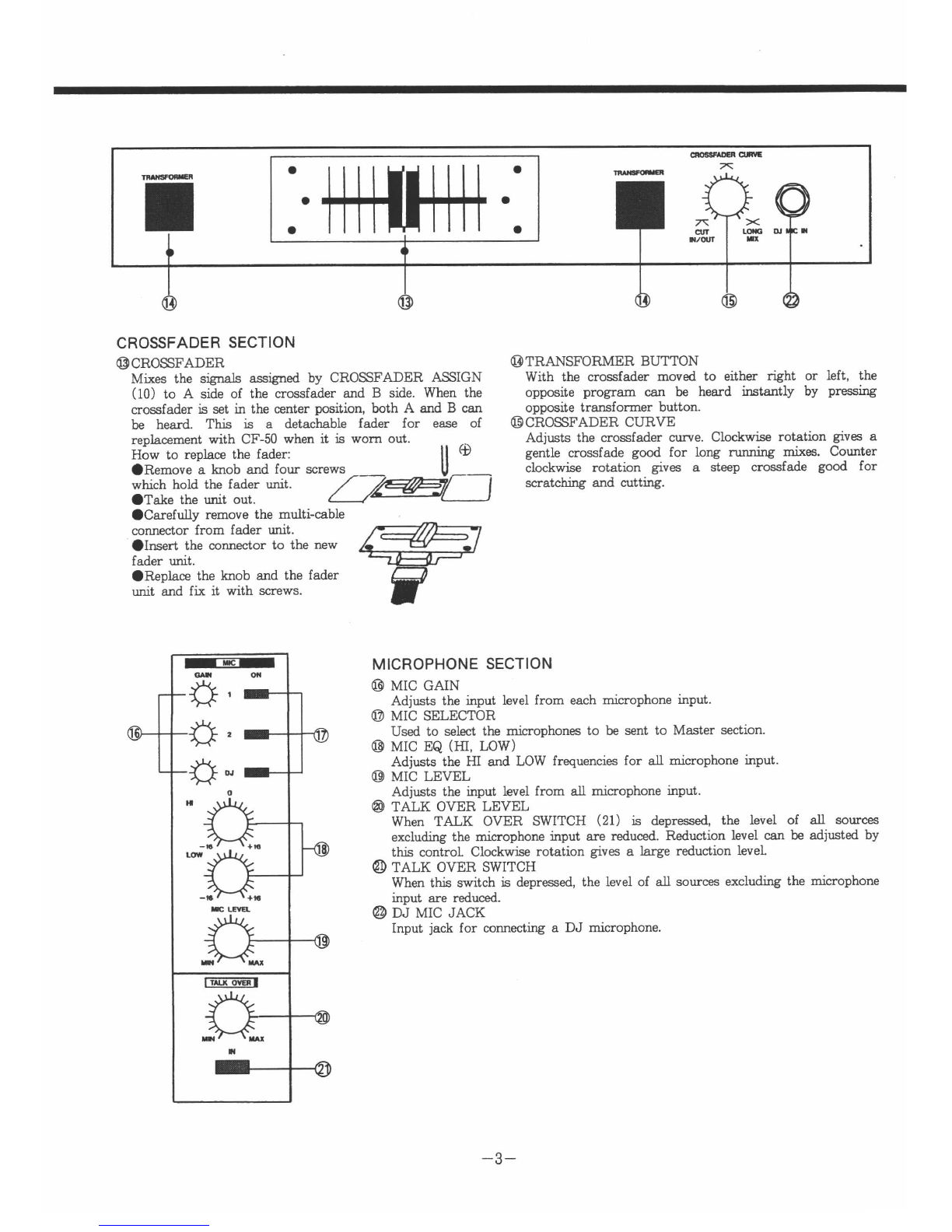
lnnovative features pioneered by VESTAX, such as User Replaceable Crossfader,
VCA crossfader operetion, Transformer Buttons and Crossfader Curve Adjustment
have been incorporated into a club mixer of highest grade. Top of the range, the
PMC-50 is high specification mixer designed to meet the most professional
requirements of Dance Music DJ's today. Please read this own€r's manual carefully
before you start to use your mixer, so that you will fully understand all of the
special fe€tures and €njoy the full us€ of the product.
FEATURES IMPORTANT
OA high specification VCA, Voltage Controlled
Amplifier, is utilized in the Crossfade system. This
minimizes noise and wear from the mechanical
Darts of the Crossfader. Additionallv' the
Crossfader "Curve" can be easily adjusted on the
front panel lor changes in Mixing styles. At one
extreme is the long running mix and at the other is
the Scratch or Cut mix.
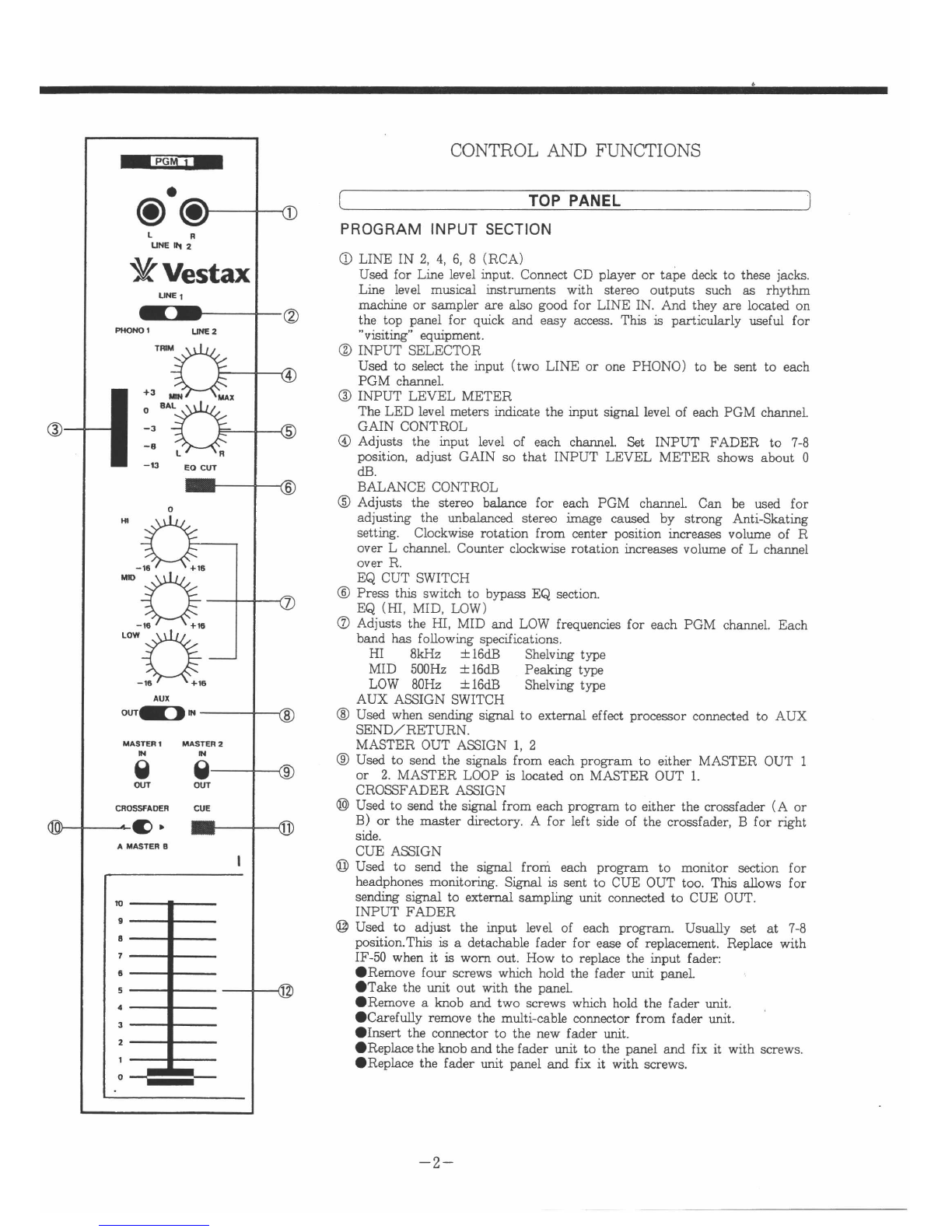
OEach of the input channels will accept one stereo
phono and two stereo line sources, these are
instantly switchable giving a massive twelve input
capability. Each input channel has a gain control
for the setting of input levels. A levei display,
balance control and three band EQ are also
orovided on each channel. The separate Mic input
section has its own EQ.
OOne stereo input of each channel can be connected
via the top panel for quick and easy access- This is
particularly useful for "visiting" DAT players, etc.
the stereo Insertion ports are provided on the front
Opanel. These allow for the easy connlction of
outboard effects such as VESTAX DCR-UO
Frequency Separator, Compressor and Gate
machines. And the stereo Master Loop is provided
on the top panel also. This allows for total sound
control with Graphic EQ or Reverberator, etc.
The PMC-50 has the most comprehensive output
Olineup as well. No less than two separate Masters
(balanced and unbalanced), one DJ Booth Monitor'
one stereo Cue and a Headphones Monitor makes
this mixer the most versatile "MIXER'S MIXER"
available today.
To prevent electric shock, do not remove cover. No user
serviceable parts inside. Refer servicing to qualified
personnel. Always disconnect all equipment from the main
supply when disconnecting,/reconnecting signal leads. The
power cord should be connected last. Make sure that the
power switch is off when connecting. Disconnect from AC
supply when equipment is not used for extended time.
WARRANTY
AUT10NS
Warranty might vary from country to country. Each
distributor has their own warranty system in
accordance with country or state regulations or laws.
VESTAX observes the manufacturing country's
regulations.
*Humidity and dust
Avoid use where there is high humidity and dust
which may cause damage to internal parts.
*Temperature
Avoid use in hot, (over 35t) and cold, (below 5C)
locations. Keep the unit away from extreme direct
heat such as direct sunlight, heating radiators, or
closed vehicles.
{:Power cord handling
Connecting the power cord to other cords -or -joining
cords togelher cLn cause fire and electric shock. This
is extremely dangerous.Take precaution when
handling AC plugs and connectors. Handle only- the
plug or connector and do not perform these operations
with wet hands.
*Keep away from liquids
Do not stand vessel containing liquids on or near the
equipment. If liquid enters equipment, disconnect the
pow-r cord from the power outlet immediately'
SPECIFiCAT!ONS
躙熙P血 Leveン h"dance ″
dBv/mkΩ
LINE ‐
10dBV/20kΩ
MIc ‐
60dBV/2kΩ
AIIX RTN ‑10dBV/10kn
MAttER L∞ P RTN ‑10dBV/10kΩ
PGM 1/O RTN ‐
10dBV/5kΩ
N憮 搬 電
瞭‰露響ごOdBv/.n
MASrER Otrr(BAL.) +4dBm/2000
AUX SEND ‐
10dBV/5000
CUE OUT
B00TH OUT
HEADPHON鵬
MASTER L∞ P SEND
PGM 1/O SEND
Frequency Response
S/N Ratio
THD
〕血ellsions(WXHXD)
Weight 7 0kg
Power Requlrement 20W
OdBV/5000
0dBV/500n
30mW max 0 330/≧ 80
‑10dBV/1k0
‑10dBV/5000
20Hz‑20kHz(+0,‑ldB)
≧
120dB
く0.01%Dhensions
330X90X400mm
‑1‑

…
VVestax
0 0
CONTROL AND FUN∝ IONS
t TOP PANEL 〕
PROGRAM:NPUT SECT10N
①LINE IN 2,4,6,8(RCA)
Used for Lhe level mput Connect CD player or tape deck to these iaCks
Lme level muslcal h誂 ―ents mth stereo outputs such as rhyth
machhe or sampler are also goOd fOr LINE IN.And they are located on
the top panel for quck and easy access Ths ls partlclllЯ rly useful for
"VISItmg"∞ u■pment
②ISIPUT SELECTOR
Used to select the hput(two LINE or one PHONO)to be sent to each
PGM chamel
③INPUT LEVEL METER
The LED level lneters ndlcate the mput 甲」leVe1 0f each PGM channel
GAIN CONTROL
④Adjusts the mput level of each channel Set INPUT FADER to 7‑8
pOslt10n,adiust GAIN so that INPUT LEVEL METER shows about 0
(1]3.
BALANCE CONTROL
⑤ AdiustS the stereo b』 mce fOr each PGM channelCan be used fOr
adiuSthg the lmbalanced stereo mage caused by strong AntISkathg
settng C10ckM71se rotatktt frOm center posltlon mcreases vol― e of R
over L channel Counter clockwlse rotatbn mcreases volume of L chamel
over R
EQ CUT SWITCH
⑥Press t逃 swich tO bypass EQ sectbn.
EQ(lΠ ,MID,LOW)
⑦AdiustS the HI,MID and LOW frequencles for each PCM charlnel Each
band has followlng speclftatlons
H1 8kHz ±
16dB She市 mg type
MID 51Xlttz ±16dB Peab鳴 type
LOW 80Hz ±16dB Shelvmg type
AUX ASSIGN SWITCH
③ Used when sendmg slgnal to extemal effect processor connected to AUX
SEND/RETttN.
MASTER OUT ASSIGN l,2
⑨Used to send the slgnals from each program to e■ her MASTER OUT l
or 2 MASTER LOOPお 10cated on MASTER OUT l
CROSFADER ASSIGN
⑩
蓄
■
t締乳まi瑠誡:諄lf篭 ざ駐盤
常糧讐肥
露
Tl」亀
踊
siie
CUE ASSIGN
⑪Used to send the sIMl fro五 each prOgram to mon■ tor s∝tlon for
headphones mOn■toHng SIgnal ls sent to CUE OUT too T陥 allows for
sendmg slnl tO exte―l sampLng ttt connected to CUE OUT.
INPUT FADER
⑫Used to adiuSt the Ⅲut leVe1 0f each program.Usua■ y set at 7‐ 8
posibn.Thお お a detachable fader for ease of repLcement. Replace with
IF― "when iお wOm Out.How to replace the hput fader:
●Remove four screws whch hold the fader u血 t paneL ,
●Take the―t Out、確th the paneL
●Remove a lmob and two screws whh hold the fader―t
●Carefuny relnove the multicabb connector frOm fader―t
●Insert the connector to the new fader unlt
●Replace the knob and the fader―t to the panel and f破 lt wlth screws
●Replace the fader umt panel and f破 i wth screws.
‑2‑

一■
CROSSFADER SECT10N
⑬CROSFADER
OOarefully remove the multi-cable
connector from fader urrit.
Olnsert the connector to the new
fader unit.
ORepl,ace the l:nob and the fader
unit and fix it with screws.
⑭TRANSFORMER BUTTON
M轟 the sIMIs ■
ped by CROSSFADER ASSIGN Wih the crossfader moved to either ttt
(10)tO A stt of the crossfader and B sme.when the opposie program can be 釘d墨 tantly
crossfader ls set h the center posib,both A and B can opposlte transfonner button.
be heard.Tb ls a detachable Fader for ease of ⑮CROSSFADER CURVE
隈 叫
軋ぃ
∝ け
ll
Ad,ustS the crossfader ctwe.Clock慟 轟rotath」veS a
gentle crossfade good for 10ng ―g ―eS・ COunter
clockwiЮ rotatlon glves a steep crossfade good for
matching and cutting.
MiCROPHONE SECT!ON
⑮MIC GAIN
AdiustS the Ⅲut bVel from each lrucrophone Ⅲut.
O MIC SELECTOR
Used to se闘 the― hones to be sent to Master sect■ on.
⑬MIC EQ(Ⅲ ,LOW)
AdiustS the lH and LOW frequencles for an面け。
phOne Ⅲut.
⑬MIC LEVEL
AdiustS the input level from an mlcrophone mput
④TALK OVER LEVEL
When TALK OVER SWITCH(21)お depressed,the level of an sOurces
excludmg t詭 ―
rOphone input are reduced.Reducth levd can adiustd by
this contrOI Cbё k宙∞rOtat■on glves a large reducth leveL
辺
)TALK OVER SWITCH
When ths swichお depressed,the level oF an sources excluぬ 嘔the ttphone
mput are reduced.
②D」 MIC JACK
Input]ack for colmα允
蛇aD」 mtrophone.
‑3‑

MASTER SECT10N
④POWER SWITCH
LED located on the top panelお ユwhen on.
a)MいSTER L∞P(RCA)
Ths loop rsend/retum)お located on MAヨ ER Olrr l
before output jack.Itお useFul for total sound control wih
Craphic EQ or Reverberator,etc.
C)OUTPUT LEVEL METER
The LIED level meters h出 颯te the sirl bVe1 0f MASTER
Om 10r2.
C)AUX SEND LEVEL
Used to adltt send levd from AUX SEITD The smお
selded by AUX ASSIGN SWITCH(8).
G)AUX RETITRN LEVEL
Used to鋼 ■
■retum level tO AUX RETURN.T陸 AUX
④
f馴翻
烏漁
usedお t詭 Sub line mp■ .
Select either MASrER OUT l or 2 mdicated by OUTPUT
LEVEL MrrER(25).
⑩L00P SWITCH
Used when s帥山喝 蜘 tO extemal efftt pr∝essor
comdedto MAMER L∞ P(24).
⑩MASTER OUT LEVEL l,2
Used to adJutt the output levd from MAS「ER OITr l and 2.
MONITOR SECTION
€)BOOTH MONTTOR MONORAT SWTTCH
When this switch is depressed, the output from BOOIH
OUT becomes monoral mi:r
@BOOTH MONITOR LEVEL
Used to adjust the output level from BOC/IH OL]T.
@ITEADPHONES MOMTOR SELECTOR
Select either CUE O(IT. MASTER OUT or AIIX SEND
for monitoring by headphones.
E)HEADPHONES LEVEL
Adjusts the headphones output level
@TmADPHONES JACK
When listening with stereo headphones, connect them to
thb jack. This features stereo cue system-
‑4‑

FRONT PANEL
⑩PROGRAM SEND/RETURN(RCA)
They are stereo chamel msertlon ports a■ ow for
the easy connectbn of outboard effects
REAR PANEL
│‐
‐G卜 ‐‐‐‐‐‐‐‐
l
α
)LINE IN l,3,5,7(RCA)
They work the same as LINE IN 2,4,6,8(1)
O PHONOIN l,2,3,4(RCA)
Connects t―table output equlpped wlth MM type
pおkup cartrldge.If MC type cartrldge is′ used,a pre
―p ls reqwed.
C)GROUND TERMINAL
Connects to ground lead of the t― table.Ttt helps
to reduce nolse and h― .
⑩MIC l,2(1/4"Phone)
Input iack fOr∞ nnectng the mcrophones.
①AIX SEND/RETlmN(1/4"Phone)
Conn∝ts to outbOard effects such as Delay macL .
AUX SEND Is located on prehput fader
⑫CtIE Om(1/4"Phone)
When CUE ASSIGN (11)ls depreSSed, the slgnal
comes out from this iack. It Can be used for samphng
source output.
O BOOTH OUT(1/4"Phone)
Tltt can be used for D」 booth monltor.Same slgnal
as HEADPHONES OUT comes out
④MASTER OUT l,2(1/4"Phone,Unbalanced)
Connects to the input of power F回 りrier.These iaCkS
are Phone type for consumer apphcations.Thも 面
has two pa曖 3 of MASTER OUT And each output
level can be set separately.Tl逃 means that MASTER
om can be used for mam output and sub.For
example, one for ha■ , the other for entrance.
MASTER OUT l,2(XLR,Balanced)
⑤Connects to the mput of power ampr● .These
connectors are XLR type for profeSSbnal a遇
apphcatbns.They work the same as Unbalanced
MASrER OUT l,2(44).Ph No3 for HOT.
AC POWER CABLE
⑮Connects the plug to AC outlet on the w己
◎OmOOmOOmOO
OO… ◎◎…
◎
◎…
0,0
‑5‑

﹁ 0 ︲一 0
● r 0 0 バ 0 一 >0 >
﹁ O Z O
L
﹁
r一 Zm r
F 一 Z同
一Oω
︵0﹂︶
︵020
︶
r
>CX
↓Z
rO 一0工一
ミ& 砲
>∽ 引 ﹇ 力 一 F﹇ < m r
躍
r
﹁L I
> ∽ ﹁ m
ゝ
塁
巡
遮
男
o
N 中 隔 ¨ 紳 ﹇﹁ュ 日
︲︲
日 ﹈ ︲
ヽ
︲ ヽい ︲ 4議 マ 輔
編凸 κ ぼ
rO 工一
ミ ゝ膏
鞣 酬サ よ ゲ
R R
T T
MA
S
MA
S
A
U
X
CU
E
﹂RL R L R﹂ R > ∽ ﹁ m 力 r O O ﹁
∽﹇ 20 0<
r r
r OO﹁∽ g ヽ
CHm∽Sヽ
磋
F
︻﹁T.一 ¨∽ ﹁ m
"「
>∽引口rm●
亀
カ
O Z一 ﹁ 0 F
∞OOH工rmく﹇r
OZ一■ 0
工O r﹁くmr
‑6‑

VHAX CORPORAT10N SEP1995 PMC50E V l
Table of contents
Other Vestax Dj Equipment manuals

Vestax
Vestax PMC-280 User manual

Vestax
Vestax Typhoon User manual

Vestax
Vestax Typhoon User manual

Vestax
Vestax DGE-X2 User manual

Vestax
Vestax SPIN User manual

Vestax
Vestax PMC-15SL User manual

Vestax
Vestax Vestax VCI-380 User manual

Vestax
Vestax DWG-X1 User manual

Vestax
Vestax PMC-05Pro User manual

Vestax
Vestax DCR-1200 Pro User manual

Vestax
Vestax DCR-1500 User manual

Vestax
Vestax PMC-06ProA User manual

Vestax
Vestax DCR-1200 User manual

Vestax
Vestax TR-1 User manual

Vestax
Vestax PMC-400 User manual

Vestax
Vestax VFX-1 User manual

Vestax
Vestax VCI-400 User manual

Vestax
Vestax FDG-1 User manual

Vestax
Vestax Typhoon User manual

Vestax
Vestax Typhoon User manual