VESTEL BLDC Pyrojet Series User manual

Service Manual
for
BLDC Pyrojet Series

Prapared by Customer Technical Supoort Department in Vestel Washing Machine Plant –Manisa –Turkey
Page 2
Table of Contents
1. Safety Precautions ........................................................................................................................................................ 4
2. Specifications ................................................................................................................................................................ 5
3. Assambly Information................................................................................................................................................... 5
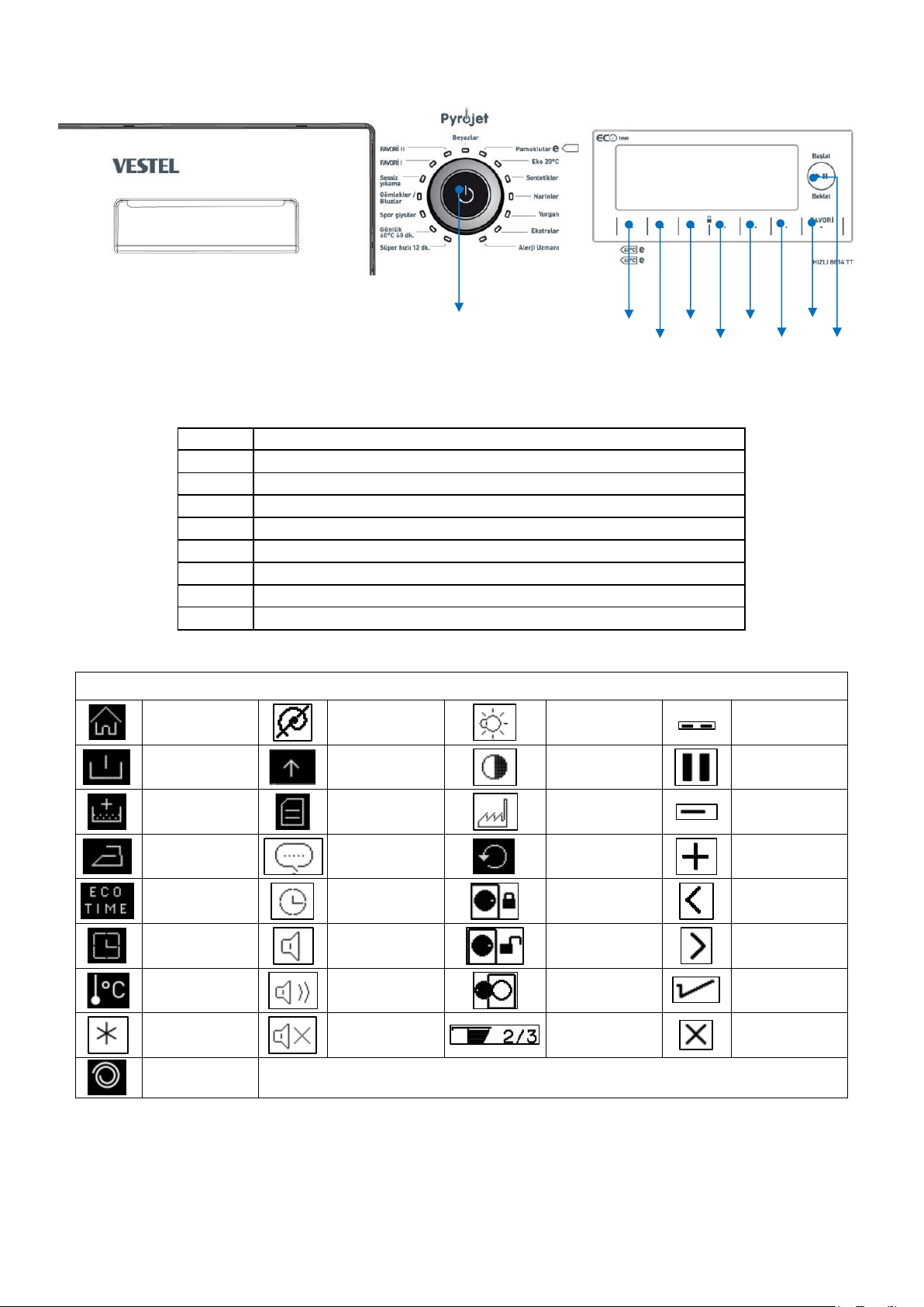
4. Control Panel and Acronyms......................................................................................................................................... 7
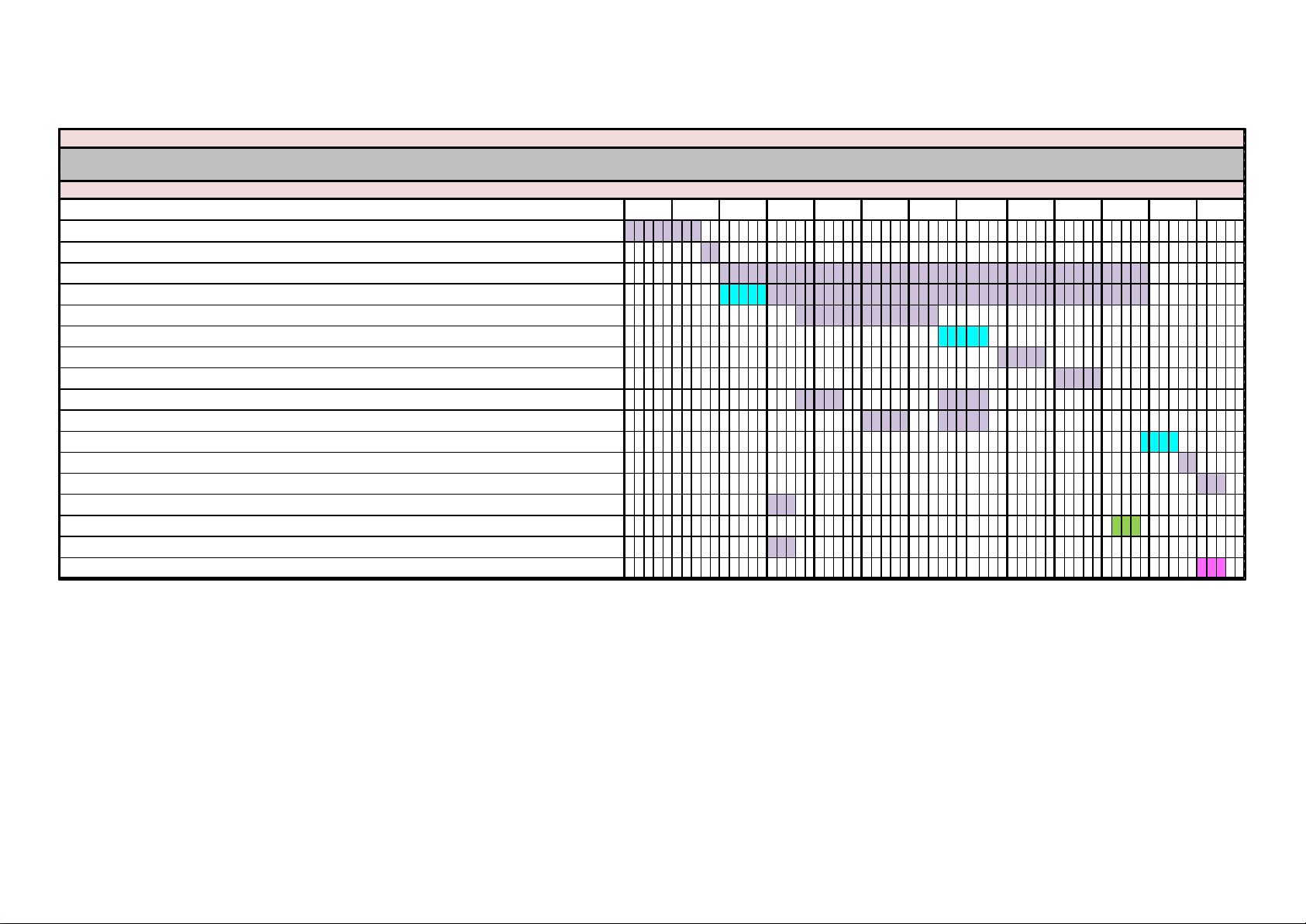
5. Test Mode ..................................................................................................................................................................... 8
5.1. Autotest.................................................................................................................................................................................. 8
5.2. Program Parameters .............................................................................................................................................................. 8
6. Service Mode .............................................................................................................................................................. 10
6.1. Service Autotest .................................................................................................................................................................... 10
6.2. Failure Codes ......................................................................................................................................................................... 11
7. Critical Torque Values ................................................................................................................................................. 11
8. Disassembly and Assembly Instructions .....................................................................................................................12
8.1. Top Plate ............................................................................................................................................................................... 12
8.2. Door....................................................................................................................................................................................... 12
8.3. Spring Wire............................................................................................................................................................................ 13
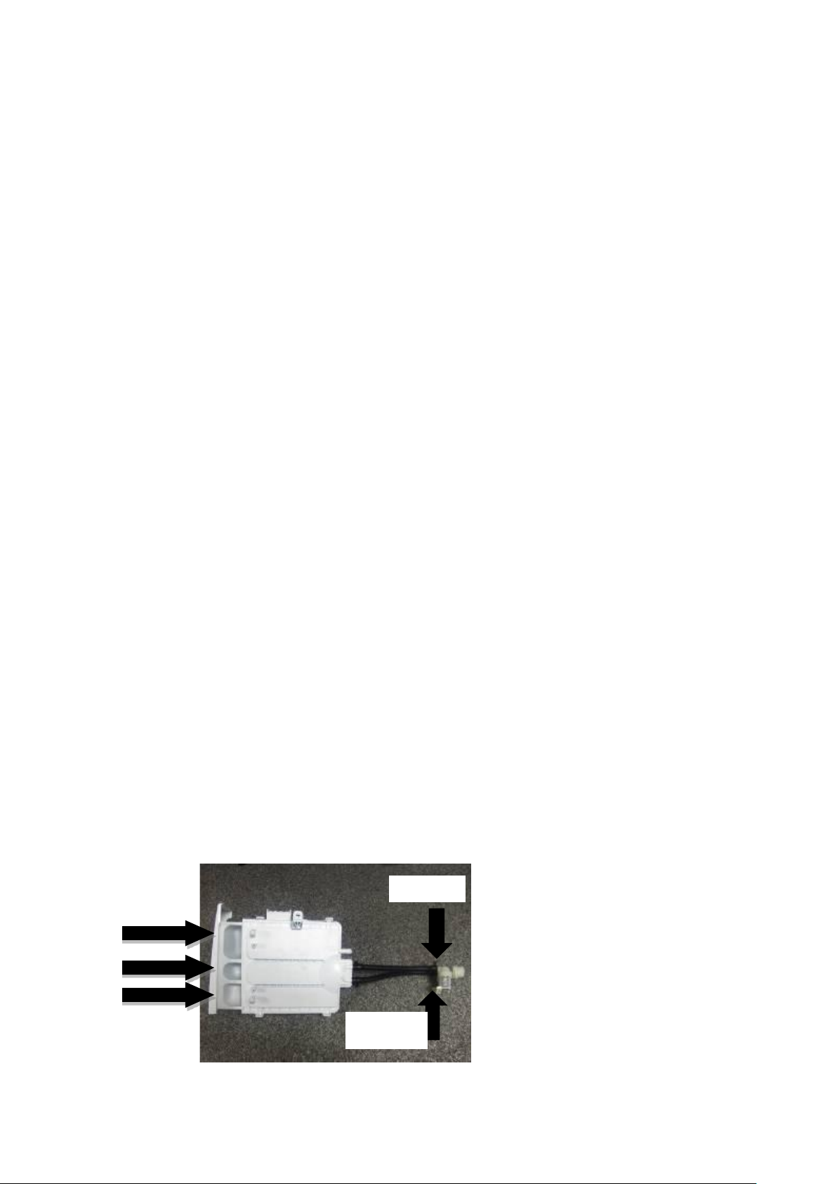
8.4. Detergent Drawer ................................................................................................................................................................. 13
8.5. Control Panel......................................................................................................................................................................... 13
8.6. Electronic Card & Fuse .......................................................................................................................................................... 14
8.7. Front Panel ............................................................................................................................................................................ 15
8.8. Support Bracket..................................................................................................................................................................... 16
8.9. Detergent Drawer Housing ................................................................................................................................................... 16
8.10. Power Cable Group and EMI Filter ...................................................................................................................................... 17
8.11. Electronic Pressure Switch (EPS) ......................................................................................................................................... 17
8.12. Door Lock* .......................................................................................................................................................................... 18
8.13. Pyrojet Card......................................................................................................................................................................... 18
8.14. Drain Pump.......................................................................................................................................................................... 18
8.15. Front Counterweight* ......................................................................................................................................................... 18
8.16. Heater.................................................................................................................................................................................. 19
8.17. Pyrojet System .................................................................................................................................................................... 19
8.18. Twinjet System* .................................................................................................................................................................. 20
8.19. Tub Bellow Seal* ................................................................................................................................................................. 21
8.20. Transport Screw .................................................................................................................................................................. 21
8.21. Upper Counterweight*........................................................................................................................................................ 21
8.22. Washing Group.................................................................................................................................................................... 22
8.23. Shock Absorber Pin ............................................................................................................................................................. 22
8.24. Driven Pulley ....................................................................................................................................................................... 22
8.25. Driven Pulley ....................................................................................................................................................................... 22
8.26. Motor .................................................................................................................................................................................. 23
8.27. Tub ...................................................................................................................................................................................... 23
8.28. BLDC card ............................................................................................................................................................................ 23
9. Component Specifications .......................................................................................................................................... 26
9.1. Drain Pump............................................................................................................................................................................ 26
9.2. Circulation Pump* ................................................................................................................................................................. 27
9.3. Heater.................................................................................................................................................................................... 28
9.4. NTC ........................................................................................................................................................................................ 29
9.5. Valve...................................................................................................................................................................................... 30
9.6. Electronic Pressure Sensor (EPS)* ......................................................................................................................................... 31
9.7. Motor .................................................................................................................................................................................... 32
9.8. Door Lock* ............................................................................................................................................................................ 33
9.9. Pyrojet* ................................................................................................................................................................................. 34
10. Wiring Diagram* ....................................................................................................................................................... 35

Prapared by Customer Technical Supoort Department in Vestel Washing Machine Plant –Manisa –Turkey
Page 3
About Content
This service bulletin is prepared for all OEM products within FG range. Therefore you may encounter information
about some optional components that may not exist in your product. As this is a generic service bulletin covering all
range, please ignore and skip extra/optional component information. Sections marked with asterisk (*) sign contain
information about optional components.
Information already exists in user manuals is not included in this service manual. Please refer to user manual of your
product for basic installation, operating, maintenance and troubleshooting issues.
Contact
For your inquiries please send an email to:
WashingMachineCustomerSupp[email protected]
You can also open a support ticket using Service Support Page:
https://www.vestelservice.com/VestelService/
Acronyms:
WM : Washing Machine
WMCS : Washing Machine Customer Support
TJ : Twinjet
UI : User Interface
SI : Service Interface
A : Available
NA : Not Available

Prapared by Customer Technical Supoort Department in Vestel Washing Machine Plant –Manisa –Turkey
Page 4
1. Safety Precautions
Important:
This service information is designed for experienced repair technicians only and is not designed
for use by the general public. It does not contain warnings or cautions to advise non-technical
individuals of potential dangers in attempting to service a product. Products powered by
electricity should be serviced or repaired only by experienced professional technicians. Any
attempt to service or repair the product or products dealt with in this service information by
anyone else could result in serious injury or death.
Warning:
Before any disassembly/repair operation make sure appliance is unlplugged water tap is closed
and heating elements are cooled down. There is electrical shock, burning and flood risk.
Warning:
Please replace whole cable group even in case there is any minor failure with cables / terminals /
sockets. Never try to repair nor to solder cable group. It may cause smoke, ignition and there is
major risk of electrical shock.
Important:
Always use insulator gloves to prevent injury by metal edges or to prevent electrical shock during
electrical tests.
Work with uniforms having long sleeves to protect your arms from metal edges.
Always use original spare parts. You may harm appliance, end user, environment or yourself
using untested and unapproved 3rd party spare parts.
Use right tools to prevent any wear or damage to components during assembly/disassembly.

Prapared by Customer Technical Supoort Department in Vestel Washing Machine Plant –Manisa –Turkey
Page 5
2. Specifications
Here you will find descriptions of generic specifications for the range specified for this service manual. Please refer to
product fiche and user manual for detailed technical specifications.
*Twinjet System:
Twinjet system is designed to obtain a better washing performance by directly injecting water
with detergent using a recirculation system and two nozzles connected to it. With twinjet
system, water consumption is decreased by 30%, energy consumption is decreased by 10% and
washing time is decreased by 15%
Twinjet system is valid for all programs except spin and drain mode. The system dos not function
during Water inlet, heating, spinning, drain phases.
Even with a large load of 8 kg. the washing machine will have the minimum energy consumption
by the help of Twinjet system.
Washing machines with Twinjet system are very environment-friendly by having maximum
washing performance with minimum water consumption.
Eco-Logic System:
Half load detection system, thus using less water and power accordingly. This system is available
for cotton programs only.
Foam Protection System:
Foam Protection System is a safety algorithm that interrupts normal program flow and reduces
foam level by taking water and draining. This algorithm protects machine and environment
avoiding over foaming inside tub in case any customer misuse such as detergent overdose or use
of foamy cleaning agents.
Overflow Protection System:
Overflow protection is another safety algorithm in case of a flood risk. If there is more water in
tub than expected by algorithm, it will start to the drain routine giving E04 failure code. For
example this may happen in case of a valve failure and the machine constantly takes water. This
algorithm will keep drain routine, keeps water leveled and protects environment and machine
avoiding any flood risk.
Unbalanced Load Detection and Control System:
Unbalance Control System is another safety algorithm that protects the machine and
environment avoiding machine movement due to vibration during spinning profile. The
algorithm tries to balance load by a special balancing agitation, postponing spin profile till it is
balanced. This avoids spinning while load is unbalanced and prevents any possible physical harm
both to the appliance and to surroundings.

Prapared by Customer Technical Supoort Department in Vestel Washing Machine Plant –Manisa –Turkey
Page 6
3. Assembly Information.
3.1. The Customers need to be informed about the below subjects.
1. General information about the product. (General features, class of energy and RPM etc.)
2. Classification of the laundry depends on the color, type and feature.
3. Selecting the particular program for the laundry and using the detergent and softener.
4. Using the knob of the temperature and RPM and settings
5. The information about the volume of the dry laundry that could be washed one at a time,
6. Information about the additional functions
7. Requirements in order to start a program (step by step)
8. How to put a program on hold
9. How to cancel a program
10. Activation and deactivation of the child lock. In addition it needs to be clarified that, child lock does not
deactivated by itself at the end of the program.
11. Information about the half load detection and its effect to programs.
12. Information about the control of the unbalance load distribution and machine behavior with unbalanced load
during the spin cycle.
13. Information about the door lock. (Door lock deactivation takes place after 2 min when program ends, or after 2
minutes, when end light is flash and during the empting process in program.)
14. Please advise customer to read the user manual and firstly see the relevant section when possible fault occurs.
15. Information about the adjustment of the feet in case of replacement of machine,
16. Information about using and cleaning the detergent drawer group,
17. Information about necessary cleaning period of the drain pump, drain hose and filter, water entry valve.
18. The information about the drain hose location.
19. The information about proper condition of the water entry and drain. Please advise the customer to make sure
the hoses are not bended or twisted and please warn the customer not to use additional hose part.
20. Information about the situation that observing few water inside the drum during the washing cycle, is normal.
21. Information about keeping the transformation screws and assembling on the machine whenever the machine
needs to be replaced.
Please advise the customer to read the user manual and firstly see the relevant section when and possible fault
occurs.
To do list:
1. Please check the environmental conditions. (Water pressure, voltage, current, ground, electrical installation,
plumbing)
2. Make sure the product is used properly. (Child lock deactivation. Etc.)
3. Use the autotest program to test the machine.
4. If system shows any faulty code, find the particular code on the error list and take and action according to it.
5. Check the electrical connections.
6. Make sure the cable and hose connections are regular.
Main wash
Softener
Prewash
Valve 1
Valve 2
Prewash = Water enters from Valve 1
Main Wash = Water enters from Valve 2
Softener = Water enters from Valve 1 and 2

Prapared by Customer Technical Supoort Department in Vestel Washing Machine Plant –Manisa –Turkey
Page 7
4. Control Panel and Acronyms
PR
Program selector 16 programs including off position
SW1
Switch 1, Start / Pause
SW2
Switch 2, Memory
SW3
Switch 3, Other Options / Delay Start
SW4
Switch 4, Settings / Eco Time Option
SW5
Switch 5, Stain Level Selection / Easy Ironing Option
SW6
Switch 6, Stain Type Selection / Extra Rinse & Anti Allergic Option
SW7
Switch 7, Spin Speed Selection / Prewash Option
SW8
Switch 8, Temperature Selection / Previous Options
Symbols
Selection Mode
No Spin
Brightness
No Selection
Prewash
Other Options
Contrast
Pause
Extra Rinse –
Allergy Safe
Settings
Factory Settings
Decrease
Selection
Easy Ironing
Language
Reset
Increase
Selection
Eco Time
Clock
Door Closed and
Locked
Previous
Selection
Delay Start
Sound
Door Closed and
Unlocked
Next Selection
Temperature
Sound On
Door Open
Select
Cold Wash
Sound Off
Dosage Indıcator
Cancel
Spin Speed
SW8
SW7
SW6
SW5
SW4
SW3
SW2
PR
SW1

Prapared by Customer Technical Supoort Department in Vestel Washing Machine Plant –Manisa –Turkey
Page 8
5. Test Mode
5.1. Autotest
5.1.1. Autotest Steps
1. Open SI by pressing SW4 for 5 seconds.
Autotest follows a predefined flowchart in order. Unlike
service autotest, autotest automatically skips to next step
upon completing one. The steps of the test are as follows:
Step1:
Drain pump is activated.
EPS frequency is checked.
Step2:
Motor ramps to max spin.
Prewash & Wash valves are activated in order.
Step3:
Motor ramps down to stop.
Prewash & Wash valves are activated simultaneously.
Step4:
Motor turns clockwise (low speed).
Step5:
Motor turns counterclockwise (low speed).
Step6:
Twinjet is activated.
Step7:
Prewash & Wash valves are activated simultaneously.
Step8:
Washer heater is activated. Washer NTC values are
checked in this step.
In case of no failure test ends after this step and “End” is
displayed. In case of an error detection EXX and error
definition will pop up on display. (where XX is the error
number 1 to 10 )
Please see following autotest chart for details.
1. 2. Press button below “AU” indication which stands
for Autotest.
2.
3. When autotest is finished, END screen is
visualized.
5.2 Program Parameters
When the SW2 ‘’memory’’ button is pressed as long as 10
seconds at any moment, The parameters of the program
occus on the display:
Temperature
Voltage
RPM
HZ value which EPS’ detects.
In order to see the normal screen please press the same
button as long as 10 seconds again.
If the SW4 button is pressed as long as 10 seconds during
The service mode, counter will appear.
Counter shows the program detail which program knob
Set on at the moment.
coton
Service mode

Prapared by Customer Technical Supoort Department in Vestel Washing Machine Plant –Manisa –Turkey
Page 9
Time in seconds (to be adjusted)
Entering autotest
Changing power to 220 50Hz
Main Voltage 50 Hz
Door Lock Powered (Depends on door lock)
Motor Ramp to max spin (max. is 15 sec.)
Time until motor is stopped (Depends on the motor stop time)
Motor Preferred Run (Direction to Right)
Motor Inverse Run (Direction to Left)
EV1 (flowrate dependent of washer)
EV2 (flowrate dependent of washer)
EV1 + EV2 valves up to first level frequency (Depends on the water level)
NTC check
Heather resistance
Pump
Twinjet activation
EPS measurement
End Visualization (On Display)
50
55
60
65
30
35
40
45
5
10
15
25
20
AUTOTEST

Prapared by Customer Technical Supoort Department in Vestel Washing Machine Plant –Manisa –Turkey
Page 10
6. Service Mode
6.1. Service Autotest
5.1.1. Service Autotest Steps
1. Open SI by pressing SW4 for 5 seconds.
If you turn knob position to other program between 1st to
3rd it will skip current test and start the selected one. It is
recommended not to skip any steps for a detailed
checkup. Unlike autotest, service autotest starts next test
step manually by rotating program selection knob.
Step1:
There will be a certain amount of water intake and then
washer heater is activated for 8 minutes. Washer NTC
values are checked in this period. In case of a washer
heater/NTC failure, it pops up E05 error displaying “E05”
on SW3.
In case of no failure at the end of heating step, “Please
change selector” will be displayed. You can turn program
knob to 2nd position to continue with step2.
*During this step if EPS detects high water level, overflow
algorithm is applied and E04 is released.
*If user changes the selector position, machine will do
what is defined for the new selected position.
Step2:
Drain pump is activated; in case of a pump failure it pops
up E03 error.
At the end of pump activation, “Please
change selector” will be displayed. You can turn program
knob to 3rd position to continue with step3.
Step3:
Rapid 12’*(15’ for non-TJ models) program algorithms is
run testing all washing components, the only difference is
error codes are displayed on SW3 which normally are not
displayed to end user.
If case of no error service autotest ends and "End" is
displayed.
3. 2. Press button below “SAU” indication which stands
for Service Autotest.
3. When autotest is finished, END screen is
visualized.
Step1
Step 2
Step 3
PR Position:
Program 1
PR Position:
Program 2
PR Position:
Program 3
HEATER ON
PUMP ON
TEST PROGRAM
ON (Rapid 12’*)
Comments :
When
entering in
service test,
door will be
locked.
Test is over
Door will be
unlocked,
machine will go
to END state.

Prapared by Customer Technical Supoort Department in Vestel Washing Machine Plant –Manisa –Turkey
Page 11
6.2. Failure Codes
Error Indication
Error Number
Indication in UI
Indication in SI
Door Lock Error
E01
A
A
Lack of water
E02
A
A
Pump failure
E03
A
A
Overflow
E04
A
A
NTC or Heater Failure
E05
NA
A
Motor Failure
E06
NA
A
Voltage
E09
NA
A
Electronic Pressure Sensor
E10
NA
A
Flowmeter
E17
NA
A
Motor (BLDC)
E19
NA
A
Pyrojet
E20
NA
A
7. Critical Torque Values
Assembly Locatıon
Bolt/Nut
Torque
Min. (Nm)
Torque
Nom. (Nm)
Torque
Max.
(Nm)
Air Pressure
Wrench
(rpm)
*
Transport Screw Assembly
Transport Screws
6.50
6.50
7.00
1000
*
Motor Assembly
Motor Screws
6.00
6.50
7.50
800
*
Front Concrete Weight - Front
Tub Assembly
Front Counterweight
Screws
14.00
14.50
14.75
600
*
Upper Counter Weight
Assembly
Upper Counterweight
Screws
25.00
27.50
30.00
440
*
Pulley –Drive Shaft –
Washing Group Assembly
Pulley –Drive Shaft
Assembly Bolt
39.50
40.00
40.50
440
*
Heater Assembly
Heater Assembly Nut
3.85
4.00
4.00
970
The bolts/nuts above are important for product safety purposes. Please tighten screw, bolts and nuts
according to the torque values given in table above.

Prapared by Customer Technical Supoort Department in Vestel Washing Machine Plant –Manisa –Turkey
Page 12
8. Disassembly and Assembly Instructions
8.1. Top Plate
1
2
Remove two screws that fix the top-plate at
the back.
Push the top-plate back and pull it up.
8.2. Door
1
2
Remove two screws that fix the door. (by
using T25 tool)
Pull the door up.
3
4
Remove screws that fix the door group.
Put the door outside plastic with helping
screwdriver.
5
6
Remove the door inside plastic.
Remove six screws that fix the door hinge.
T25

Prapared by Customer Technical Supoort Department in Vestel Washing Machine Plant –Manisa –Turkey
Page 13
7*
8*
Remove the door handle.
Remove the door handle pin.
8.3. Spring Wire
1
2
First remove the spring wire fixing the tub
bellows seal by using the small size screw
driver. Pull the tub bellows seal.
Remove the tub bellows seal-body fixing
spring.
8.4. Detergent Drawer
1
2
Gently pull the detergent drawer.
While pressing siphon cover keep pulling
drawer to remove it.
8.5. Control Panel
1
2
Remove the screw which fixes the control
panel to the front panel.
Remove two screws fixing control panel.

Prapared by Customer Technical Supoort Department in Vestel Washing Machine Plant –Manisa –Turkey
Page 14
3
4
Pull the control panel out
Remove socket connectors and remove the
LCD connector.
5
6
1) Remove the screw that fix PCB box
2) Remove the clips by using the screw
driver as shown image.
Remove the PCB box from the Control Panel
7
8
Remove the Lightguide cover by pressing the clip
that fixes it.
Remove the lightguide by pressing the clip
that fixes it.
8.6. Electronic Card & Fuse
1
2
Remove PCB box using a small screw driver
Remove the clip fixing the cover.

Prapared by Customer Technical Supoort Department in Vestel Washing Machine Plant –Manisa –Turkey
Page 15
8.7. Front Panel
1
2
Remove the screw under the pomp cover
Remove the emergency open pull
3
4
Remove the pomp inside cover by pressing
the clip
Remove the screw fixing the front panel at
the bottom
5
6
Remove the screws fixing the door lock
remove the door lock by pressing.
Remove the tub bellows seal.
7
8
Remove two screws fixing front panel to
body
Remove the screw fixing twinjet elbow

Prapared by Customer Technical Supoort Department in Vestel Washing Machine Plant –Manisa –Turkey
Page 16
9
10
Pull front panel up
Remove front panel
8.8. Support Bracket
1
2
Remove two screws fixing the body group on
the upper part
Remove two clips fixing detergent drawer
housing to upper support bracket
8.9. Detergent Drawer Housing
1
2
Remove the tub bellow hose by releasing the
holder extensions of bellow hose
Unplug connectors from feed valve
3
4
Slightly turn the feed valve counter-
clockwise to remove
Remove the detergent drawer housing
assembly

Prapared by Customer Technical Supoort Department in Vestel Washing Machine Plant –Manisa –Turkey
Page 17
8.10. Power Cable Group and EMI Filter
1
2
Remove the five connectors that is
connected to the EMI filter
Remove two screws fixing EMI filter.
3
4
Pull the power cable group up
Remove EMI filter
8.11. Electronic Pressure Switch (EPS)
1
2
Unplug EPS connector
Pull EPS up
3
Remove clamp from EPS hose

Prapared by Customer Technical Supoort Department in Vestel Washing Machine Plant –Manisa –Turkey
Page 18
8.12. Door Lock*
8.13. Pyrojet Card
1
2
Unplug door lock connector
Remove the screws fixing the card. Remove
the connections and remove the card as a
last step
8.14. Drain Pump
1
2
Remove clamp holding drain hose by using a
nipper.
Unplug drain pump connector
3
4
Remove screws holding drain pump
Remove the pump entrance hose and pyrojet
hose by using the nippers
8.15. Front Counterweight*
1
2
Remove three screws on the front
counterweight. (Wrench size 13 mm)
Gently pull counterweight out

Prapared by Customer Technical Supoort Department in Vestel Washing Machine Plant –Manisa –Turkey
Page 19
8.16. Heater
1
2
Unplug heater connectors
Remove nut (8 mm) fixing the heater
3
Pull heater out gently holding both sides.
8.17. Pyrojet System
1
2
Remove the screws that fix the pyrojet unit
Remove the protective foil if replacement
available if not bend it to the other side.
3
4
Remove the pyrojet unit by pulling upwards.
Remove the conncetions.

Prapared by Customer Technical Supoort Department in Vestel Washing Machine Plant –Manisa –Turkey
Page 20
5
6
Remove the clap that fixies the hose by using
the nipper
Remove the socket that belongs to Pyrojet
and remove the pyrojet.
8.18. Twinjet System*
1
2
Remove twinjet hoses from tub bellow seal
pulling them up
Remove the tub gasket clip by using small
screwdriver
3
4
Remove the cover that placed under the
machine by removing the screws
Remove screw fixing circulation pump
5
6
Lay the appliance down and press on ratchet
holding circulation pump
Remove circulation pump
Table of contents
Other VESTEL Dishwasher manuals

VESTEL
VESTEL LCD Series User manual

VESTEL
VESTEL ANGELO FNAC11 Manual

VESTEL
VESTEL BMH-XL 608 X User manual

VESTEL
VESTEL NOVUS Series User manual

VESTEL
VESTEL DW 5003 User manual

VESTEL
VESTEL A Series User manual

VESTEL
VESTEL BMH-L406 W User manual

VESTEL
VESTEL BMA-407 I User manual

VESTEL
VESTEL BMJ-L501 X User manual

VESTEL
VESTEL DW 5006 User manual

VESTEL
VESTEL DW 5006 User manual

VESTEL
VESTEL DW 5003 User manual

VESTEL
VESTEL S-E0440 User manual

VESTEL
VESTEL BMH-M301 S User manual

VESTEL
VESTEL I Series User manual

VESTEL
VESTEL Dishwasher User manual

VESTEL
VESTEL S-D0460 User manual

VESTEL
VESTEL BMH-L401 W User manual

VESTEL
VESTEL DL Series User manual

VESTEL
VESTEL ABX-402 E User manual