Vetek DGT User manual

WEIGHT INDICATORS
DGT/DGT60/DGTQ
and
DGTP
Technical Manual
DGT_DGT60_DGTQ_DGTP_06.01_09.11_EN_T

DGT DGT60 DGTQ DGTP
2
INDEX
1. REQUIREMENTS FOR AN EFFECTIVE INSTALLATION ...................................................................................... 3
2. CONNECTION TO THE LOAD RECEIVER............................................................................................................. 4
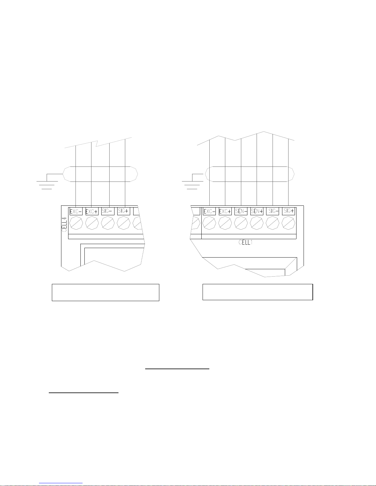
2.1 DGT and DGT60 Models .................................................................................................................................... 4
2.2 DGTQ Model....................................................................................................................................................... 5
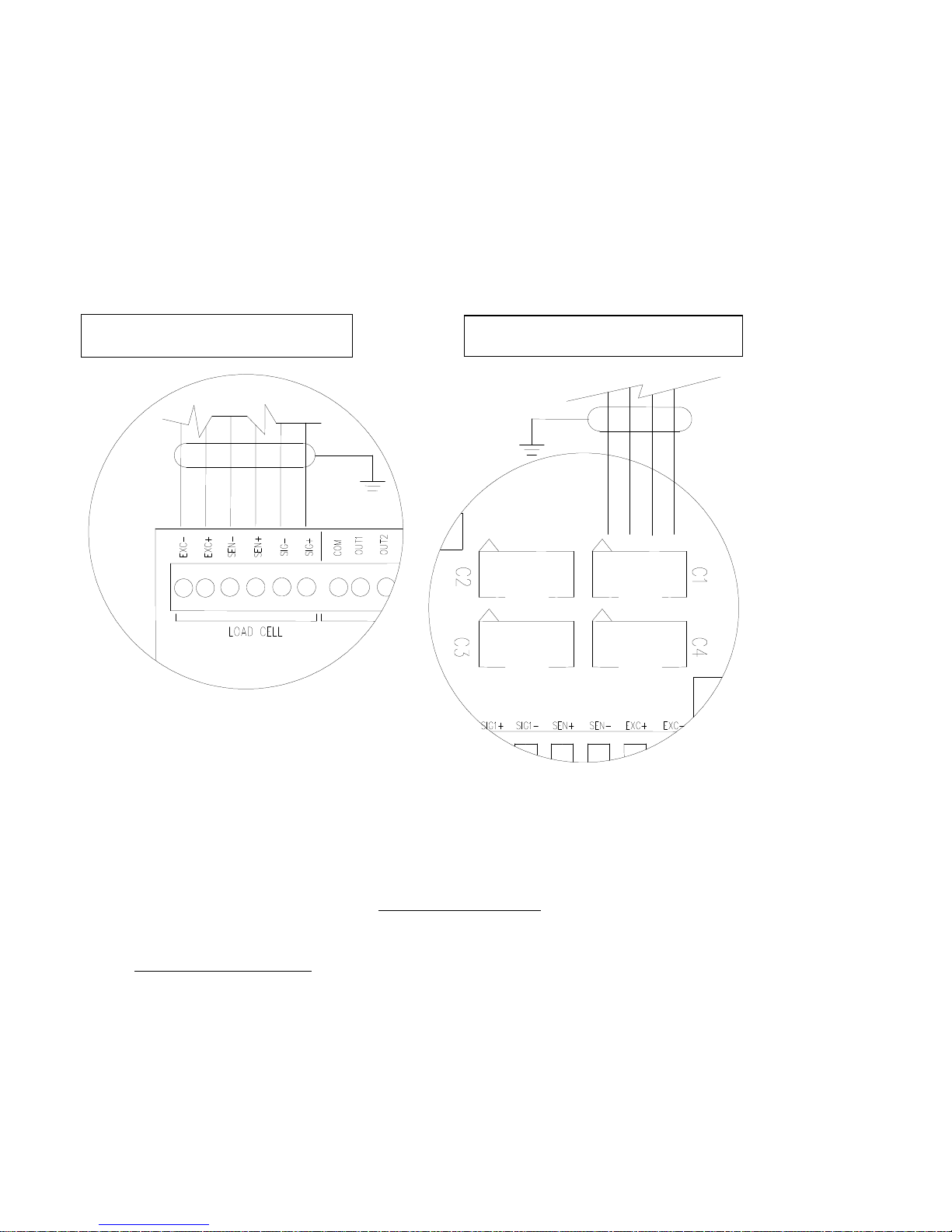
2.3 DGTP Model...................................................................................................................................................... 6
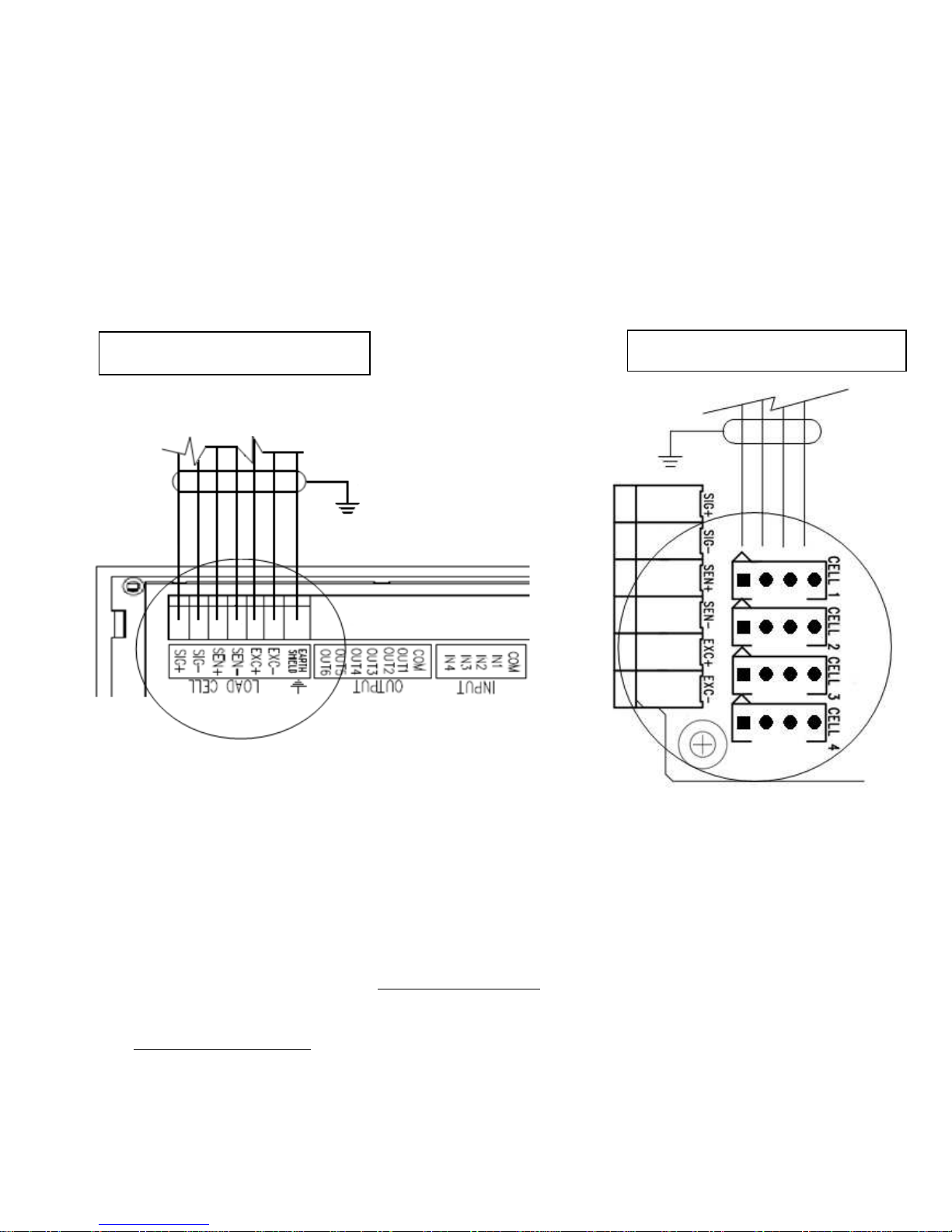
2.4 EARTHING SYSTEM......................................................................................................................................... 7
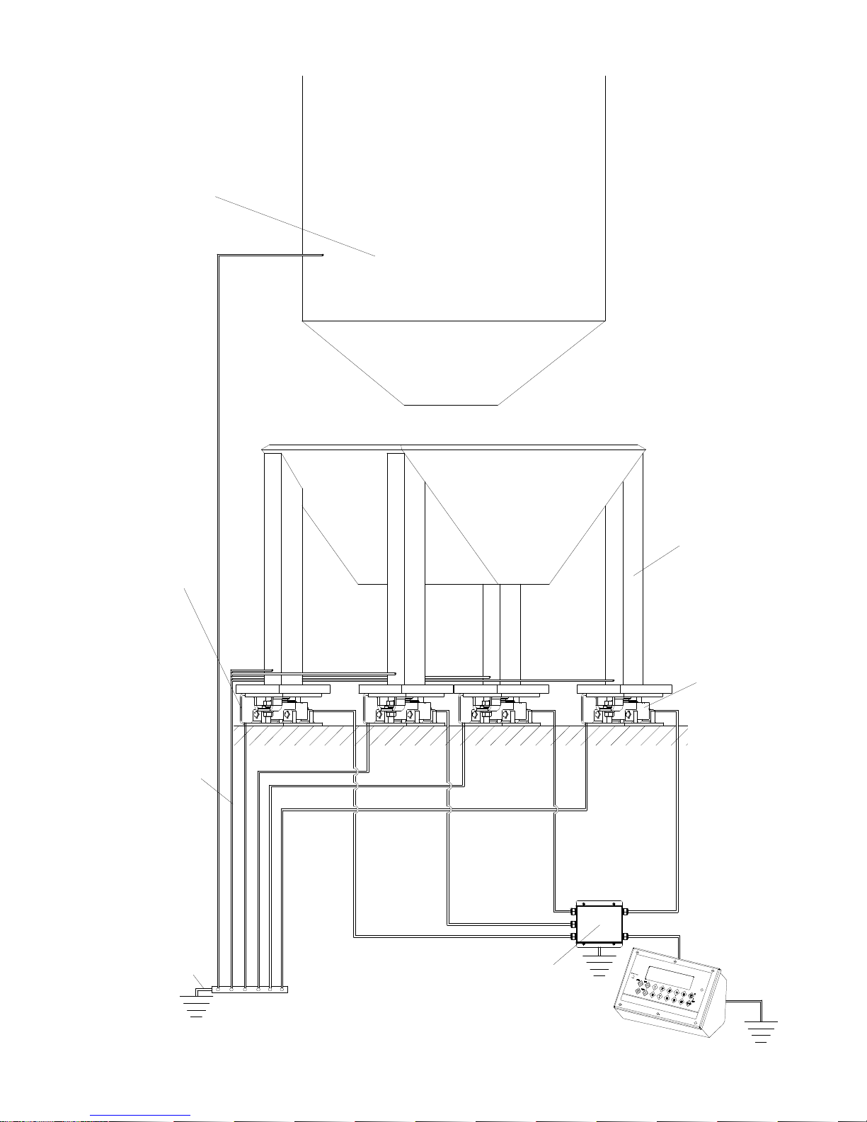
3. SETUP ENVIRONMENT .......................................................................................................................................... 9
3.1 SET UP ENVIRONMENT BLOCK DIAGRAM................................................................................................... 10
3.2 DESCRIPTION OF THE STEPS....................................................................................................................... 13
4. CALIBRATION....................................................................................................................................................... 26
4.1 Calibration procedure for the INDEPENDENT CHANNELS and "TRANSM" MODE ........................................ 26
4.2 Calibration procedure for DEPENDENT CHANNELS MODE (could eventually be digitally equalized) ............ 28
4.3 IN CASE THE ZONE OF USE IS DIFFERENT FROM THE CALIBRATION ZONE ONE SHOULD:................ 29
4.4 QUICK CALIBRATION OF ZERO..................................................................................................................... 30
4.5 THEORETICAL CALIBRATION........................................................................................................................ 30
5. GRAVITY ACCELERATION AND CORRECTION OF THE WEIGHING ERROR. ................................................ 31
5.1 INDICATION OF THE GRAVITY ACCELERATION VALUE............................................................................. 31
5.2 CORRECTION OF THE WEIGHING ERROR introduced by a different g value between the calibration and
utilisation zone (compulsory for legal type instruments).......................................................................................... 31
6. SERIAL OUTPUTS ................................................................................................................................................ 31
6.1 RS485 (DGT4 / DGT60 / DGT4 AN) or COM1 (DGTQ / DGTQ AN/ DGTP / DGTP AN) SERIAL PORT ......... 31
6.2 RS232 or COM2 SERIAL PORT....................................................................................................................... 33
6.3 PROFIBUS PORT (DGT4PB, DGTQPB and DGTPPB version)....................................................................... 34
6.4 SERIAL PORT TRANSMISSION MODES........................................................................................................ 34
6.4.1 PC PORT SELECTION.............................................................................................................................. 34
6.4.2 PC PORT ................................................................................................................................................... 35
6.4.3 PRN PORT................................................................................................................................................. 37
6.5 SERIAL COMMANDS FORMAT....................................................................................................................... 37
6.6 TRANSMISSION PROTOCOLS ....................................................................................................................... 48
6.6.1 STANDARD STRING................................................................................................................................. 48
6.6.2 EXTENDED STRING ................................................................................................................................. 49
6.6.3 MULTISCALE STRING .............................................................................................................................. 50
7. ANALOGUE OUTPUT (DGT4 AN, DGTQ AN and DGTP AN version)................................................................ 51
8. PROGRAMMING THE PRINTOUTS...................................................................................................................... 52
8.1 FORMATTING DATA AND LAYOUT................................................................................................................ 55
8.2 SAVING THE LABEL IN THE LABELLER’S PERMANENT MEMORY............................................................. 62
9. PRINTING THE HEADING..................................................................................................................................... 63
10. ERROR MESSAGES ........................................................................................................................................... 64
11. CONNECTION SCHEMES................................................................................................................................... 65
11.1 DGT4 / DGT60 / DGT4 AN MOTHERBOARD ................................................................................................ 65
11.2 DGT4 PB MOTHERBOARD ........................................................................................................................... 68
11.3 DGTQ / DGTQ AN BOARDS .......................................................................................................................... 71
11.4 DGTQ PB BOARDS........................................................................................................................................ 76
11.5 DGTP / DGTP AN / DGTP PB MOTHERBOARD ........................................................................................... 81
The maximum power of the outputs 48 Vac 0,15 A max (or 60 Vdc 0,15 A max), the maximum voltage applicable
to the inputs is between 12 ÷ 24 Vdc with current from minimum 5 mA to maximum 20 mA.................................. 83
11.7 DGTP PB EXPANSION BOARD..................................................................................................................... 85
11.8 RS 485 SERIAL PORT ................................................................................................................................... 87
NOTE FOR THE TECHNICIAN:
Please take note that when the "StEP…. (USER MAN.REF.) is mentioned, this refers to the user manual.

DGT DGT60 DGTQ DGTP
3
!!WARNING!!
For the ATEX weight indicator version it is COMPULSORY to read and understand the ATEX
ATTACHMENT in the user manual (USER MAN.REF.) containing important warnings.
1. REQUIREMENTS FOR AN EFFECTIVE INSTALLATION
To obtain the best results it is recommended to install the indicator and the platform (or transducer) in a place with
the following conditions (for ATEX version refers to the corresponding attachment in user manual):
•Stable and vibration free
•Moderate temperature and humidity (15-30°C and 40-7 0%).
•No dust or strong vapours
•No draughts
•Mains power supply is restricted to within ± 10% of the rated voltage
•Make sure the platform is level or that the loading cells are resting evenly
•Avoid welding with load cells installed.
•When the load cells are used with assembling kits under storage bins or the like,
connect the upper and lower supporting plate with a copper wire cable and then earth
all the upper plates.
•Use waterproof sheaths and couplings in order to protect the load cell cables.
•Use a waterproof junction box to connect the cells.
•The extension leads of the load cells or signal amplifiers must be screened. In
addition they must be laid on their own in a raceway or metal pipe as far away as
possible from the power supply cables.
•Connection of the cell or amplifier cables on the electrical panel shall be independent
and, if possible, connected directly to the indicator’s terminal board without laying
other cables in the raceway.
•Install "RC" filters on the contactor coils, on the solenoid valves and on all devices
producing electric disturbances.
•If it is possible that condensation could form inside the weight transmitter it is
advisable to leave the instrument powered at all times.
•Electric protections (fuses etc.) are provided by the technician installing the
instrument.
•Do not install anywhere where there is the risk of explosion.

DGT DGT60 DGTQ DGTP
4
2. CONNECTION TO THE LOAD RECEIVER
2.1 DGT and DGT60 Models
After having followed the instructions regarding the platform or the load receiver, the screened cable leading from the
load cell(s) must be connected to the instrument terminal board(s) (from CELL1 up to CELL4, see paragraph 11
"CONNECTION SCHEME") through the relative input(s) ( see paragraph "INSTALLATION", USER MAN. REF.).
The CELL1 terminal board of the indicator may be connected to the 6 wire load receiver (with use of SENSE),
instead for CELL2, CELL3 and CELL4 it’s allowed only the 4 wire connection.
The sense allows compensating for any drops in voltage in the part of the cable that connects the instrument to the
transducer. It is useful when the distance between the indicator and the transducer is greater than 10 m.
!! IMPORTANT !!
•If one wants to use 4 wires in the CELL 1 terminal board (without using the SENSE signal), one should short
circuit SEN with EXC and +SEN with +EXC.
•When there are 6 wire cells:
1. the SENSE is managed exclusively in systems with just one cell, connected to the CELL1 terminal board; in
these applications, open the J1 and J2 jumpers (Mod. DGTQ)
2. in sistems with various cells, the SENSE is not managed, therefore for each cell:
Shortcircuit the +SENSE wire with the +EXC wire and the –SENSE wire with the –EXC wire; otherwise one
may leave the SENSE wires unconnected.
Close the J1 and J2 jumpers.
4
-
WIRE CONNECTION
6
-
WIRE CONNECTION

DGT DGT60 DGTQ DGTP
5
2.2 DGTQ Model
After having followed the instructions regarding the platform or the load receiver, the screened cable leading from the
load cell(s) must be connected to the instrument through the CELL1 terminal board or the C1, C2, C3, C4 connector
see paragraph 11 "CONNECTION SCHEME", through the relative input(s) ( see paragraph "INSTALLATION", USER
MAN. REF.).
The CELL1 terminal board of the indicator may be connected to the 6 wire load receiver (with use of SENSE), or
simply 4 wire; for this, through jumper J1 and J2 (normaly closed) it is possible to choose whether to short circuit the
SENSE with the POWER SUPPLY (jumpers closed) or not (jumpers open).
The sense allows compensating for any drops in voltage in the part of the cable that connects the instrument to the
transducer. It is useful when the distance between the indicator and the transducer is greater than 10 m.
The 4 pin C1, C2, C3 e C4 connectors instead allow just the 4 wire connection.
!! IMPORTANT !!
•If one wants to use 4 wires in the CELL 1 terminal board or in the C1 connector (without using the SENSE
signal), one should short circuiting SEN with EXC and +SEN with +EXC by closing the J1 and J2 jumpers.
•When there are 6 wire cells:
1) the SENSE is managed exclusively in systems with just one cell, connected to the CELL1 terminal board; in
these applications, open the J1 and J2 jumpers.
2) in sistems with various cells, the SENSE is not managed, therefore for each cell:
Shortcircuit the +SENSE wire with the +EXC wire and the –SENSE wire with the –EXC wire; otherwise one
may leave the SENSE wires unconnected.
Close the J1 and J2 jumpers.
6
-
WIRE CONNECTION
4
-
WIRE CONNECTION

DGT DGT60 DGTQ DGTP
6
2.3 DGTP Model
After having followed the instructions regarding the platform or the load receiver, the screened cable leading from the
load cell(s) must be connected to the instrument through the CELL1 terminal board or the CELL1, CELL2, CELL3,
CELL4 connector see paragraph 11 "CONNECTION SCHEME", through the relative input(s) ( see paragraph
"INSTALLATION", USER MAN. REF.).
The CELL1 terminal board of the indicator may be connected to the 6 wire load receiver (with use of SENSE), or
simply 4 wire; for this, through jumper J3 and J4 (normaly closed) it is possible to choose whether to short circuit the
SENSE with the POWER SUPPLY (jumpers closed) or not (jumpers open).
The sense allows compensating for any drops in voltage in the part of the cable that connects the instrument to the
transducer. It is useful when the distance between the indicator and the transducer is greater than 10 m.
The 4-pin CELL1, CELL2, CELL3 e CELL4 connectors instead allow just the 4-wire connection.
!! IMPORTANT !!
•If one wants to use 4 wires in the CELL 1 terminal board or in the C1 connector (without using the SENSE
signal), one should short circuiting SEN with EXC and +SEN with +EXC by closing the J3 and J4 jumpers.
•When there are 6 wire cells:
1) the SENSE is managed exclusively in systems with just one cell, connected to the CELL1 terminal board; in
these applications, open the J3 and J4 jumpers.
2) in sistems with various cells, the SENSE is not managed, therefore for each cell:
Shortcircuit the +SENSE wire with the +EXC wire and the –SENSE wire with the –EXC wire; otherwise one
may leave the SENSE wires unconnected.
Close the J3 and J4 jumpers.
6
-
WIRE CONNECTION
4
-
WIRE CONNECTION

DGT DGT60 DGTQ DGTP
7
2.4 EARTHING SYSTEM
For the right earthing and the optimal functioning of the system, it is necessary to ground the indicator, load cells,
eventual junction box, and the weighing structure.
INDICATOR
Ground terminal 2 (GND) using a copper cable with a section not less than 16 mm
2
.
LOAD CELLS AND JUNCTION BOX
-In the case the load cells are connected to the indicator through a junction box, it is necessary to connect the
sheathing both of cells cables and of indicator cable to the earthing of the junction box (refer to the junction box
manual) and connect this to the earth through copper cables having at least a 16 mm
2
cross section.
-If the load cells are directly connected to the indicator (without the junction box), it is necessary to ground the
sheathing of the cell cables using copper cables having at least a 16 mm2 cross section.
Moreover in both cases it is required to:
Connect the upper side of every cells to the lower side using a copper braid having at least 16 mm2 cross
section; the upper side must be short circuited with the surface of the weighing structure and the lower one
must be connected to the earth using a copper braid having at least 16 mm2 cross section.
Use Earth plate of suitable length, in order to obtain a total resistance of earthing plant lower than 1 Ω.
WEIGHING STRUCTURE
Connect the weighing structure and the possible connected structures (for example silos that release material on the
weighing structure) to the earth through copper cables having at least a 16 mm
2
cross section.
NOTES:
In the case the weighing system regards great and/or outdoor structures, the cross section must be greather
(for example 50 mm2), because the voltage into play is greather (for example thunderbolts).
In order to avoid possible undesired effects, if there are other shielded cable connected to the indicator (for
instance, PC cable) the shield should be earthing only on the cable termination towards the indicator.
Every shielded cable or not (for instance PC cable, cell cable, power supply cable) connected to the indicator
should be as shorter as possible, then you have to come out of the shield the minimum length of cable, go
three round around a ferrite ring and then connect to the terminal box.
If the indicator is situated inside an electric panel, the power supply cable should be a shielded cable as
shorter as possible, distant from every coil supply cable, inverter, electromotive force, etc. and in addition
dedicate an uncoupler transformer in order to feed the indicator only.

DGT DGT60 DGTQ DGTP
8
EARTHING EXAMPLE
Non weighing
structure (silo)
Weighing
structure
Load cell
U bolt between
plate under cell
and weighing
structure (not
supplied)
Ø 4,6 – 16 mm²
earth cable
section (not
supplied)
Ø 8 – 50 mm²
earth cable
section (not
supplied)
Junction
box

DGT DGT60 DGTQ DGTP
9
3. SETUP ENVIRONMENT
With "SETUP ENVIRONMENT" we intend a specific menu, inside which it’s possible to set all the functioning
parameters of the indicator.
To enter it, turn on the instrument and, while the firmware version is displayed , press the TARE key for an
instant.
The indicator shows the first parameter "tYPE".
NOTE: THE METROLOGICAL PARAMETERS of the SETUP ARE normally NOT ENABLED and therefore are just
displayed.
To enable them, open the instrument and activate the special micro switch (see paragraph 11 "CONNECTIONS
SCHEMES") and then turn it on.
Functions assumed by the keys in the SET-UP ENVIRONMENT:
ZERO Scrolls the programming steps forward in sequence.
If one needs to enter a numeric value, this decreases the digit to be modified (blinking).
TARE Allows to scroll backwards through the programming steps.
In the case in which one enters a numeric value, the selected digit (blinking) increases.
MODE Allows to quickly position on the first step of a menu.
In the case in which one needs to enter a numeric value, select the digit to be modified
(blinking) from left to right.
PRINT Allows to enter a step or confirm a parameter inside a step.
C-ON OFF Allows to exit a step without confirming the possibly modified parameter and go to the
preceding level.
When entering a numeric value it quickly zeros the displayed value.
The display indicates the abbreviation of the step whose meaning is described below. The values indicated
with the (!) symbol at the end of the step, are values set by DEFAULT.
TO EXIT THE SET-UP ENVIRONMENT, PRESS THE C - ON OFF KEY MANY TIMES UNTIL THE INDICATOR
SHOWS "SAVE? IN THE DISPLAY: CONFIRM WITH PRINT TO SAVE ANY CHANGES MADE OR PRESS
ANOTHER KEY TO NOT SAVE.

DGT DGT60 DGTQ DGTP
10
3.1 SET-UP ENVIRONMENT BLOCK DIAGRAM
F.ModE
diAG.
SEtuP
SETUP
ENVIRONMENT
= USER & TECH MENU’
= ONLY TECH MENU’
(*) = METROLOGICAL PARAMETER
(§) = CONDITIONED STEP
(!) = DEFAULT VALUE
tYPE (*)(§) (!) Ind.Ch, dEP.Ch,
trAnSM
LEGEND
PRINT
C
ON/Stb
TARE
Std
inout
nuMSL (01...04)
G.t., 1St.2nd, in.out
hLd
tot.Mod
MAStr
(!) ntGS
Alibi
ViSS
PEAk
tot o
tot S
Coun
Max.tot
norM.t, FASt.t,
Auto
tot.Mod
Max.tot
norM.t, FASt.t,
Auto
uM.APW
Wait.t
G, kG, t, Lb
FunCt. (§)
CLoCK (§)
SCr.SAV (§)
rEACt (§) (!) ZEro,
inSt,
ALWAyS
(!)no, YES
tArE (§) (!) LoCK,
unLoCK,
diSAb
(!) diSAb,
EnAb,
AutoFF (§)
deFAu
ini.AL(*)(§)
inPutS
outPut
SEriAL
d.SALE (*)
ConFiG(§)
(!) no, YES
inP.1
inP.2
(!) nonE, ZEro,
tArE, ModE,
Print, C, oFF,
diS.KEY
out. 1
out.2
FunC
no / nC
onStAt
rL.iSt
(!) 0 nonE
1 GroS
2 nEt
3 PCS
4 Gro.0
5 nEt.0
6 Moti.
23 k.Pr
29 Err
25 k.Mo
26 k.C
27 k.ZE
28 k.tA
(!) no
nC
StbL
(!) drCt
iSt.on
(!) iSt.oFF
PrG.VEr.
diV.int(§)
diSPLA
kEyb.
SEr
CtS.St
outPut
AdC.uV(§)
AdC.Pnt(§)
inPutS
An out
dSP.rF (!) norM., 1, 2.5, 5, 10, 20 hZ
EnAb.tM
dELAY
0,0...100,0
0,0...100,0
SiGn (§) PoSit,
nEGAt
ZERO
rEPE (§)
ir.ConF (§) (!)ir no,
ir 1, ir 4
L.int (§)
(!) Lint1,
Lint2,
Lint3,
Lint4
out.3 (§)
out.4 (§)
out.5 (§)
out.6 (§)
AdC.MVV(§)
An.out
ModE Ao no
Ao G
AoMA
AoZE xxxxxx
xxxxxxAoMi
xxxxxx
SiGn (§) PoSit,
nEGAt
Chan (§) 1..4
Ao n
inP.3 Mod.DGTP
inP.4 Mod.DGTP
rotArY
Ser.nuM

DGT DGT60 DGTQ DGTP
11
SEriAL
CoM.Prn
CoM.PC PCModE
bAud (!) 9600, 1200, 2400, 4800,
19200, 38400, 57600, 115200
(!) ondE, rEPE.4, rEPE.6, Prin.St,
Prin.EX, 485, ModbuS, Profib,
ALL.MAX, ALL.Std, ALL.Ext, StAb.St,
StAb.EX, W.rEPE(§), Pr1577(§)
bit
Pr ModE
bAud.Pr (!) 9600, 1200, 2400, 4800, 19200,
38400, 57600, 115200
Bit.Pr
(!) Pr-no, Pr, LP542P, ALL.Std,
ALL.Ext, PrPC.St, PrPC.EX,
rEPE.6, rEPE.4
PWr.Prn (!) PWr.Ext, Ext.oFF
(!) noCtS, CtSL,
CtSh, EMuCtS
PrConF(§)
Prn.CtS(§)
tErM
EndPAG
ntik
doM
bLinE
LAnG
nuMWEi
(!) n - 8 - 1, n - 8 - 2, n - 7 - 2,
E - 7 - 1, E - 7 - 2
PForM
itAL, EnGL, dEut, FrAn, ESPA
(!) YES, no
(!) both, no, tot, SuM
(!) dt. no, dt.in.1, dt.in,2, dt.EX.1, dt.EX.2
(!) no, YES.tot, SuM, both, rESEt
(!) YES.tot, SuM, both, no
(!) Cr, CrLF, no tErM
n - 8 - 1, n - 8 - 2, n - 7 - 2,
E - 7 - 1, E - 7 - 2
IntES Int no, Int Si, Int Fi, Int.SuM
dEFAuL
FiLdS
hEiGt
bArFs
bArC
VdbAr
LMbAr
WbAr
hbAr
PtESt
PntVb
dEFAuL
FiLdS
ChAr.t
LMArG
LAbELh
ChAr 1
ChAr 2
tMArG
bArC
LAbELW
bArFs
UdbArC
LMbArC
hbArC
PntUb
PEEL
doWnLd
LALinG
PtESt
tPr
LP542P
GAP
dirECn
dWn.EXt
PC SEL (!) 232, 485DGT, DGT60
DGTQ, DGTP (!) COM2, COM1
nr.CoP
CoMPAt (§) (!) no, yES

DGT DGT60 DGTQ DGTP
12
StAbiL FLt 0..(!)3,F.F.100. 1..4,
h.r.0..6, dyn.0..3, F.F.50.
1..3, F.F.200. 1..3, F.F.400
Calib (*)
Param.
ConFiG (§)
GrAV. (*)
Auto-0 (*)
¼, ½, 1, 2, no
0...19
9,75001 … 9,84999
diV
dECi
u.M.
1, 2, 5, 10, 20, 50
G, Lb, t, kG
CALib.P
1, 2, 3, no
0.CALib(*)
rAnGE 1
rAnGE 2
tP 0
ddt 1
tp 1
ddt 2 (§)
n tP
EquAL (§)
tp 2 (§)
ddt 3 (§)
tp 3 (§)
nChan (*)
Chan (§)
1..4
1..4
thEo.CA CEL.SEn
CEL.CAP
dEAd.Ld
Kno.WGt
(!) EnAb
CYCLE
diSAb
C.PErC XX
diV.Stb. (*)
0-PErC
0.trACk
XX
FiLt.50 (!) no, yes
(§) = shows that the parameter is visible only in certain programming conditions; see the explanation of the
parameter for the details.
(*) = shows that with an approved instrument the parameter is not visible or not enterable; see the
explanation of the parameter for further details.

DGT DGT60 DGTQ DGTP
13
3.2 DESCRIPTION OF THE STEPS
(*) tYPE TYPE OF APPLICATION (§)
One selects the type of application which will be made: scale with independent channels, a scale with dependent
channels (could be digitally equalized) or scale with independent channels simultaneously viewable on the PC.
IND.CH. Instrument connected to 1, 2, 3 or 4 independent scales.
DEP.CH Instrument connected to a scale with 2, 3, or 4 dependent load cells (could eventually be digitally
equalized through a specific software procedure).
TRANSM. Independent channel mode which makes it possible to have a simultaneous transmission, through the
serial line, of the values read by each single channel (for further details see section 8.13
"SIMULTANEOUS TRANSMITTER CHANNEL VALUE", USER MAN.REF.)
NOTE: The configuration and the calibration of the instrument are done the same way as with the
independent channel mode.
(!) IND.CH.
(*) With approved instrument the parameter is read only.
(§) The parameter is not displayed if one has selected the MASTER/SLAVE functioning mode, FmodE >> FunCt >>
MAStr parameter.
F.ModE SCALE FUNCTIONING
•FunCt FUNCTIONING MODE (§)
Std Unit of measure conversion.
ntGS Net weight / gross weight conversion.
inout Input / output weigh.
Once the in / out mode is selected, "tYPE" is displayed for an instant and then one is asked to select with
PRINT the print mode of the acquired data:
"G.t." gross tare:
"1st.2nd" first weigh second weigh:
"in.out" input output:
MAStr Multiscale Repeater.
By selecting with PRINT this functioning mode, one is asked to enter the number of SLAVES to be used: for
an instant "nuMSL" is displayed; then enter the number (between 01 and 04).
ALibi Alibi memory.
rEPE Single scale repeater.
UiSS Sensitivity times ten.
hLd Freezing of the weight on the display.
PEAK Peak detector.
tot o Horizontal totalizer.
Once the horizontal totaliser functioning mode is selected, one needs to select the type of totalisation: normal
(t.norM), fast (t.FASt) or automatic (Auto).
tot S Vertical totalizer.
Once the vertical totaliser functioning mode is selected, one needs to select the type of totalisation: normal
(t.norM), fast (t.FASt) or automatic (Auto).
Coun Counting.
Once the Counting functioning mode is selected, one needs to select the Unit of Measure of the average piece
weight (APW): g / kg / t / Lb, and the sampling interval in seconds (WAit.t).
(!) ntGS
(§) The parameter is not displayed if one has set "trAnSM" in the tYPE parameter.

DGT DGT60 DGTQ DGTP
14
NOTES:
For the functioning details, refer to section 8 "SELECTABLE FUNCTIONING MODES", USER MAN.REF.
Once the functioning mode is selected, if there’s a printer, the standard printout relative to the printer selected in
the SEtuP >> SErIAL >> Com.Prn >> PrMODE parameter will automatically be enabled. One can load the
default parameters by executing the default of the selected printout (see section 8
)
•Scr.SAv: SCREEN SAVER (§)
If the indicator has the date/time option, it is possible to enable the "Screen Saver" function: after a programmable
time (from 1 to 255 minutes) that the scale is unloaded, the time is shown on the display, in the "HH MM.SS"
format. As soon as a weight variation is detected, or a key is pressed, the indicator displays the current weight
once again.
no Disabled.
yES Enabled: one is asked to enter the time which the indicator waits to display the time, after the weight has
become stable and keys are not pressed.
(!) no
(§) The parameter is not displayed if there is no date/time option or if one has selected the rEPE functioning
mode, FmodE >> FunCt parameter.
NOTE:The date/time function is standard fitted in the DGTP version.
•irConF REMOTE CONTROL CONFIGURATION (§)
With the 4 key remote control (optional) it is possible to remote the ZERO, TARE, MODE and ENTER/PRINT
keys, or just the TARE key.
ir no Remote control disabled.
ir 1 All the remote control keys work as the TARE key.
ir 4 The remote control keys work as ZERO, TARE, MODE and ENTER/PRINT.
(!) ir no
(§) The parameter is displayed with the DGT60 model.
• rEACt REENABLING OF THE PRINTOUTS AND THE INDICATOR FUNCTIONS(§)
While using the indicator, it is possible to incur in the "no.0.unS" error shown on the display accompanied by an
acoustic signal; this means that the printout or the function which one wants to carry out must be reenabled (in
order to avoid accidental executions).
It is possible to set the reenabling in the following modes: "passage of the net weight by zero", "weigh instability"
or "always".
ZEro passage of the net weight by zero
inSt instability
ALWAyS always (§) This parameter is not visible if by selecting the horizontal totaliser or vertical totaliser
functioning mode one sets the automatic totalisation mode.
(!) ZEro
(§) The parameter is not displayed if one has selected the rEPE or MAStr functioning mode, FmodE >> FunCt
parameter.
•L.int DISPLAY BACKLIGHT INTENSITY (§)
Through this step one selects the intensity of the backlighting or of the LED display:
Lint 1 (minimum), Lint 2, Lint 3, Lint 4 (maximum).
(!) Lint 1
(§) The parameter is displayed with the DGT60 model.

DGT DGT60 DGTQ DGTP
15
•CLoCK DATE/TIME ADJUSTMENT (OPTIONAL) (§)
In this step one sets the date and time of the indicator; by pressing PRINT one is asked to enter, in this order, the
day, month, year, hour and minute.
The entry of each parameter must be confirmed with PRINT.
(§) the parameter is not displayed if there is no date/time option or if the rEPE functioning mode has been
selected, FmodE >> FunCt parameter.
NOTE:The date/time function is standard fitted in the DGTP version.
•tArE LOCKED / UNLOCKED / DISABLED TARE SELECTION(§)
LoCK locked tare
unLoCK unlocked tare
diSAb disabled tare
See the "TARE OPERATIONS" section for further functioning details, USER MAN. REF.
(!) LoCK
(§) The parameter is not displayed if one has selected the rEPE or MAStr functioning mode, FmodE >> FunCt
parameter.
•
AutoFF AUTO SWITCH OFF
It is possible to enable the automatic switch off of the indicator (from 1 to 255 minutes), or disable it; the auto
switch off starts working when, with unloaded scale, the weight has not been moved or a key has been pressed
during the set time: the display shows the blinking " oFF – " message and an acoustic signal is emitted; then the
indicator turns off.
disAb auto switch off disabled.
EnAb auto switch off enabled (one will be asked to enter the number of minutes after which the indicator
must turn off: enter a number from 1 to 255).
(!) diSAb
(§) The parameter is not displayed if one has selected the rEPE functioning mode, FmodE >> FunCt parameter.
SEtuP SCALE CONFIGURATION
•ConFiG METRIC CONFIGURATION(§)
(§) The parameter is not displayed if one has selected the rEPE or MAStr functioning mode, FmodE >> FunCt
parameter.
(*) nChAn SELECTION OF NR. OF INDICATOR CHANNELS
1÷4 in SCALE WITH NON DEPENDENT CHANNELS functioning mode ("IND.CH." / "trAnSM")
2÷4 in SCALE WITH DEPENDENT CHANNELS functioning mode ("DEP.CH")
(!) Ch. 1
(*) With approved instrument the parameter is read only.
ChAn SELECTION OF THE ACTIVE CHANNEL(§)
1÷4 in SCALE WITH NON DEPENDENT CHANNELS functioning mode ("IND.CH." / "trAnSM")
(§) The parameter is not displayed if one has set "dEP.CH" in the tYPE parameter or in case of a single
channel application, SEtuP >> ConFiG >> nChAn step.
FiLt..50
By pressing the PRINT key, one can enable/disable the 50 Hz filter By
no disables the 50 Hz filter

DGT DGT60 DGTQ DGTP
16
YES enables the 50 Hz filter
Param. METRIC PARAMETERS
oStAbiL FILTER INTEGRATION
By pressing the PRINT key one accesses the selection of the type and degree of filter intervention for the
stability of the weight indication:
FLt 0 ÷ 3 Filter for simple weighing
F.F.100.1 ÷ 4 Filter for dosage at 100 Hz
h.r.0 ÷ 6 Filter for high resolution
dyn.0 ÷ 3 Filter for crane scale
F.F.50.1 ÷ 3 Filter for dosage at 50 Hz
F.F.200.1 ÷ 3 Filter for dosage at 200 Hz
F.F. 400 Filter for serial conversion/transmission at 400Hz
CuStoM Costumized filter for use of the manufacturer
The higher the filter value, and greater is its intervention relative to the type of filter used.
(!) FLt 3
(*) With approved instrument, one can select only the FLt 0, FLt 1, FLt 2, FLt 3 parameters
NOTE: The F.F.200.1 ÷ 3 and F.F.400 filters are not usable in the "DEP.CH" 2, 3 and 4 channel
functioning mode.
o(*) Auto-0 AUTO ZERO AT THE START UP
Automatic acquisition of the gross zero at the start up (up to +/ 10% of the capacity):
EnAb Enabled on scale 1
diSAb Disabled
CYCLE Executed cyclically on all the present scales. (§) This value is not visible if there is just one
scale (see nChAn parameter), or with more scales connected in a dependent way (see
tYPE parameter).
If the auto zero is enabled, the “C.PErC” message is displayed and one is aked to enter the value as a %
of the capacity of the autozero (included between 1 and 50)
(*) In case of approved instrument, the settable values are between 1 and 10.
(!) EnAb 50 (10 with approved instrument)
o(*) 0-PErC ZERO CAPACITY
This menu allows to set the % of the action capacity of the ZERO key. The settable values are in between 0
and 50. By entering the 0 value, the ZERO key is disabled.
(*) In case of approved instrument, the settable values are between 0 and 2.
(!) 50 (2 with approved instrument)
o(*) 0trACk ZERO TRACKING
This menu allows setting the zero tracking, in other words, the compensation parameter of the scale’s
thermal drift; the set value corresponds to the number of divisions that is reset in the fixed time of 1 second.
tr. ½ +/ half division.
tr. ¼ +/ one fourth of a division
tr. 1 +/ one division.
tr. 2 +/ two divisions.
tr. no tracking disabled.
(!) tr. ½
(*) In case of approved instrument, it’s possible to select only the tr. no, tr. ½ and tr. ¼ parameters

DGT DGT60 DGTQ DGTP
17
odiU.Stb DIVISIONS BY STABILITY(§)
In this step one enters the number of divisions by which the instrument detects the weight stability; the
higher the number of divisions, less is the sensitivity, and consequently the stability is more easily detected.
The possible values are 0 (weight always stable)..99.
(!) 2
(*) With approved instrument the parameter is read only.
(*) GrAV GRAVITY ACCELERATION AND OF USE
Through this step one selects the acceleration value of calibration and of use of the instrument:
Manual entry of the g value: one may manually enter the gravitational acceleration value; one must modify
the 6 decimal digits of the gravitational acceleration.
In case one enters a wrong g value: the minimum decimal value is suggested (9,75001); a wrong value is any
decimal number that is not between 9,75001 and 9,84999 (inclusive).
(!) g = 9,80655
(*) With approved instrument the parameter is read only.
(*) CALib. SCALE CALIBRATION
See paragraph 4 "SCALE CALIBRATION".
(*) With approved instrument the parameter is read only.
(*) 0CALib. ZERO CALIBRATION
See paragraph 4 "SCALE CALIBRATION".
(*) The parameter is not displayed if the instrument is approved.
•DsP.rF DISPLAY REFRESH
It is possible to slow the speed of the display refresh improving the stability of the displayed data:
norM. The function of improving the stability of the displayed data is disabled
20Hz 20 display / sec refreshments
10Hz 10 display / sec refreshments
5Hz 5 display / sec refreshments
2,5Hz 2,5 display / sec refreshments
1Hz 1 display / sec refreshment
Note: This works only the displaying.
•SEriAL SERIALS, PRINTOUTS, ETC…
PC SEL PC SERIAL SELECTION
Through this step one can select the PC serial port and therefore invert the serial ports.
DGT and DGT60 models
485 The communication between the indicator and the PC takes place through the RS485 (or PROFIBUS port
with the DGTQPB model) while the transmission of the data to the printer takes place through the RS232
port.
232 The communication between the indicator and the PC takes place through the RS232 port while the
transmission of the data to the printer takes place through the RS485 port or does not take place for the
DGT4PB.
(!) 232
DGTQ and DGTP model
COM1 The communication between the indicator and the PC takes place through the COM1 serial port (or
PROFIBUS port with the DGTQPB and DGTPPB model) while the transmission of the data to the
printer takes place through the COM2 serial port.

DGT DGT60 DGTQ DGTP
18
COM2 The communication between the indicator and the PC takes place through the COM1 serial port
while the transmission of the data to the printer takes place through the COM2 serial port or does not
take place for the DGTQPB and DGTPPB.
(!) COM2
CoM.Prn PRINTER SERIAL
oPrModE TRANSMISSION UPON THE PRINTER SERIAL
Pr- no transmission disabled.
tpr enables the printing with ASCII printer (for example DP190 or TPR).
LP542P enables to print with labelling machine LP542S
ALL.Std continuous transmission with standard string.
ALL.Eht continuous transmission with extended string (or multiscale string in the TRANSM mode).
PrPC.St transmission of the standard string upon the pressing of the PRINT key.
PrPC.EX transmission of the extended string upon the pressing of the PRINT key.
NOTE: if the "TOTALIZER" mode (horizontal or vertical) is active, the transmission through
the key is carried out by pressing the MODE key.
The transmission of the standard or extended string upon the pressing of the PRINT key is
confirmed by "trAnSM" on the display.
rEPE.6 transmission to 6 digit remote display.
rEPE.4 transmission to 4 digit remote display.
(!) Pr-no
Notes:
By selecting the REPE.6 protocol the serial output is automatically set at 4800, N 8 1. In any case it’s
possible to set it differently.
In the MASTER/SLAVE functioning mode (see section 8.4 MULTISCALE REPEATER (MAStr),USER
MAN. REF) for the printer port the transmission modes are enabled to the printer and the
"rEPE.6/rEPE4" transmission mode.
If one wants to use the LP542S printer, select the LP542P item.
For the protocol and transmission mode specifications, see section 6.4 "SERIAL PORT TRANSMISSION
MODES" and 6.6 "TRANSMISSION PROTOCOLS".
obAud.Pr SET BAUD RATE
By pressing the PRINT key one accesses the selection of the data transmission speed (measured in Baud
= bit/second). The possible values are:
1200, 2400, 4800, 9600, 19200, 38400, 57600,115200.
(!) 9600
obit.Pr SET PARITY, WORD, STOP BIT
By pressing the PRINT key one accesses the selection of the available values: n 8 1, n 8 2, n 7 2, E 7 1,
E 7 2.
(!) n-8-1
oPWr.Prn SETTING PRINTER MANAGEMENT
In this step one programmes the management of a possible connected printer:
PWr.EXt with instrument on, printer managed.
Ext.oFF printer managed; the start up characters are sent to the printer, because the printer is
considered to be configured in the energy saving mode.
(!) PWr.EXt

DGT DGT60 DGTQ DGTP
19
oPrn.CtS RTS/CTS STATUS CONFIGURATION (§)
On the printer serial line the indicator has a CTS input (Clear To Send). A device (like a printer) that is slow
in processing the data received, can interrupt the transmission temporarily using this signal.
•noCtS no signal
•CtSL CTS active low (for LP542, TPR, DP24 printers)
•CtSh CTS active high (for DP190 printers)
•EmuCtS Emulation of the CTS signal: one is asked to enter the number of characters (nChrS), in 3
digits, which will be transmitted to the printer upon each transmission; then one needs to enter the
waiting time in milliseconds (tiME), in 4 digits, between a transmission and another.
The TIME OUT of a printout is a minute, in other words, after a minute that the printout is blocked, it is
cancelled.
(!) noCtS
(§) The parameter is not displayed unless "tPr" or "LP542P" has been selected in the "PrModE" step.
oPrConF CONFIGURATION OF THE PRINTOUTS (§)
See the 8 "Print Programming" section for the description of all the menu’s parameters.
(§) The parameter is not displayed unless "tPr" or "LP542P" has been selected in the "PrModE" step.
CoM.PC PC SERIAL
oPCModE TRANSMISSION ON THE PC SERIAL
(§) If one has selected the rEPE functioning mode in the FModE >> FunCt step, only the "rEPE.6" and
"W.rEPE" parameters are displayed.
ondE transmission on external command PC (given from PC or PLC, for example)
rEPE.4 transmission to 4 digit remote display.
rEPE.6 transmission to 6 digit remote display / Reception of the “rEPE.6” string.
Prin.St. transmission of standard string when the PRINT key is pressed.
Prin.EX transmission of extended string when the PRINT key is pressed.
NOTE: if the "TOTALIZER" mode (horizontal or vertical) is active, the transmission through
the key is carried out by pressing the MODE key.
The transmission of the standard or extended string upon the pressing of the PRINT key is
confirmed by "trAnSM" on the display.
485 transmission with 485 protocol, by confirming with PRINT, one is required to enter the
machine code (the message "Ad485" appears for an instant): enter a value between 0 and
98.
ModbuS Transmission with the MODBUS protocol
ProFib Transmission with the PROFIBUS protocol
ALL.Std continuous transmission with standard string.
ALL.EXt continuous transmission with extended string (or multiscale string in the TRANSM mode).
StAb.St transmission with each weigh with standard string.
StAb.EX transmission with each weigh with extended string (or multiscale string in the TRANSM
mode).
W.rEPE (§) Reception of string from remote scale. (§) The parameter is displayed only if one has
selected the rEPE functioning mode in the FModE >> Func step.
By confirming with PRINT one is requested to set the following parameters for the
management of the remote scale:
tErM REMOTE SCALE TERMINATOR
In this step one enters the decimal ASCII code (up to 2 characters) of the terminator characters of the
weight string (I.E. 13 for CR or 10 for LF).
(!) 00

DGT DGT60 DGTQ DGTP
20
WEi.PoS REMOTE SCALE WEIGHT POSITION
In this step one sets the position of the first character of the weight value, in the string transmitted by the
remote scale, knowing that the first character on the left of the string has the 00 position.
A possible character sign is also part of the weight value.
For example, if the received string is spppppppuu + CR + LF:
Received string s p p p p p p p u u CR LF
Position of the
character
00
01
02
03
04
05
06
07
08
09
10
11
Therefore one should set the 00 value.
It is possible to set up to 2 characters (from 0 to 39).
(!) 00
WEi.LEn LENGTH OF THE WEIGHT DATA STRING
In this step one enters the number of digits (from 1 to 39) which make up the weight value, including the
sign and the non significant digits (for example, if the transmitted string spppppppuu + CR + LF, in
which s is the weight sign, ppppppp is the weight value, uu is the unit of measure, one should set the
08 value).
Str.LEn LENGTH OF THE COMPLETE STRING
In this step one enters the number of digits (from 0 to 39) which make up the entire string transmitted
from the serial line scale, less the terminator character (for example, if the transmitted string is
spppppppuu + CR + LF, in which s is the weight sign, ppppppp is the weight value, uu is the unit of
measure, one should set the value 11).
(!) 01
dECi. REMOTE SCALE DIVISIONS
Enter the number of scale’s decimals (from 0 to 5).
(!) 0
The two following parameters allow to generate the weight stability communicated by the remote scale
and allow to manage the stability LEDs on the indicator:
StAb NUMBER OF READINGS PER STABILITY
Enter the number of consecutive readings which the indicator must consider to obtain the stability (2
characters, from 0 to 20).
(!) 03
StA.int WEIGHT DIFFERENCE PER STABILITY
Enter the maximum value (2 characters, from 0 to 20) of the difference between the weights of the
consecutive readings, set in the previous step.
If the weight difference between the readings is equal or less than the set value, the weight is
considered to be stable (stability LED off), otherwise the weight is considered to be unstable (stability
LED on).
(!) 02
Pr1577 Reception of the “rEPE.6” string. (§) The parameter is displayed only if one has selected
the rEPE functioning mode in the FModE >> FunCt step.
(!) ondE
NOTES:
If the functioning mode selected in the FModE >> FunCt step is different than rEPE, by selecting the
REPE6 or REPE4 protocol the serial output is automatically set at 4800, N 8 1.
By selecting the Pr1577 protocol the serial output is automatically set at 4800, E 7 1.
In any case it’s possible to set it differently.
This manual suits for next models
3
Table of contents
Other Vetek Accessories manuals
Popular Accessories manuals by other brands

American Standard
American Standard Acrylux 48" x 34" Shower Kit 4834Y1K.ST Specification sheet

Nuna
Nuna mixx Series instructions

MyCharge
MyCharge POWERBRICK quick start guide

FlowLine
FlowLine EchoWave LG10 Series quick start

Halsey Taylor
Halsey Taylor WM14AQ 1Q Series owner's manual

Perel
Perel 7500-3N user manual