Vetra Systems MegaTouch VIP- 802-D-TS Series User manual

275 MARCUS BLVD, Suite J, HAUPPAUGE, NY 11788 USA
Tel: 631-434-3185 Fax: 631-434-3516
User Instructions for
The VIP- 802-D-TS Series "MegaTouch"
DVI Video Serial Touch Screen Switch
Congratulations on your purchase of a VETRA MegaTouch™ DVI Touch Screen switch! This quality product is designed
and built in the USA and is backed by a VETRA Three-year Warranty and unlimited free technical support. You are
welcome to comment; please email us at [email protected] or call us at the numbers given at the end.
INTRODUCTION
The VIP-802-D-TS "MegaTouch"DVI Video Serial Touch Screen Switches are an Integrated Video Switch with Remote
Control, switching one DVI video monitor with serial touch screen between two PC’s.
The "MegaTouch" system consists of the following components:
1. One – Video Switch Unit;
2. One – VIP-210 power supply.
Note: The "MegaTouch” does not come with DVI or serial touch screen cables. They may be ordered from Vetra
separately.
INSTALLATION
Before connecting PC's to the Switch, make sure that the Switch is powered by its Power Supply!
The PC's may be powered or not when you connect them to the Switch.
Touch screen and video monitor may be connected to the Switch at any time.
Do not power down the Switch while any PC is connected to the Switch!
There are three main steps, with an optional step to connect Remote control source, to connect the DVI Video Switch:
Connect PC's to Switch unit:
Video
Connect the DVI Video outputs of the PC's to the Switch using DVI-D male/male cables. Connect PC#1's video output to the
backpanel connector of the Video Switch marked "TO PC1 VIDEO". Connect PC#2's video output to the backpanel connector
of the Video Switch marked "TO PC2 VIDEO".
For the -D2 series (Dual-Head) MegaTouch:
Connect PC #1’s Monitor A video output to the back panel connector of the Switch marked “PC1 VIDEO-A”and connect
PC#1’s Monitor B video output to the back panel connector of the Switch marked “PC1 VIDEO-B”. Repeat for PC #2.

275 MARCUS BLVD, Suite J, HAUPPAUGE, NY 11788 USA
Tel: 631-434-3185 Fax: 631-434-3516
Serial Touch Screen
Connect the Touch Screen inputs of the PC’s to the Switch using 9-pin DB9 male/female cables. Connect PC#1’s touch
screen input to the backpanel connector of the Switch marked “TO PC1 T.S.”. Connect PC#2’s touch screen input to the
backpanel of the Switch marked “TO PC2 T.S.”.
For the -D2 series (Dual-Head) MegaTouch:
Connect PC #1’s serial touch screen A input to the backpanel connector of the switch marked “TO PC1 T.S. A”. Connect
PC #2’s serial touch screen inputs to the backpanel connector of the Switch marked “TO PC2 T.S A”. Connect PC #1’s
serial touch screen B input to the backpanel connector of the switch marked “TO PC1 T.S. B”. Connect PC #2’s touch
screen input to the backpanel connector of the Switch marked “TO PC2 T.S. B”.
Connect User Devices, Monitor and Touch Screen, to Switch unit:
Connect the DVI monitor to the DVI-D connector on the backpanel of the Video Switch marked "MONITOR IN".
Connect the Touch Screen to the 9-pin DB9 connector on the backpanel of the Switch marked “TOUCH SCREEN IN”.
For the D2 series (Dual-Head) MegaTouch:
Connect Video Monitor A to the DVI-D connector on the back panel of the Switch marked “MONITOR-A IN”. Connect
Monitor B to the DVI-D connector on the back panel of the Switch marked “MONITOR-B IN”.
Connect Touch Screen A to the 9-pin DB9 connector on the backpanel of the Switch marked “TOUCHSCREEN A IN”.
Connect Touch Screen B to the 9-pin DB9 connector on the backpanel of the Switch marked “TOUCHSCREEN B IN”.
Connect the Power Supply to Switch unit:
The Video Switch is powered by an external wall plug-in supply, the VIP-210 (+5Vdc 2A reg. 110 – 240 Vac 50 – 60 Hz).
First plug the power output plug of this external supply into the mating jack on the backpanel of the Video Switch marked
“+5VDC IN”, and only then plug the supply into a suitable AC power source. Since the Video Switch has no separate power
on/off switch, it is recommended that the power supplybe connected to an AC power source that has a power on/off switch.
Connect Remote Control Source, if desired, to Switch unit:
Connect a cable with a female DB9 connector at the Switch end to the DB 9 connector on the rear panel marked
“REMOTE CONTROL”. The Switch receives control data in RS232 format on pin 2. Pin 5 is ground.
OPERATION
1. Power Up Sequence:
The switch derives its power from an external power supply provided with the MegaTouch. When the Video Switch is
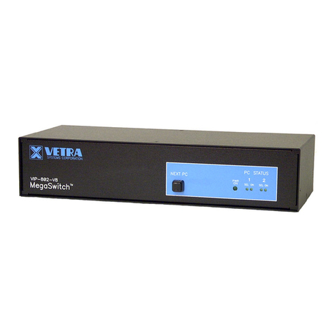
powered up, observe on the Video Switch that the front panel Led marked “PWR ON” comes on.

275 MARCUS BLVD, Suite J, HAUPPAUGE, NY 11788 USA
Tel: 631-434-3185 Fax: 631-434-3516
2. Monitor Selection:
From Front Panel:
“NEXT PC” Button (available on all Standard models):
To select another PC, press the “NEXT PC” pushbutton located on the front panel of the MegaTouch. The MegaTouch will
switch from one PC to the other. If PC #1 is selected the “SEL 1” indicator will be on. If PC #2 is selected then the “SEL 2”
indicator will be on.
2) Direct Entry Buttons (available on -DE models only):
To select another PC, press the MONITOR SELECTION pushbutton for the desired PC number.
Remote Control (available on all models):
The MegaTouch may also be switched via remote control. A Hex 31 code for (PC #1) or Hex 32 for (PC #2) sent via RS-
232 to pin 2 of the DB 9 connector on the rear panel marked “REMOTE CONTROL” will switch the MegaTouch to the
specified PC. The data format is one start bit, eight data bits, least significant bit first, one stop bit and no parity. The baud
rate is 9600. Pin 5 is ground.
SPECIFICATIONS
Mechanical Dimensions
Model #
Height Width Depth Weight
VIP-802-D-TS
3.38” (8.59 cm) 6.06” (15.39 cm) 6.32” (16.05 cm) 1 lb. 7 oz.
VIP-802-D-TS-DE
3.38” (8.59 cm) 6.06” (15.39 cm) 6.32” (16.05 cm) 1 lb. 10 oz.
VIP-802-D2-TS2
3.38” (8.59 cm) 6.06” (15.39 cm) 6.32” (16.05 cm) 1 lb. 7 oz.
VIP-802-D2-TS2-DE
3.38” (8.59 cm) 6.06” (15.39 cm) 6.32” (16.05 cm) 1 lb. 10 oz.
Environmental Operating Temp: 5 to 104 deg. F (-15 - 40 deg. C)
Storage Temp: -4 to 122 deg. F (-20 - 50 deg. C)
Supported Hardware Video Monitors: VGA, SVGA
Maximum Resolution: up to 1600 x 1200 to 75 Hz
FEDERAL COMMUNICATIONS COMMISSION
This equipment has been tested and found to complywith the limits of a Class A digital device, pursuant to Part 15 of the FCC
Rules. These limits are designed to provide reasonable protection against harmful interference when equipment is operated in
a commercial environment. This equipment generates, uses, and can radiate radio frequency energy and, if not installed and
used in accordance with the instruction manual, may cause harmful interference to radio communications. Operation of this
equipment in a residential area is likely to cause harmful interference in which case the user will be required to correct the
interference at their expense.
CE
This equipment has been tested and found to conform to the directives and standards for a Class A Information Technology
Equipment type and for the Commercial Light Industrial equipment class.
MegaTouch is a trademark of Vetra Systems Corporation. Copyright © 1993 - 2011 by Vetra Systems Corporation. All Rights Reserved
This manual suits for next models
3
Table of contents
Other Vetra Systems Switch manuals
Popular Switch manuals by other brands

Dell
Dell PowerConnect 6024 user guide

Hirschmann
Hirschmann GECKO user manual

Brocade Communications Systems
Brocade Communications Systems A7533A - Brocade 4Gb SAN Switch Base Administrator's guide

CYP
CYP EL-C81C Operation manual

Toto Link
Toto Link ZC-SW16 user guide

HP
HP ProCurve Series 2810 Access security guide