Page 3 of 5
275 Marcus Blvd. Ste-J, Hauppauge, NY 11788-2022 USA
Tel 631-434-3185 Fax 631-434-3516
-
Dip Switch Settings.
After setting the Bank Dip switches on the slave units, connect the computers to the slave SwitchCaster units using the
same procedures outlined earlier. The keyboard, mouse and monitor connect to the MASTER only, not to slaves.
To connect to multiple SwitchCaster units, standard Cat5 and VGA HDD15 male-to-female expansion cables are used. To
maintain video quality, it is recommended that high quality, mini-coax, video cables, such as the VETRA model number
VIP-302-CVGA series of cables be used.
Starting at the MASTER unit, connect one end of the Cat5 cable to the RJ-45 connector marked “EXP OUT", the other end
to a slave’s “EXP IN” connector. Connect additional slaves by connecting the “EXP OUT” of one slave to “EXP IN” of
another. To connect video, use a VGA cable to connect the “EXP MON” HDD15 connector on the MASTER unit to the
“MONITOR IN” connector on the next slave. Similarly, connect the next slave by connecting the “EXP MON” HDD15
connector to the “MONITOR IN” connector on the next slave.
OPERATION
1. Power-Up Sequence:
The SwitchCaster is normally powered from connected PC’s. A power on switch, marked POWER, on the front of the
SwitchCaster applies power to the keyboard, mouse and common electronics. It may also be used to reset the
SwitchCaster. The PC's may be powered up in any order, and may be powered down at any time and in any order without
affecting the operation of the SwitchCaster or its attached PC’s. Similarly, the SwitchCaster may be powered down at any
time without affecting the operation of the attached PC’s. However, in a multiple SwitchCaster configuration, if the
MASTER unit has no power, the keyboard, mouse and monitor will not operate
When the SwitchCaster is powered up, check that the front panel LED marked "PWR ON" comes on, and that when PC's
#1 through #8 are powered up their corresponding green "ON" indicators are on.
2. PC Selection:
Selection of a PC to operate (the active PC) can be done either by keyboard hot key sequence, available on all models of
the SwitchCaster or by the “NEXT PC” button on standard models (non DE version) or via Direct Entry switches on the DE
version of the SwitchCaster. In addition to individual selection, the PC’s may be accessed automatically, in sequence, by
invoking the Auto Scan mode. This selection process is slightly different for single unit systems and for expanded systems.
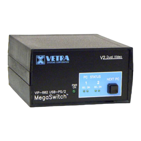
a). The NEXT PC Button (available on Standard models only): Pressing the NEXT PC button cycles you through all
powered PC’s on the SwitchCaster starting from 1 thru 8 and then back to 1 again, or starting from the PC that is already
selected to the next higher numbered PC. If there is no higher numbered PC with power on, the selection cycles to the next
lowest number PC with power. If only one PC is powered, no action occurs. Channels with powered down PC’s or without a
connected PC are skipped. When selection of the PC is complete, the corresponding green “SEL” indicator will be on.
If a SwitchCaster in a multiple unit system has no selected PC and the NEXT PC button is pressed on that SwitchCaster, then
the lowest numbered PC with power becomes the active PC.
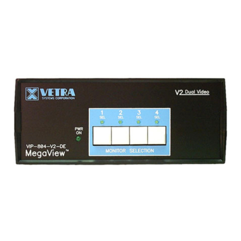
b). Direct Entry (available on DE models only): To select another PC, press the “PC SELECTION” pushbutton for the
appropriate PC desired. When selection of the PC is complete, the corresponding green “SEL” indicator will be on.
c). Keyboard "Hot-Key" Selection (available on all models):
1) Single Unit: To select a PC on a single unit system, first hold down the Scroll Lock Key, then pressing and releasing
the top row keyboard keys 1 – 8. Then release the Scroll Lock key. The number keys must be released before the Scroll
Lock Key. Switching takes place on the release of the Scroll Lock Key, which also rearms the keyboard selection
mechanism. When selection of the PC is complete, the corresponding green “SEL” indicator will be on.
2) Multiple Units (Available on –X Models only): To select a PC on a multiple units system, first hold down the Scroll
Lock, then press and release a top row keyboard key 1 – 8 (this process will select which BANK of switches to access).
Next press and release a top row keyboard key 1 – 8 again (this process will select which specific PC on that BANK to be
active). Then release the Scroll Lock key. Switching takes place on the release of Scroll Lock, which rearms the keyboard
and selection mechanism. When selection of the PC is complete, the corresponding green “SEL” indicator will be on.
