manuals.online logo
Brands
  1. Home
  2. •
  3. Brands
  4. •
  5. Vivotek
  6. •
  7. Switch
  8. •
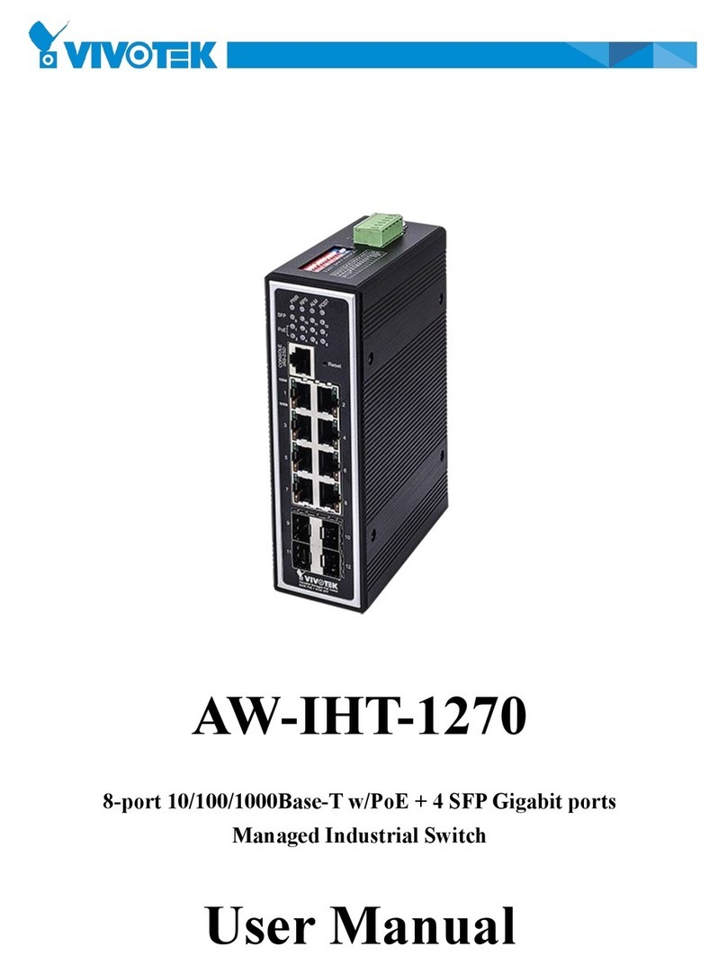
  9. Vivotek AW-IHT-1271 User manual

Vivotek AW-IHT-1271 User manual

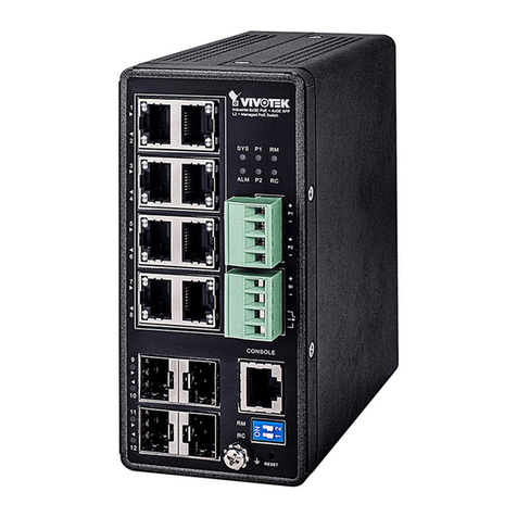
10/100/1000
RJ45 ports
100/100
SFP ports
System LED
Power1 LED
Ring Master LED
Rapid Chain LED
Power2 LED
Alarm LED
DC 54V power input
Digital input
Digital output relay
Console port
DIP switch (Ring Settings)
Reset button
Ground screw
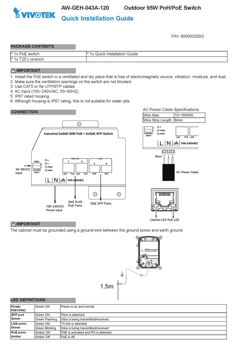
1. Install the converter in a ventilated and dry place that is free of electromagnetic source, vibration, moisture, and dust.
2. Make sure the ventilation openings on the converter are not blocked.
3. Use ber optic cables and transceiver compliant with the following: Multi-mode: 50/125um, 62.5/125um, 850nm;
Single-mode): 9/125um ,1310nm.
4. DC input (48~57VDC). Follow the printed polarity for V+, V-, and Ground.
AW-IHT-1271 Industrial L2+ Managed GbE PoE+ Switch
Quick Installation Guide
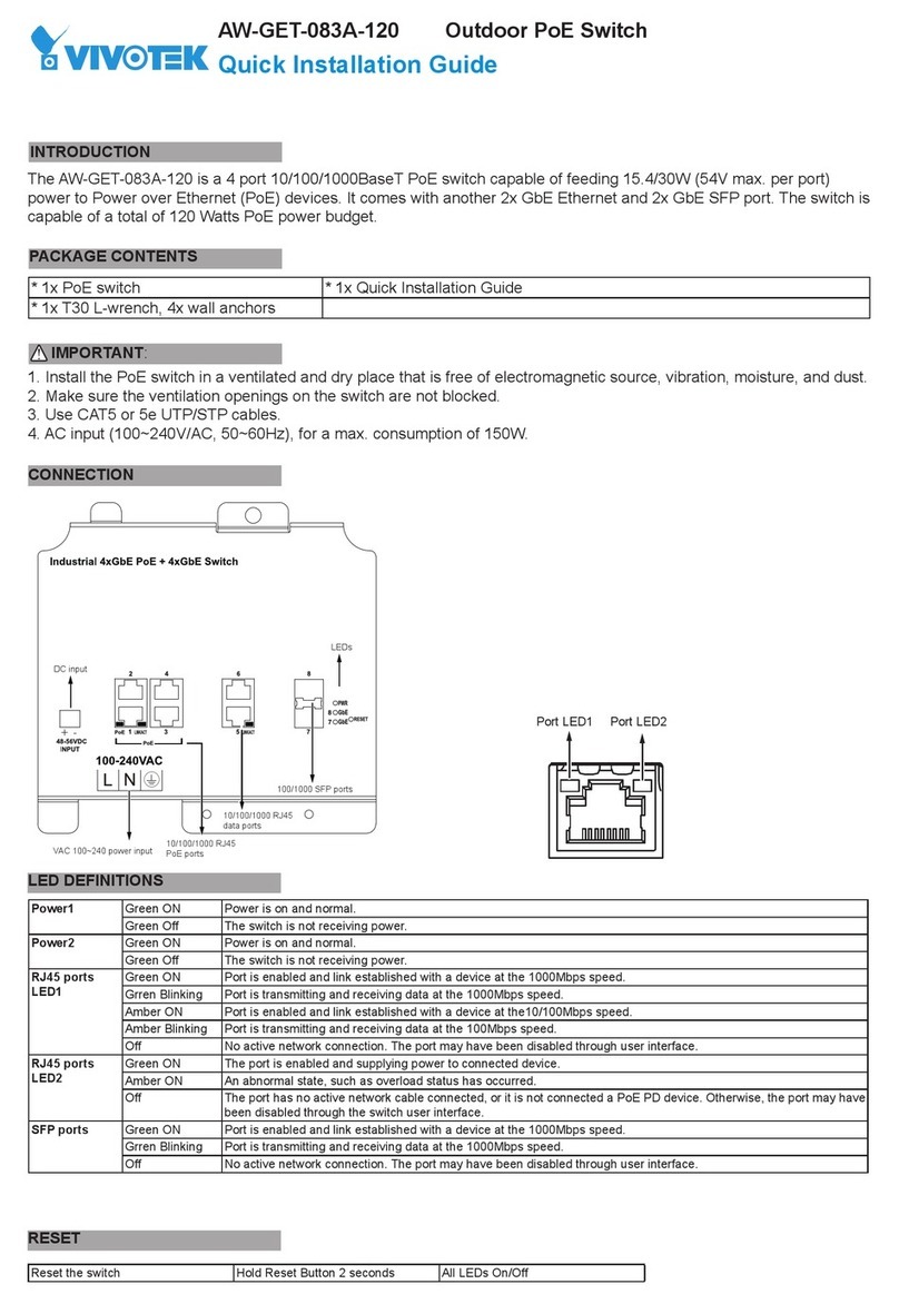
The AW-IHT-1271 managed switch supports 8x GbE PoE+, 4x GbE SFP, and 1x RJ45 console port. It is IEEE 802.3at/
af compliant and delivers the real full-load output of 240W on 8 PoE ports (30W per port). This industrial L2+ managed
switch also features a wide operating temperature range from -40ºC to 75ºC for harsh environment.
IMPORTANT:
INTRODUCTION
CONNECTION
* 1x PoE switch * 1x Quick Installation Guide * 2x 4-pin terminal block
* 1x DB9F-RJ45 console cable * 1x DIN rail bracket
PACKAGE CONTENTS
IP Address DHCP client
Subnet Mask 255.255.255.0
User Name admin
Password admin
DEFAULTS
1. Pull out the 4-pin terminal block.
2. Connect power wires to V+, and V-.
3. Connect SFP transceivers to the ber port.
4. install the 4-pin terminal block.
NOTE: Digital output (relay): 24VDC/1A. Digital input: level 0(Low) -> 0V to 6V,
level 1(High) -> 10V to 24V.
Power LEDs
LED Color State Description
Power1 Green On Powered on correctly.
Off Not receiving power from power1.
Power2 Green On Powered on correctly.
Off Not receiving power from power1.
System LED
LED Color State Description
System Green On Switch is ready.
Off Switch is not ready.
Alarm LED
LED Color State Description
Alarm Red On Abnormal state, such temperature,
voltage, or DC power, has occurred.
Off System is normal.
Ring Master and Rapid Chain LEDs
LED Color State Description
RM
(Ring Master)
Green On Ring Master has been detected.
Amber On Ring Member has been detected.
-Off Disabled.
RC
(Rapid Chain)
Green On Rapid Chain has been detected (Active path).
Amber On Rapid Chain has been detected (Backup path).
Blinking Error, there is no correspondent Rapid Chain switch found.
-Off Disabled.
Baud rate 115200
Stop bits 1
Data bits 8
Parity N
Flow control none
Console Port Defaults
All manuals and user guides at all-guides.com
all-guides.com
VIVOTEK INC.
6F, No.192, Lien-Cheng Rd., Chung-Ho, New Taipei City, 235, Taiwan, R.O.C.
|T:+886-2-82455282|F:+886-2-82455532|E:[email protected]
VIVOTEK USA, INC.
2050 Ringwood Avenue, San Jose, CA 95131
|T: 408-773-8686|F: 408-773-8298|E: [email protected]
VIVOTEK Europe
Randstad 22-133, 1316BW Almere, The Netherlands
T:+31(0)36-5298-434 E:[email protected]
All specications are subject to change without noice.
Copyright © 2018 VIVOTEK INC. All rights reserved.
Port Status LEDs
LED Color State Description
RJ45 Ports
Up
Green On The port is enabled and established a link to connected device, and the speed is 1000Mbps.
Green Blinking The port is transmitting/receiving packets, and the speed is 1000Mbps.
Amber On The port is enabled and established a link to connected device, and the speed is 10/100Mbps.
Amber Blinking The port is transmitting/receiving packets, and the speed is 10/100Mbps.
-Off The port has no active network connection, or it has no established link to connected device.
Otherwise, the port may have been disabled through the switch user interface.
RJ45 Ports
Down
Green On The port is enabled and supplying power to connected device.
Amber On An abnormal state, such as overload status, has been detected in the switch.
-Off The port has no active connection, or it is not connected to a PoE PD device. Otherwise, the port may
have been disabled through the switch user interface.
SFP Ports Green On The port is enabled and established a link to connected device, and the speed is 1000Mbps.
Green Blinking The port is transmitting/receiving packets, and the speed is 1000Mbps.
Amber On The port is enabled and established a link to connected device, and the speed is 100Mbps.
Amber Blinking The port is transmitting/receiving packets, and the speed is 100Mbps.
-Off The port has no active network connection, or it has no established link to connected device.
Otherwise, the port may have been disabled through the switch user interface.
Reset button
Task Method SYS LED Behavior Port Status LED Behavior
Reset Press 2 ~ 7 seconds Blinking Green All LEDs Off.
Restore Defaults Press 2 ~ 7 seconds Blinking Green All LEDS On.
DIN Rail Installation
DIP Switch
O N
1
2
RM
RC
Mode RM RC Rapid Ring status 1st Port 2nd Port LED RM LED RC
HW
Control
Off Off Single Ring member The largest Odd port
number
The largest Even port
number
Amber Off
HW
Control
On Off Single Ring Master The largest Odd port
number
The largest Even port
number
Green Off
HW
Control
Off On Rapid Chain The largest Odd port
number
The largest Even port
number
Off Green (Active path);
Amber (Backup path)
SW
Control
On On Rapid Ring settings
by SW
----
RM: Ring Master
RC: Rapid Chain
All manuals and user guides at all-guides.com

Other manuals for AW-IHT-1271

2

Other Vivotek Switch manuals

Vivotek AW-FGT-100D-120 User manual

Vivotek

Vivotek AW-FGT-100D-120 User manual

Vivotek AW-FGT-100C-120 User manual

Vivotek

Vivotek AW-FGT-100C-120 User manual

Vivotek AW-IHT-1271 User manual

Vivotek

Vivotek AW-IHT-1271 User manual

Vivotek AW-IHT-1271 User manual

Vivotek

Vivotek AW-IHT-1271 User manual

Vivotek AW-GET-094A-130 User manual

Vivotek

Vivotek AW-GET-094A-130 User manual

Vivotek AW-GEH-043A-120 User manual

Vivotek

Vivotek AW-GEH-043A-120 User manual

Vivotek AW-GET-083A-120 User manual

Vivotek

Vivotek AW-GET-083A-120 User manual

Vivotek VivoCam AW-GEV-104B-130 User manual

Vivotek

Vivotek VivoCam AW-GEV-104B-130 User manual

Vivotek AW-FET-100C-120 User manual

Vivotek

Vivotek AW-FET-100C-120 User manual

Vivotek AW-FET-100C User manual

Vivotek

Vivotek AW-FET-100C User manual

Vivotek AW-GEV-104A Series Guide

Vivotek

Vivotek AW-GEV-104A Series Guide

Vivotek AW-FET-053C-120 User manual

Vivotek

Vivotek AW-FET-053C-120 User manual

Vivotek AP-FEX-0105-R User manual

Vivotek

Vivotek AP-FEX-0105-R User manual

Vivotek AW-IHT-1270 User manual

Vivotek

Vivotek AW-IHT-1270 User manual

Vivotek AW-FCT-050A-250 User manual

Vivotek

Vivotek AW-FCT-050A-250 User manual

Vivotek AW-FCT-050A-250 User manual

Vivotek

Vivotek AW-FCT-050A-250 User manual

Vivotek AW-FGT-103C-250 User manual

Vivotek

Vivotek AW-FGT-103C-250 User manual

Popular Switch manuals by other brands

3Com 5-10/100 Specification sheet

3Com

3Com 5-10/100 Specification sheet

Ross Synergy 1 SD manual

Ross

Ross Synergy 1 SD manual

SMC Networks SMC8126L2 Management guide

SMC Networks

SMC Networks SMC8126L2 Management guide

Cudy GS108 Quick installation guide

Cudy

Cudy GS108 Quick installation guide

Logic LG-SS201M user manual

Logic

Logic LG-SS201M user manual

Doepke DPRCD-M1 Usage information

Doepke

Doepke DPRCD-M1 Usage information

EtherWAN EX73900X Series installation guide

EtherWAN

EtherWAN EX73900X Series installation guide

Racepak 500-SW-PNL8 manual

Racepak

Racepak 500-SW-PNL8 manual

Philips US2-PH61153 Specifications

Philips

Philips US2-PH61153 Specifications

NLS CAT5-A2 user guide

NLS

NLS CAT5-A2 user guide

Vivo Link VL120000 user manual

Vivo Link

Vivo Link VL120000 user manual

HP A5120 Series Compliance and Safety Manual

HP

HP A5120 Series Compliance and Safety Manual

Pittway System Sensor EPS40EXP Installation and maintenance instructions

Pittway

Pittway System Sensor EPS40EXP Installation and maintenance instructions

ELBRO SMSB482-V3 user manual

ELBRO

ELBRO SMSB482-V3 user manual

HIK VISION DS-3E0524-E quick start guide

HIK VISION

HIK VISION DS-3E0524-E quick start guide

Fisher DS13 operating manual

Fisher

Fisher DS13 operating manual

GE EntelliGuard G Installation, operation and maintenance guide

GE

GE EntelliGuard G Installation, operation and maintenance guide

Waters Network Systems GSM2109 operating manual

Waters Network Systems

Waters Network Systems GSM2109 operating manual

manuals.online logo
manuals.online logoBrands
  • About & Mission
  • Contact us
  • Privacy Policy
  • Terms and Conditions

Copyright 2025 Manuals.Online. All Rights Reserved.