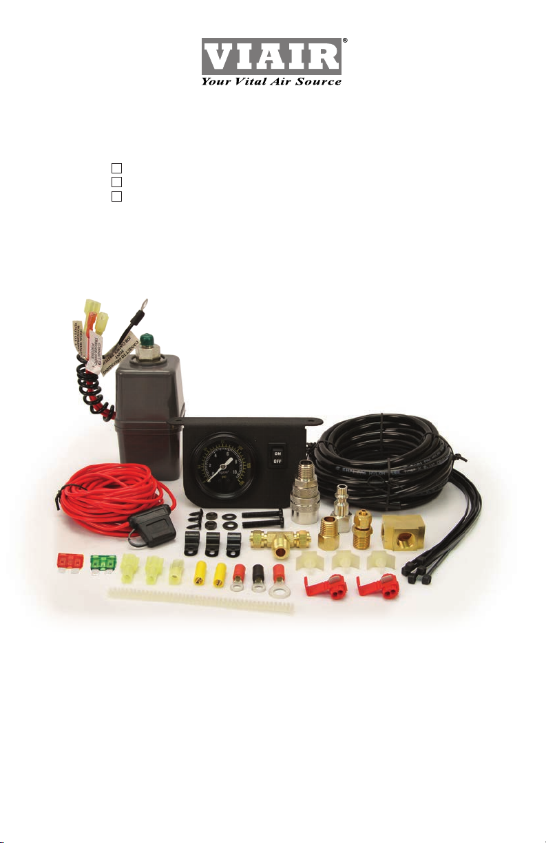
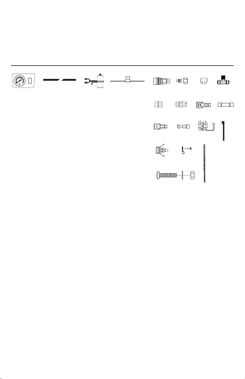
ONBOARD AIR HOOKUP KIT
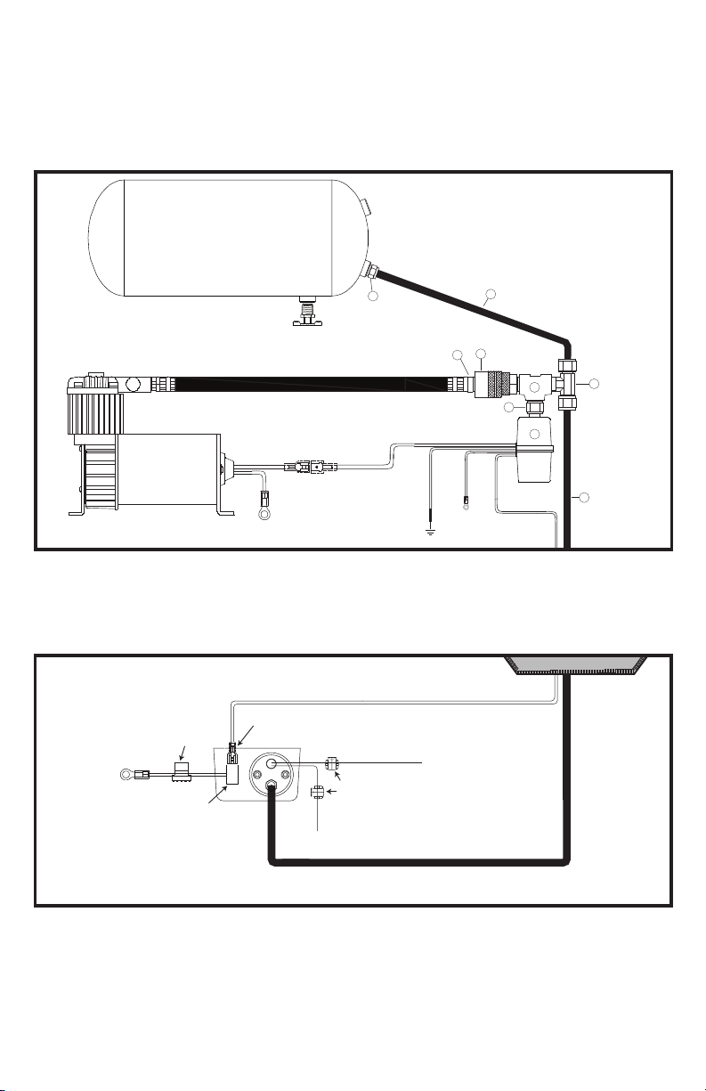
6. Route air line to the male tee, measure and cut to appropriate length. Connect air line to one
leg of the male tee as shown. (See Figs. 3 & 4) To connect air line to tee, remove collar of the
male tee tting, push airline onto the tee tting until the air line completely covers the barb, and
then tighten collar.
7. Attach the pressure switch with built-in relay to the remaining leg of the female tee by using
the included reducer (1/4” M to 1/8” F) (See: Parts List Letter I). Wire the pressure switch
with built in relay according to the instructions located on the pressure switch (See Fig. 3)
8. Place Dash Panel Gauge under dash over the two holes that were drilled. Using the
provided screws, nuts and washers, mount the Dash Panel Gauge to the dash. (See Fig. 4)
9. Route 20 ft. extension lead wire from pressure switch to the dash panel gauge through the same
hole drilled in the rewall for routing the air line. Measure and cut lead wire to appropriate
length. Do not discard the remaining length of the wire, which has the Inline Fuse.
10. Attach one of the two female disconnect terminal to the wire that was routed from
the pressure switch. There are two male spade connectors on the back of the On/Off switch.
Connect the female terminal connector to one of the male spade connector on the On/Off
switch. (See Fig. 4) Next, attach appropriate size ring terminal provided in the kit to the end of
the wire with the Inline Fuse. (The ring terminal will now be about 12” from the Inline Fuse.) This
wire is referred to as the power wire. Temporarily position the ring terminal at the power source
and route power wire to the dash panel gauge, measure and cut to appropriate length. (If
additional wire is necessary, use appropriate gauge wire.) (See Fig. 4)
Attach the remaining female disconnect terminal to end of power wire, and connect to male
spade connector on the ON/OFF switch. (NOTE: Do not connect gauge to power source at
this time).
NOTE: When routing wire, use cable ties included in the kit to secure wire to the vehicle.
11. There are two wires, one red, and one black connected to the light bulb of the gauge. Connect
the red wire to a suitable fused dash panel circuit. Use the quick splice connector included in
the kit for wire connections. See Fig. 2 for how to use the quick splice connector. The black
wire is to be connected to a suitable ground source. Use the ring terminal or the quick splice
connector for ground wire connection. (Note: Consult vehicle manufacturer’s electrical diagram.)
To use the quick splice connector, simply insert wire into one hole of the splice connector, and
slip the connecting wire into the other hole. Once the wires are properly placed, close the top of
the quick splice connector using pliers if necessary. The connector will pierce the wire insulation
to complete wire connection. (Note: If additional wire is required, use 22AWG to 18AWG wire for
quick splice connector.) (See Fig. 2)
12. Connect the remaining length of air line to the remaining leg of the male tee. Route air line from
male tee to air tank, measure and then cut to appropriate length. Use the 1/4” compression
tting provided to connect air line to air tank. (See Fig. 3)
USER MANUAL