ViaSat SurfBeam 2 User manual

Technical Manuals Hard Copy Production Specifications
Comb-Bound Manuals (8-1/2 x 11)
If a hard copy of this manual is required, it should be produced using the following
specifications:
-Input – Electronic Adobe® Acrobat PDF file
-Reproduction method - Digital black and white laser copy machine
-Paper media – 60 pound offset white paper
-Two-sided (double-sided) copy with alternating odd/even page numbers.
-Title page and last page shall be 67 pound vellum Bristol.
-Binding - Bound in center with black comb binding. First and last page (covers) shall be
clear, see-through plastic to allow viewing of title page and last page
-First article printed shall be page-checked for correct format and legibility by ViaSat.
Additional copies shall be randomly checked for correct format and legibility by the printing
service provider.
-Shrink-wrap entire document.
Do not insert this sheet in the manual.
This sheet is provided for printing and assembly instructions only.


SurfBeam®2
Satellite Modem
Outdoor Unit (ODU)
Installation Gu i d e
ViaSat Document Number
1104460
(Rev. 001)
SM2 Software Release 1.0 and higher
ViaSat, Inc.
6155 El Camino Real
Carlsbad, CA 92009-1699
Tel: (760) 476-2200
Fax: (760) 929-3941
www.viasat.com


REGULATORY COMPLIANCE and NOTICES
This device complies with part 15 of the FCC Rules. Operation is subjected to the following two conditions:
FCC Notice
1. This device may not cause harmful interference, and
2. This device must accept any interference received, including interference that may cause undesired operation.
NOTE: This equipment has been tested and found to comply with the limits for a Class B digital device, pursuant to Part 15 of
the FCC Rules. These limits are designed to provide reasonable protection against harmful interference in a residential
installation. This equipment generates, uses and can radiate radio frequency energy and, if not installed and used in accordance
with the instructions, may cause harmful interference to radio communications. However, there is no guarantee that interference
will not occur in a particular installation. If this equipment does cause harmful interference to radio or television reception,
which can be determined by turning the equipment off and on, the user is encouraged to try to correct the interference by one or
more of the following measures:
-- Reorient or relocate the receiving antenna.
-- Increase the separation between the equipment and receiver.
-- Connect the equipment into an outlet on a circuit different from that to which the receiver is connected.
-- Consult the dealer or an experienced radio/TV technician for help.
Any changes or modifications not expressly approved in writing by the manufacturer could void the user’s authority to operate
the equipment.
CAUTION: Shielded I/O cables must be used and all covers must be in place when operating this equipment.
Canadian Department of Communications compliance statement:
ROHS Compliant Notice (Restriction of Hazardous Substances)
This digital apparatus does not exceed the Class B
limits for radio noise emissions from digital apparatus as set out in the Radio Interference Regulation of the Canadian
Department of Communications.
This product and its components are in compliance with Directive 2002/95/EC of the European Parliament.
REACH Compliant Notice
This product and its components are in compliance with EU Directive 1907/2006/EC.
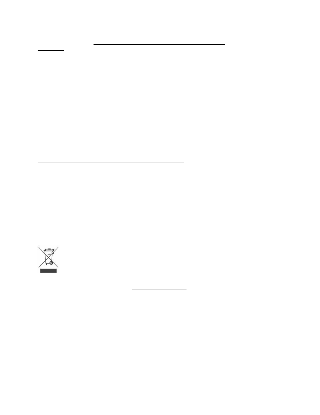
WEEE Notice (Waste Electrical and Electronic Equipment)
ViaSat has marked this product with the WEEE symbol as a convenience to its customers for environmental responsibility per
European Union Directive 2002/96/EC. This product shall be collected and disposed of in accordance with national and local
laws. Waste electrical and electronic products must not be disposed of with household waste. For information on proper disposal,
contact your equipment distributor or service provider.
If additional information is required you may send correspondence to: Compliance-ProductEnvironmental@viasat.com
©Copyright 2011 ViaSat, Inc.
COPYRIGHT NOTICE
All rights reserved under the copyright laws of the U.S.
TRADEMARK NOTICE
SurfBeam®, the SurfBeam®logo, ViaSat and the ViaSat logo are trademarks or registered trademarks of ViaSat, Inc. in the U.S.
and/or other countries. Other product names included in this document are trademarks of their respective owners.
DOCUMENTATION NOTICE
The information, specifications, and features contained in this document are subject to change without notice and should not be construed as a
commitment by ViaSat, Inc.
ViaSat, Inc. assumes no responsibility for any errors that may appear in this document nor does it make an expressed or implied
warranty of any kind with regard to this material, including, but not limited to, the implied warranties of merchantability and fitness for
a particular purpose. ViaSat, Inc. shall not be liable for incidental or consequential damages in conjunction with, or arising out of the
furnishing, performance, or use of this document or the product it describes.


SurfBeam®2 Satellite Modem Outdoor Unit (ODU)
Installation Guide
Rev. 001 1104460 i
Revision History
Revision Rationale Release Date Affected
001 Initial Release 23 Feb., 2011 All pages

SurfBeam®2 Satellite Modem Outdoor Unit (ODU)
Installation Guide
ii 1104460 Rev. 001
Warranty Information
ViaSat, Inc. does not provide a warranty to the end user for this product. Any such warranty
from ViaSat, including the implied warranty of merchantability or fitness for a particular
purpose, is hereby disclaimed.
Your service provider may provide a warranty for this product. For warranty information and
repairs, please contact your service provider.
Warnings, Cautions, and Notes
Safety precautions or important information found in this document will normally be presented
just before the point where the hazard is likely to be encountered. Symbols used to identify the
information are defined as follows:
Warning This symbol indicates a procedure or practice that, if not correctly followed, could
result in injury, death, or long term health hazard.
Caution This symbol indicates a procedure or practices that, if not correctly followed, could
result in equipment damage, or destruction.
This symbol indicates a procedure or practices that, if not correctly followed, could
result in serious equipment damage, or destruction, or could be life threatening.
This symbol indicates that a radiation source may be present and care should be
taken to follow all safety advisories.
This symbol indicates that a hot surface may be present and care should be taken to
follow all safety advisories.
Note
This symbol indicates information that is important to observe.

SurfBeam®2 Satellite Modem Outdoor Unit (ODU)
Installation Guide
Rev. 001 1104460 iii
Important Safety Precautions and Notices
Warnings.
Assembling dish antennas on windy days can be dangerous. The antenna surface, even in slight winds, creates
strong forces. For example, a 1.0m antenna facing a wind of 32km/h (20 mph) can undergo forces of 269 N (60 lbs). Be
prepared to handle those forces safely at unexpected moments. Do not attempt to assemble, move, or mount a dish
on high wind days or serious, even fatal, accidents may occur. The Vendor is not responsible or liable for damage or
injury resulting from antenna installations.
Antennas improperly installed or installed to an inadequate structure are very susceptive to wind damage. This
damage can be very serious or even life threatening. The owner and installer assume full responsibility that the
installation is structurally sound to support all loads (weight, wind and ice) and properly sealed against leaks. The
Vendor is not responsible for any damage caused by an antenna due to installations that do not follow this
instruction.
WATCH OUT FOR WIRES! Installation of this product near power lines is dangerous. For your own safety, follow
these important safety rules.
1. Perform as many functions as possible on the ground.
2. Watch out for overhead power lines. Check the distance to the power lines before starting installation. We
recommend you stay a minimum of 6 meters (20 feet) from all power lines.
3. Do not install the antenna or mount assembly on a windy day.
4. If you start to drop the antenna or mount assembly, get away from it and let it fall.
5. If any part of the antenna or mount assembly comes into contact with a power line, call your local power
company. DO NOT TRY TO REMOVE IT YOURSELF! They will remove it safely.
6. Properly ground the antenna assembly according to all federal and local electrically codes.
Cautions.
This instruction will assist you in the correct installation of the product. Read it prior to starting any installation work.
Due to the nature of the method of manufacture, there may be sharp edges on metal components. Be cautious when
un-packing and handling antenna parts.
When this antenna is connected to a transceiver (TRIA), and powered on through interconnection to a satellite
modem, a radiation source can be present. The transmitter will turn on only once a proper receive signal is obtained.
Caution must be used upon completion of alignment to the satellite, and once the installation of the system has been
completed. When the transmitter is operational, keep away a distance of 60 cm (2 feet). For additional information,
contact your service provider.
When this antenna is powered on, the transceiver (TRIA) can get hot can be present burn danger to
skin. Caution must be used upon turning power on the system. Do not touch the transceiver (TRIA).
Notes
This product was qualified under test conditions that included the use of the supplied cable between system
components. To be in compliance with regulations, the user must use this cable and install it properly.
Different types of cord sets may be used for connections to the main supply circuit. Use only a main line cord that
complies with all applicable product safety requirements of the country of use.
Installation of this product must be in accordance with national wiring codes.
ViaSat, Inc. declares that this Satellite Modem is cULus Listed and is in compliance with Canadian and U.S.
safety standards and complies with the RoHS directive for hazardous materials reduction.
ViaSat, Inc. declares that this Satellite Modem is in compliance with the essential requirements and other relevant
provisions of Directive 1999/5/EC.

SurfBeam®2 Satellite Modem Outdoor Unit (ODU)
Installation Guide
iv 1104460 Rev. 001
This manual contains installation and configuration information about the SurfBeam 2 Satellite
Modem Outdoor Unit (ODU).
About This Manual
For information on installation and configuration of the SurfBeam 2 Satellite Modem Indoor
Unit (IDU) refer to the SurfBeam 2 Satellite Modem Indoor Unit (IDU) Installation and Setup
Guide, 1104467-001.
Additional publications and information including user guides, white papers, application notes,
release notes, SNMP MIB downloads, software updates, training schedules, and other technical
information may be found on the ViaSat Customer Portal web site. The Customer Portal may be
accessed through the ViaSat web site located at this URL:
Obtaining Additional Publications and Information
http://viasat.com/
Customers may apply for password access to the Customer Portal by clicking on the Customer
Login link and following the link to create a new account.

SurfBeam®2 Satellite Modem Outdoor Unit (ODU)
Installation Guide
Rev. 001 1104460 v
Table of Contents
1ANTENNA ASSEMBLY – GENERAL INFORMATION..........................................................................1-1
1.1 Tools and Hardware Required......................................................................................................................1-1
2ASSEMBLING A MID POLE ODU .............................................................................................................2-1
2.1 Unpacking the Antenna................................................................................................................................2-1
2.2 Antenna Assembly .......................................................................................................................................2-1
3ASSEMBLING A TOP POLE ODU .............................................................................................................3-1
3.1 Unpacking the Antenna................................................................................................................................3-1
3.2 Antenna Assembly .......................................................................................................................................3-1
4MOUNTING THE ANTENNA ON A TRI MAST ......................................................................................4-1
5RECOMMENDED CABLING AND GROUNDING ..................................................................................5-1
6SUMMARY OF ODU MOUNTING OPTIONS ..........................................................................................6-1
6.1 Mid-Pole Mounting Configurations .............................................................................................................6-1
6.2 Universal Mounting Configurations.............................................................................................................6-3
6.3 Top Pole Mounting Configurations..............................................................................................................6-4
List of Figures
Figure 1-1. Never Rest Dish on its Edge ...................................................................................................................1-2
Figure 1-2. Tools and Additional Materials................................................................................................................1-4
Figure 1-3. Fasteners (1 of 3) ....................................................................................................................................1-4
Figure 1-4. Mid Pole ODU Az/El Box Components (2 of 3) ....................................................................................1-5
Figure 1-5. TRIA (3 of 3)..........................................................................................................................................1-5
Figure 2-1. Initial Adjustments for Antenna Assembly.............................................................................................2-1
Figure 2-2. Elevation Bracket Assembly....................................................................................................................2-3
Figure 2-3. Setting the Skew ......................................................................................................................................2-4
Figure 2-4. Assembly of Boom Arms........................................................................................................................2-5
Figure 2-5. Assembly of TRIA Support Bracket.......................................................................................................2-6
Figure 2-6. The TRIA Assembly...............................................................................................................................2-7
Figure 2-7. Mounting of TRIA Assembly. ................................................................................................................2-8
Figure 2-8. Attaching Ground Wire to TRIA. ............................................................................................................2-9
Figure 2-9. Attaching the Ground Wire to Boom Arm and Azimuth/Elevation Plate..............................................2-10
Figure 2-10. Clamping ODU Assembly to Pole......................................................................................................2-11
Figure 2-11. Tightening the Clamps.........................................................................................................................2-12
Figure 2-12 Mounting the Boom Arms. ...................................................................................................................2-13
Figure 2-13. Initial Mounting of Receiver Dish (1)..................................................................................................2-14
Figure 2-14. Mounting of Receiver Dish (2) ...........................................................................................................2-14
Figure 3-1. Hardware Included with Top Pole ODU..................................................................................................3-1
Figure 3-2. Elevation Bracket Assembly....................................................................................................................3-3
Figure 3-3. Setting the Skew. .....................................................................................................................................3-4
Figure 3-4. Assembly of Boom Arms.........................................................................................................................3-5
Figure 3-5. The TRIA Assembly................................................................................................................................3-6
Figure 3-6. Mounting of TRIA to Support Bracket....................................................................................................3-7
Figure 3-7. Attaching Ground Wire to TRIA.............................................................................................................3-8
Figure 3-8. Mounting Elevation Bracket to Pole........................................................................................................3-9
Figure 3-9. Mounting the Boom Arms. ....................................................................................................................3-10
Figure 3-10. Attaching the Ground Wire to Boom Arm and Elevation Bracket.......................................................3-11
Figure 3-11. Mounting the Receiver Dish. ...............................................................................................................3-12
Figure 4-1. Tri Mast Mounting Bracket.....................................................................................................................4-2
Figure 4-2. Assembling the Mount Tube to the Mount Bracket.................................................................................4-2
Figure 4-3. Attaching the Stays to the Mount Tube....................................................................................................4-3

SurfBeam®2 Satellite Modem Outdoor Unit (ODU)
Installation Guide
vi 1104460 Rev. 001
Figure 4-4. Wall and Roof Mounting Options............................................................................................................4-4
Figure 4-5. Sliding Mounting Bracket Canister onto Pole or Mast. ...........................................................................4-5
Figure 5-1. TRIA Connections ..................................................................................................................................5-1
Figure 6-1. ODU Installed on Mid-Pole Mount..........................................................................................................6-1
Figure 6-2. ODU Mid Pole Mount with Optional Wall or Roof Mounting Hardware. ..............................................6-2
Figure 6-3. ODU Universal Mount with Optional Wall and Roof Mounting Hardware. ...........................................6-3
Figure 6-4. ODU Top Mount on Pole.........................................................................................................................6-4
Figure 6-5. Optional Pole Mount Adaptor..................................................................................................................6-5
List of Tables
Table 1-1. Reflector Assembly Box ..........................................................................................................................1-3
Table 1-2. Inner Az/EI Box.......................................................................................................................................1-3
Table 1-3. Main Outer Box........................................................................................................................................1-3

SurfBeam®2 Satellite Modem Outdoor Unit (ODU)
Installation Guide
Rev. 001 1104460 1-1
1ANTENNA ASSEMBLY – GENERAL INFORMATION
1.1 Tools and Hardware Required
Antenna Installation will require the use of the following tools.
•Ratchet driver
•No 2 Pozi-drive / Philips screw driver
•13 mm (or ½”) socket
•13 mm (or 1/2”) open-ended spanner wrench
•8 mm (or 5/16th) socket
•8 mm (or 5/16”) open-ended spanner wrench
Additional Materials:
•Weather grade silicon sealant
•Approved RG6 Cable
•UV rated cable ties
Package Contents:
To avoid potential damage, the Eutelsat Tooway Ka antenna should remain in its protective
packaging until it is required for installation.
Note Figure 1-1: Never rest the dish on its edge as shown in .

SurfBeam®2 Satellite Modem Outdoor Unit (ODU)
Installation Guide
1-2 1104460 Rev. 001
Figure 1-1. Never Rest Dish on its Edge
Suggested Installation Environment
Note: Do not install antenna in a location where the line of sight to the satellite is blocked by
trees or tall buildings. Attempting fine pointing during periods of dense cloud cover with
precipitation may not be successful.

SurfBeam®2 Satellite Modem Outdoor Unit (ODU)
Installation Guide
Rev. 001 1104460 1-3
Table 1-1 through Table 1-3 list components required for antenna assembly. Figure 1-2 through
Figure 1-5 depict the hardware lists required for antenna assembly.
Table 1-1. Reflector Assembly Box
Number Description Qty
1 Reflector 1
2 Antenna Back Bracket 1
3 Skew Plate 1
4 Boom Arm 2
5 TRIA Mounting Bracket 1
6 M8 Spring Washer 8
7 M8 Washer 12
8 M5 Spring Washer 4
9 M8 x 20 mm Carriage Bolt 9
10 M8 Nut 8
11 M8 Serrated Nut 9
12 M8 x 20 mm Hex Head Bolt 4
13 M8 x 45 mm Carriage Bolt 4
14 M5 Pozi Pan Screw 4
Table 1-2. Inner Az/EI Box (mid pole)
Number Description Qty
15 Elevation Bracket 1
16 U-shaped Pole Clamp Bolt 2
17 Pole Clamp Bar 2
18 Flange Nuts 4
19 M5 x 25mm Hex Head Bolt 1
20 M5 Tooth Lock Washer 1
21 M5 Hex Nut 1
22 Grounding Wire 1
Table 1-3. Main Outer Box
Number Description Qty
23 TRIA Assembly 1

SurfBeam®2 Satellite Modem Outdoor Unit (ODU)
Installation Guide
1-4 1104460 Rev. 001
Figure 1-2. Tools and Additional Materials
Figure 1-3. Fasteners (1 of 3) Top Pole

SurfBeam®2 Satellite Modem Outdoor Unit (ODU)
Installation Guide
Rev. 001 1104460 1-5
Figure 1-4. Mid Pole ODU Az/El Box Components (2 of 3)
Figure 1-5. TRIA (3 of 3)
There are two versions of ODU elevation bracket, one mounts in the middle of a support pole,
the other mounts on the top of a pole or a tri mast assembly. The assembly of these two ODU
versions is covered separately on the following pages.

SurfBeam®2 Satellite Modem Outdoor Unit (ODU)
Installation Guide
1-6 1104460 Rev. 001

SurfBeam®2 Satellite Modem Outdoor Unit (ODU)
Installation Guide
Rev. 001 1104460 2-1
2ASSEMBLING A MID POLE ODU
The mid pole ODU has clamps that allow it to be mounted on a pole.
2.1 Unpacking the Antenna
Remove the antenna dish and set it aside while still in its protective shipping material. Do not
remove the dish until ready to install it.
Caution Do not rest the dish on its side or lay it flat if removed from shipping material!
2.2 Antenna Assembly
Complete the antenna assembly on the ground, before mounting it on the Mounting pole. This
assembly has seven steps.
Step 1: Adjustments for Antenna Assembly
At this point the elevation setting should be pre-set as per the Work Order# to the approximate
value. In order to do this, ensure the elevation lock down nuts are loosened, and then manually
adjust the elevation setting to the relevant position.
When the coarse elevation adjustment is complete, tighten the elevation lock down nuts. This
will secure the setting while the antenna is assembled.
Figure 2-1. Initial Adjustments for Antenna Assembly

SurfBeam®2 Satellite Modem Outdoor Unit (ODU)
Installation Guide
2-2 1104460 Rev. 001
Step 2: Fasten Antenna Back Bracket to Elevation Plate
Construct the Elevation, Azimuth, and Skew Adjustment Assembly by fastening the Skew Plate
to the front of the Elevation Bracket, through the Antenna Back Bracket.
Ensure that you align the A arrows. Pass four M8 x 20mm Carriage Bolts through the skew
plate, then the Antenna Back Bracket, and, finally, through the front of the Elevation Bracket.
Secure the Skew Plate using a M8 Washer, M8 Spring Washer, and a M8 Hex Nut on each
Carriage Bolt, as in (Figure 2-2).
Set the skew to 90 degrees, as shown in Figure 2-3. Tighten hardware with a 13mm (or 1/2")
wrench.
Other manuals for SurfBeam 2
3
Table of contents
Other ViaSat Modem manuals