Viasat Business Hotspots Installation Guide
Page | 7
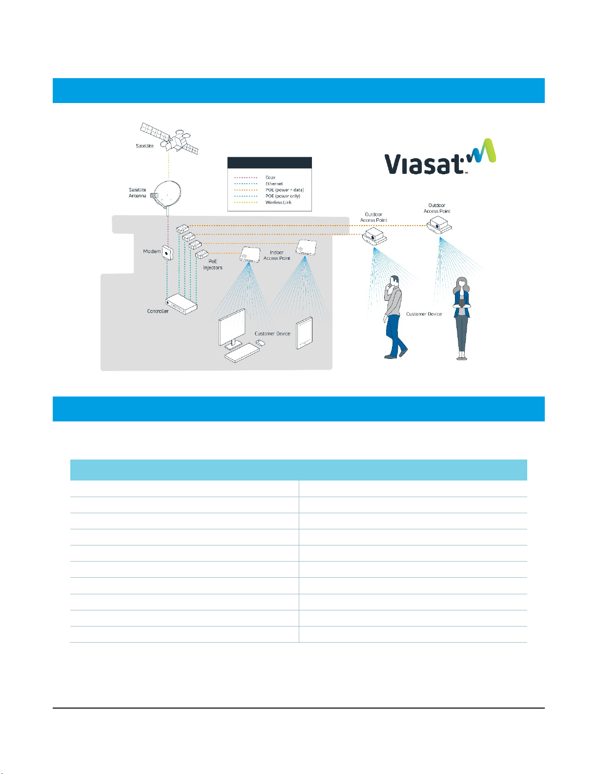
Installation instructions
This installation guide provides comprehensive instructions for equipment installation and documentation
when adding the Business Hotspots network to the Viasat Satellite Internet solution.
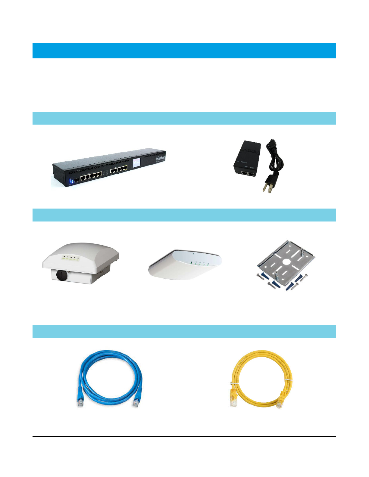
Step 1 | Select equipment location
Outdoor AP & satellite antenna Indoor equipment
Select a secure location with clear line of site where the
most Wi-Fi users will be reached, preferably overlooking
a gathering area.
Install within 300 cable-feet of the controller at the
minimum height specified in Step 3 below.
Select a secure, climate-controlled location near a
power source and the modem for installing the
controller and PoE injector/s.
Install the indoor AP at ceiling level as close as possible
to the center of the intended coverage area where the
most Wi-Fi users will connect.
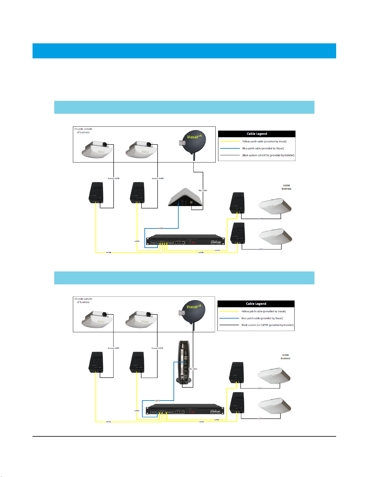
Step 2 | Install CAT5e cable
For each outdoor AP, cut to length (1) outdoor-rated CAT5e Ethernet cable no more than 300 cable-feet from
the location where the controller will be installed to the location where the AP will be mounted. Terminate
the ends and test each cable with a CAT5e cable tester. Install the cable, ensuring any holes that penetrate
the building are sealed.
For each indoor AP, cut to length (1) standard CAT5e Ethernet cable no more than 300 cable-feet from the
location where the controller will be installed to the location where the AP will be mounted. Terminate the
ends and test each cable with a CAT5e cable tester.
NOTE: Wait to tie down the cables until after all equipment is installed, configured and tested.
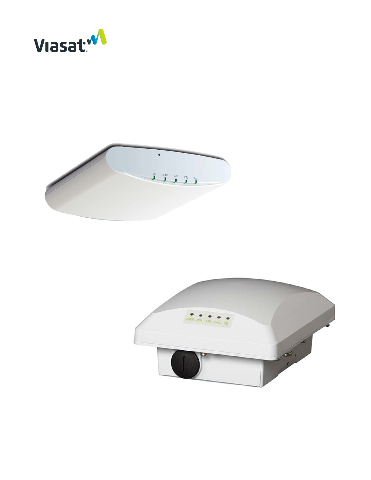
Step 3 | Mount the outdoor AP/s
Mount the outdoor AP/s in a secure location within 300 cable-feet of the controller. The outdoor AP must be
mounted with clear line of site to the Wi-Fi users in either of the following locations:
» A wall or outdoor patio-type ceiling at a minimum height of 10ft. (if ceiling is lower, mount at ceiling
height)
» A roof using a pole mount at a minimum of 2ft. and maximum of 10ft. above the roof, as long as there
is clear line of site to the users (follow the Viasat-approved Low-profile Pole Mount or Stub-mount
instructions)
Refer to the Ruckus Outdoor AP installation instructions in this guide for additional information.
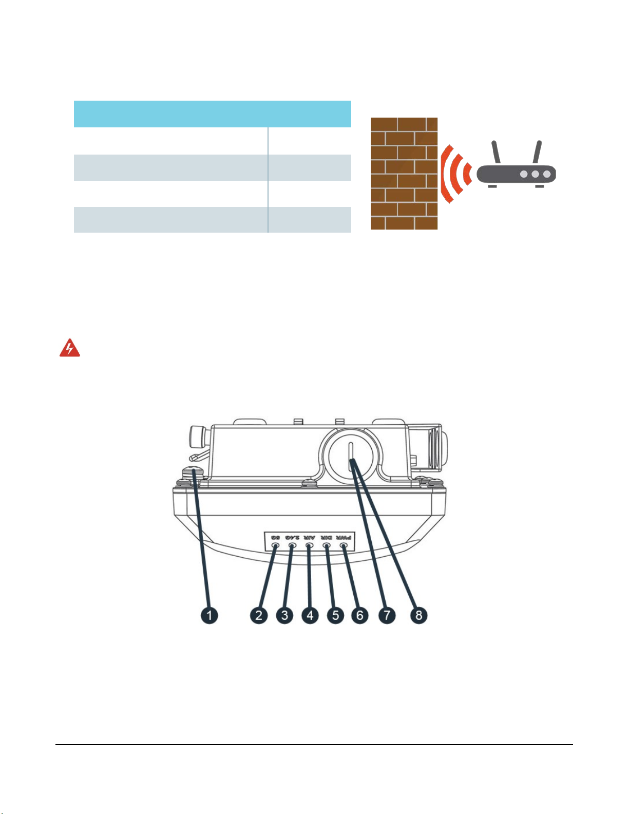
Avoid barriers and signal interference
The access point must be in a location that has clear line of site to the users, avoiding obstructions such as
buildings, trees, shrubs or any large structure that prevents clear line of site.