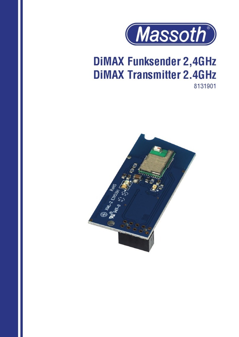
Massoth 8131901 User manual

DiMAX Funksender 2.4GHz
DiMAX Transmitter 2.4GHz
8131901
Firmware 2.0

2
1. Einleitende Information
Sehr geehrte Kunden, mit dem Di-
MAX Funksender 2,4GHz haben sie
ein hochwertiges Produkt „Made
in Germany“ erworben. Dieser
erweitert den DiMAX Navigator
zum Funkhandregler.
1.1 Lieferumfang
•Funksender
•Bedienungsanleitung
1.2 Warnhinweise
•Diese Bedienungsanleitung gilt
ab Firmware Version 2.0 und
höher. Stellen Sie sicher, dass alle
eingesetzen Funkkomponenten
(Funksender und Funkempfänger)
mindestens diesen Versionstand
haben. Der Navigator sollte minde-
stens Fimware Version 2.20 haben.
•Dieses Produkt ist kein Spielzeug.
•Die Reichweite ist von den ört-
lichen Gegebenheiten abhängig.
•Fremde Sender auf gleicher Fre-
quenz sowie Hindernisse zwischen
Sender und Empfänger (z.B.
Wände) können den Funkverkehr
einschränken.
1. Introduction
Dear Customer, with this DiMAX
R/C Transmitter 2.4 GHz you have
purchased a high quality product
„Made in Germany“. It upgrades
the DiMAX Navigator to a R/C
controller.
1.1 Scope of supply
•Transmitter
•Users Manual
1.2 Warning Notes
•These operating instructions are
validforrmwareversion2.0
and higher. Make sure that all
radio components used (radio
transmitters and radio receivers)
have at least this version status.
The DiMAX Navigator should have
rmwareversion2.2.
•This product is not a toy!
•The range depends on the local
conditions.
•Foreign transmitters using the
same frequency or other obstacles
between transmitter and receiver
(e.g. walls) may reduce or limit
radiotrafc.

3
2. Einbau
Lösen Sie die fünf Schrauben wie in
Abbildung #1 auf der folgenden Sei-
te gezeigt. Nachdem sie die Rück-
seite des Gehäuses abgenommen
haben, sehen sie die Hauptplatine
(Abbildung 2), die Buchse für das
Buskabel sowie das Display. Rechts
unterhalbdesDisplaysbendet
sich der Sockel mit 10 Stiften zur
Aufnahme des Funkmoduls. Stecken
sie hier wie aus der Zeichnung
ersichtlich den Funksender auf.
Beachten sie dabei unbedingt, dass
der Sockel des Senders richtig auf
den Stiften unterhalb des Displays
sitzt und diese korrekt im Sockel
des Funksenders eingesteckt sind.
Ist der Sender nicht ordnungs-
gemäß eingesteckt führt dies
zu irreparablen Schäden an der
Elektronik. Setzen Sie anschließend
die Rückseite des Gehäuses wieder
auf und verschrauben es.
2. Installation
Loosenthevescrewsasshown
in Figure #1 on the following
page. After removing the back
of the housing, you will see the
main board (Figure #2), the
socket for the bus cable and the
display. Right below the display
is the socket with 10 pins for the
transmitter. Insert the transmitter
here as shown in the drawing.
Make sure that the base of the
transmitter is correctly positioned
on the pins below the display and
that these are correctly inserted
in the base of the transmitter. If
the transmitter is not inserted cor-
rectly, this will lead to irreparable
damage to the electronics. Then
install the back of the housing and
screw it in place.

4
Abbildung 1: Öffnen der Rückwand
Illustration #1: Opening the backplane

5
Abbildung 2: Einbau des Funksenders
Illustration #2: Assembling the RC sender

6
3. Radio connection
After installing the transmitter, it
must be activated in the settings
of the hand controller. For details,
please refer to the operating
instructions of the Navigator. We
also recommend reading the ope-
rating instructions of the receiver.
To simplify commissioning, the
receiver automatically allows the
initial registration of a navigator.
However, this option is only availa-
ble as long as the receiver is in the
delivery state. Once the receiver
has been connected to a navigator,
automatic registration of further
navigators is no longer possible.
3.1 Automatic initial registration
As soon as the radio receiver
startsandthestatusLEDashes
quickly symmetrically, the receiver
is ready for the automatic initial
registration of the Navigator. The
Navigator will automatically con-
nect to the receiver when switched
on. After resetting the receiver
to factory settings (see page 11,
chapter 4), the automatic initial re-
3. Funkverbindung
Nach dem Einbau des Funksenders
muss dieser in den Einstel-
lungen des Handreglers aktiviert
werden. Details entnehmen Sie
bitte der Bedienungsanleitung
des Navigators. Wir empfehlen
auch die Bedienungsanleitung des
Funkempfängers zu lesen.
Zur Vereinfachung der Inbetrieb-
nahme erlaubt der Empfänger die
Erstanmeldung eines Navigators
automatisch. Diese Möglichkeit
besteht jedoch nur solange, wie
sich der Empfänger im Ausliefe-
rungszustandbendet.Sobald
der Empfänger einmal mit einem
Navigator verbunden wurde, ist
eine automatische Anmeldung
weiterer Navigatoren nicht mehr
möglich.
3.1 Automatische Erstanmeldung
Sobald der Funkempfänger startet
und die Status-LED schnell sym-
metrisch blinkt, ist der Empfänger
für die automatische Erstanmel-
dung des Navigators bereit. Der
Navigator verbindet sich beim
Einschalten automatisch mit dem
Empfänger. Nach Rücksetzen des
Empfängers auf Werkeinstellung
(siehe Seite 11, Kapitel 4) ist die

7
gistration is active again. In order
for the navigator to automatically
log on to the receiver, there must
not have been a radio connection
yet. For this purpose, please read
the operating instructions of the
navigator.
3.2 Regular registration
If a handheld controller has alrea-
dy been registered on the receiver
once, automatic initial registration
is no longer possible.
•For further login (or if the automa-
tic initial login was not successful),
put the receiver into connection
mode. To do this, press the button
onthereceiverforapprox.ve
seconds until the status LED
ashesquicklyandsymmetrically.
WhiletheLEDisashing,youcan
register another navigator. Start
the connection mode in the hand-
set control menu. The receiver
automatically ends the connection
mode after approx. 60 seconds if
no hand controller registers.
•Radio subscribers who are already
logged in can reconnect without
logging in again. If this does not
work, either the maximum number
of possible radio participants has
been reached or a factory reset
has been performed. The oldest
automatische Erstanmeldung wie-
der aktiv. Damit der Navigator sich
automatisch am Empfänger anmel-
det, darf noch keine Funkverbin-
dung bestanden haben. Lesen Sie
dazu bitte die Bedienungsanleitung
des Navigators.
3.2 Reguläre Anmeldung
Wurde bereits einmal ein Handreg-
ler am Empfänger angemeldet, ist
die automatische Erstanmeldung
nicht mehr möglich.
•Für weitere Anmeldung (oder
wenn die automatische Erstan-
meldung nicht erfolgreich war)
bringen Sie den Empfänger in den
Verbindungsmodus. Dazu drücken
sie den Taster am Empfänger ca.
fünf Sekunden, bis die Status-
LED schnell symmetrisch blinkt.
Während des Blinkens können
sie einen weiteren Navigator
anmelden. Starten Sie im Handreg-
lermenü den Verbindungmodus.
Der Empfänger beendet den
Verbindungsmodus nach ca. 60
Sekunden automatisch, falls sich
kein Handregler anmeldet.
•Bereits angemeldete Funkteilneh-
mer können sich ohne erneute
Anmeldung wieder verbinden.
Sofern dies nicht funktioniert, ist
entweder die maximale Anzahl

8
navigator is always deleted from
the system‘s connection list. In
this case, the handheld controller
must be logged in again.
3.3 Radio connection type
•STD: Usually, the navigator con-
nects with a standard connection
(STD), which means that all hand
controllers have normal status. If a
fthhandcontrollerisregistered,
the oldest, non-active hand
controller is automatically deleted
from the receiver.
•PRI: Up to two navigators can be
connected with priority (PRI). This
means that they are not automati-
cally removed from the connection
list. This is particularly useful if
you want to ensure that a selected
hand controller always has access
to the system (for example, on
club installations). Thus, in the
case of regularly changing users,
the hand controller with priority al-
ways has the right to intervene. To
activate this function, the PRI (Pri-
ority) option must be selected in
the radio menu of your navigator.
This works only when the radio
der möglichen vier Funkteilehmer
erreicht, oder ein Werksreset
wurde vorgenommen. Aus der
Verbindungsliste des Systems
wird immer der älteste Navigator
gelöscht. In diesem Fall muss der
Handregler wieder neu angemeldet
werden.
3.3 Art der Funkverbindungen
•STD: Üblicherweise verbindet sich
der Navigator mit einer Standard-
verbindung (STD), das bedeutet,
alle Handregler haben normalen
Status. Wird ein fünfter Handregler
angemeldet, wird automatisch der
älteste, nicht aktive Handregler aus
dem Empfänger gelöscht.
•PRI: Bis zu zwei Navigatoren kön-
nen mit Priorität (PRI) verbunden
werden. Das bedeutet, dass sie
aus der Verbindungsliste nicht
automatisch entfernt werden. Dies
ist dann besonders hilfreich, wenn
man sicherstellen möchte, dass ein
ausgewählter Handregler immer
Zugriff auf das System haben soll
(zum Beispiel auf Club-Anlagen).
So hat bei regelmäßig wechseln-
den Benutzern der Handregler mit
Priority immer Eingriffsrecht. Um
diese Funktion zu aktivieren, muss
im Funkmenü Ihres Navigators die
Option PRI (Priority) ausgewählt

9
connection is registered. Please
read the corresponding chapter in
the operating instructions for the
navigator.
•DIR: The Navigtor shows DIR
(direct radio) in the display when
logging on. This function is cur-
rently not yet available.
3.4 ID - Identication Number
•For bus/control devices like the
DiMAX Navigator to work properly
on the digital bus, they need a
unique bus ID (unique device
identicationnumberonthedigital
bus).
•The radio receiver itself is passive
and has no bus ID to be set by
the user.
•In the 2.4GHz radio system, a
radio ID is automatically assigned
to the navigator when it logs on.
This corresponds to a permanently
assigned bus ID (see Figure 4).
•Up to two receivers can be opera-
ted on one digital central unit. It
must be noted that the receivers
all have different ID groups. The
ID group is set via DIP switch „3“
on the circuit board. In the delivery
state (all DIP switches set to OFF),
the receiver is in ID group A* (see
Figures 4 and 5).
werden. Dies funktioniert nur bei
Anmeldung der Funkverbindung.
Lesen Sie dazu bitte das entspre-
chende Kapitel in der Bedienungs-
anleitung des Navigators.
•DIR: Der Navigtor zeigt bei Anmel-
dung DIR (Direktfunk) im Display.
Diese Funktion steht aktuell noch
nicht zur Verfügung.
3.4 ID - Identikationsnummer
•Damit Bus-/Steuergeräte wie der
DiMAX Navigator am Digitalbus
einwandfrei arbeiten, benötigen
diese eine eindeutige Bus-ID
(eindeutigeGeräte-Identikations-
nummer auf dem Digitalbus).
•Der Funkempfänger selbst ist
passiv und verfügt über keine vom
Nutzer einzustellende Bus-ID.
•Im 2.4GHz Funksystem wird dem
Navigator bei Anmeldung auto-
matisch eine Funk-ID zugeordnet.
Diese entspricht einer fest zuge-
ordneten Bus-ID (siehe Abbildung
3 auf Seite 10).
•An einer Digitalzentrale können
bis zu zwei Empfänger betrieben
werden. Dabei muss beachtet
werden, dass die Empfänger alle
über unterschiedliche ID-Gruppen
verfügen. Die ID-Gruppe wird
über den DIP-Schalter „3“ auf
der Leiterplatte eingestellt. Im

10
Auslieferungszustand (alle DIP-
SchalteraufAUS)bendetsichder
Empfänger in der ID-Gruppe A*
(siehe Abbildung 3).
•Werden 2.4GHz Funkempfänger
und ältere 433/915MHz Funkemp-
fänger (z.B. #8133101) parallel
betrieben, muss beachtet werden,
dass die Bus-IDs nicht kollidieren,
da die Vergabe der Funk-ID (und
damit analog die Bus-ID) manuell
erfolgt. Im Auslieferungszustand
nutzen ältere Funkempfänger die
ID-Gruppe 2 mit den Funk-IDs
1...8 und den Bus-IDs 21...28.
Abbildung 3: Einstellung der Bus-ID in Gruppen (keine doppelte Vergabe erlaubt) * = Standard
Illustration #3: Setting the Bus-ID in Groups (no double allocation allowed) * = standard
2.4 GHz
DIP Schalter
DIP Switch
ID-Gruppe
ID-Group B A*
Funk-ID
Radio-ID 4321 4321
Bus-ID Bus-ID 13 14 15 16 17 18 19 20 21 22 23 24 25 26 27 28
433/915 MHz
Funk-ID
Radio-ID 1234567812345678
ID-Gruppe
ID-Group 1 2*
DIP Schalter
DIP Switch
1234
ON
1234
ON
1234
ON
1234
ON
•If 2.4GHz radio receivers and older
433/915MHz radio receivers (e.g.
#8133101) are operated in parallel,
it must be ensured that the bus
IDs do not collide, since the
radio ID (and thus the bus ID) is
assigned manually. In the delivery
state, older radio receivers use ID
group 2 with the radio IDs 1...8
and the bus IDs 21...28.

11
4. Zurücksetzen auf
Werkseinstellungen
Gespeicherte Verbindungsin-
formationen können über das
Menü des Navigators gelöscht
werden. Details entnehmen Sie
bitte der Bedienungsanleitung des
Navigators.
5. Firmware-Update
Der DiMAX Funksender kann mit
der neuesten Firmware ausgestat-
tet werden. Dabei ist zu beachten,
dass Handregler und Funksender
unabhängige Komponenten sind,
und jeweils über eigene Firmware
verfügen, die separat eingespielt
werden muss.
•Verbinden Sie den Navigator mit-
tels Buskabel mit dem DiMAX PC
Modul oder der DiMAX Zentrale.
•Es dürfen keine weiteren Kompo-
nenten angeschlossen sein.
•Stellen Sie sicher, das der Naviga-
tor über den neuesten Firmware-
stand verfügt (mindestens Version
2.20), bevor Sie den Funksender
updaten. Ist der Navigator nicht
auf dem neuesten Stand, führen
Sie bitte erst ein Update durch.
•Spielen Sie anschließend den
aktuellen Firmwarestand in den
Funksender ein.
•Starten Sie am PC das Massoth
4. Reset to factory defaults
Saved connection information can
be deleted via the menu of the
navigator. For details, please refer
to the operating instructions of the
navigator.
5. Firmware-Update
The DiMAX Transmitter can be
equippedwiththelatestrmware.
It should be noted that the hand
controller and the radio transmitter
are independent components, and
eachhasitsownrmware,which
must be installed separately.
•Connect the Navigator to the
DiMAX PC module or the DiMAX
control panel using the bus cable.
•No other components may be
connected.
•Make sure that the Navigator has
thelatestrmwareversion(at
least version 2.20) before updating
the radio transmitter. If the
navigator is not up to date, please
updaterst.
•Thenloadthecurrentrmware
version into the radio transmitter.
•Start the Massoth Service Tool
(MST) on the PC, download the
latestrmwareandstartthe
corresponding update. During the

12
Service Tool (MST), laden Sie die
aktuellste Firmware herunter und
starten Sie das entsprechende
Update. Während dem Update
informiert das Display über den
Updatestatus.
•Tritt während dem Update des
Funksenders ein Fehler auf, wird
dies am Bildschirm des Computers
angezeigt und das Update bricht
ab. Der Funksender ist jederzeit
updatefähig.
•Startet man den Navigator über
die F-Taste (mit Batterien) im
Funkbetrieb, zeigt die Statuszeile
des Displays „Transm. corrupt“
(Transmitter corrupt) an. Startet
man den Navigator mit Buskabel
ndetkeinePrüfungdesFunksen-
ders statt, im Display wird nichts
angezeigt.
•Möchten Sie den Navigator
trotz korruptem Funksender per
Kabel betreiben, ist dies jederzeit
möglich. Dazu muss der Navigator
ausgeschaltet werden und über
das Buskabel neu gestartet wer-
den. Das Einstecken des Buskabels
im laufenden Funkbetrieb schaltet
nicht auf Busbetrieb um.
update, the display informs about
the update status.
•If an error occurs during the
update of the transmitter, this is
displayed on the computer screen
and the update is aborted. The
radio transmitter can be updated
at any time.
•If you start the Navigator via the F-
key (with batteries) in radio mode,
the status line of the display shows
„Transm. corrupt“ (Transmitter
corrupt). If you start the Navigator
with bus cable, there is no check
of the radio transmitter, nothing is
shown in the display.
•If you want to operate the Naviga-
tor via cable despite a corrupt ra-
dio transmitter, this is possible at
any time. To do this, the navigator
must be switched off and restarted
via the bus cable. Plugging in the
bus cable during ongoing radio
operation does not switch to bus
operation.

13
6. Technische Daten
• Spannungsversorgung
3,3 V (vom Navigator)
• Stromaufnahme
30 mA (im Ruhezustand)
• Frequenzband
2,402-2,480GHz
• Sendeleistung
max. 10mW typ 1mW 0-9,5dBm
• Betriebstemperatur
-20 ... 45° C
• Abmessungen
54 x 25 x 11 mm
• Regulatorische Information
Dieses Produkt enthält:
FCC ID: WAP4110
IC: 7922A-4110
(siehe Rückseite der Dokumentati-
on für regulatorische Information)
Hinweis zur Temperatur:
Um die Bildung von Kondenswas-
ser zu vermeiden, benutzen Sie die
Elektronik bei Temperaturen unter
0°C nur, wenn diese vorher aus
einem beheizten Raum kommt.
Die während des Betriebs erzeugte
Wärme reicht aus um Kondens-
wasserbildung zu verhindern.
6. Technical Specications
• Power Supply
3.3 Volt (from the Navigator)
• Current consumption
30 mA (in idle mode)
• Frequency band
2,402-2,480GHz
• Transmitting power
max. 10mW typ 1mW 0-9,5dBm
•Operating temperature
-20 ... 45° C
• Dimensions
54 x 25 x 11 mm
• Regulatory Information
This device contains:
FCC ID: WAP4110
IC: 7922A-4110
(Please see backside of documen-
tation for Regulatory Information)
Note on temperature:
Do only use the electronics in
under 0°C temperatures if the
hardware comes out of a heated
room. The heat that is produced
duringoperationsufcesto
prevent condensation.

14
7. Kundenservice
7.1 Hotline
Es ist nur natürlich, das sich bei
einem neuen Produkt auch immer
einmal Fragen ergeben, die nur
durch den technischen Support
des Herstellers beantwortet wer-
den können. Dazu erreichen Sie
uns per eMail unter:
Die telefonische Hotline ist unter
+49 (0)6151-35077-38
zu bestimmten Zeiten geschal-
tet. Die Telefonzeiten werden
angesagt.
7.2 Gewährleistung
MASSOTH gewährt die Fehlerfrei-
heit dieses Produkts im Rahmen
der gesetzlichen Vorgaben,
mindestens jedoch für ein Jahr ab
Kaufdatum. Um Reparatur- oder
Serviceleistungen in Anspruch
zu nehmen, nutzen Sie bitte das
RMA-Formular und übergeben Sie
das Produkt bitte Ihrem Fachhänd-
ler, oder senden es direkt an den
Hersteller oder die zuständige Ser-
viceadresse. Unfreie Sendungen
werden nicht angenommen. Eine
Kopie des Kaufbelegs sowie ein
einwandfreies Prüfetikett auf dem
Produkt werden vorausgesetzt.
7. Customer Service
7.1 Hotline
It is only natural that with a
new product also always once
questions arise, which can be
answered only by the technical
support of the manufacturer. For
this you can reach us by eMail at:
The telephone hotline is under
+49 (0)6151-35077-38
at certain times. The telephone
times are announced.
7.2 Warranty
MASSOTH warrants this product
to be free from defects in materials
and workmanship to the fullest
extent permitted by law, but for
no less than one year from the
date of purchase. In order to claim
repair or service, please use the
RMA form and please hand over
the product to your specialist
dealer, or send it directly to the
manufacturer or the responsible
service address. Freight collect
shipments will not be accepted. A
copy of the purchase receipt and
a perfect inspection label on the
product are required. There is no

15
Für Schäden durch unsachgemäße
Behandlung, Fremdeingriff oder
Veränderung des Produkts besteht
kein Gewährleistungsanspruch.
Der Anspruch auf Servicelei-
stungenerlischtunwiderruich.
Verschleißteile sind von der Ge-
währleistung ausgeschlossen. Auf
unsererInternetseitendenSie
die jeweils aktuellen Broschüren,
Produktinformationen, Dokumen-
tation und Software.
7.3 Über diese Dokumentation
Diese Dokumentation wurde sorg-
fältig nach bestem Wissen und
Gewissen erstellt. Dennoch können
wir nicht garantieren, dass alle
Angaben absolut korrekt erfolgen.
Aus diesem Grund bleiben Irrtü-
mer und Änderungen vorbehalten.
Es besteht kein Anspruch auf Voll-
ständigkeit. Sollten Sie Grund zur
Beanstandung haben, freuen wir
uns, wenn Sie uns informieren und
uns die Möglichkeit geben, unsere
Dokumentation zu verbessern.
warranty claim for damage caused
by improper handling, external
interventionormodicationof
the product. The claim for service
expires irrevocably. Wear parts are
excluded from the warranty. On
ourwebsiteyouwillndthelatest
brochures, product information,
documentation and software.
7.3 About this documentation
This documentation has been
carefully prepared to the best
of our knowledge and belief.
Nevertheless, we cannot guarantee
that all information is absolutely
correct. For this reason, errors
and changes are reserved. There
is no claim to completeness.
Should you have any reason for
complaint, we would be pleased
if you would inform us and give
us the opportunity to improve our
documentation.

991114 BDA 8131901
2021.05
032377o
RoHS
COMPLIANT
Massoth Elektronik GmbH
Frankensteiner Str. 28 · D-64342 Seeheim · Germany
FON: +49 (0)6151-35077-0 · FAX: +49 (0)6151-35077-44
QUALITY
MADE IN
GERMANY
REGULATORY INFORMATION
1. FCC Information (USA): This device contains FCC ID: WAP4110.
The device CYBLE-224110-00 complies with Part 15 of the FCC Rules. The
device meets the requirements for the modular transmitter approval as
detailed in FCC public Notice DA00-1407. Transmitter Operation is subject to
the following two conditions: (1) This device may not cause harmful interfe-
rence, and (2) This device must accept any interference received, including
interference that may cause undesired operation.
2. ISED Information (Canada): This device contains IC: 7922A-4110.
The device CYBLE-224110-00 including the built-in chip antenna complies
with Canada RSS-GEN Rules. The device meets the requirements for
modular transmitter approval as detailed in RSS-GEN. Operation is subject to
the following two conditions: (1) This device may not cause harmful interfe-
rence, and (2) This device must accept any interference received, including
interference that may cause undesired operation.
L‘appareil CYBLE-224110-00, y compris l‘antenne intégrée, est conforme aux
Règles RSS-GEN de Canada. L‘appareil répond aux exigences d‘approbation
de l‘émetteur modulaire tel que décrit dans RSS-GEN. L‘opération est
soumise aux deux conditions suivantes: (1) Cet appareil ne doit pas causer
d‘interférences nuisibles, et (2) Cet appareil doit accepter toute interférence
reçue, y compris les interférences pouvant entraîner un fonctionnement
indésirable.
3. MIC Japan
CYBLE-224110-00iscertiedasamodulewith
typecerticationnumber203-JN0568.
4. KC Korea
CYBLE-224110-00iscertiedforuseinKoreawith
certicatenumberMSIP-CRM-Cyp-4110.
Table of contents
Other Massoth Transmitter manuals