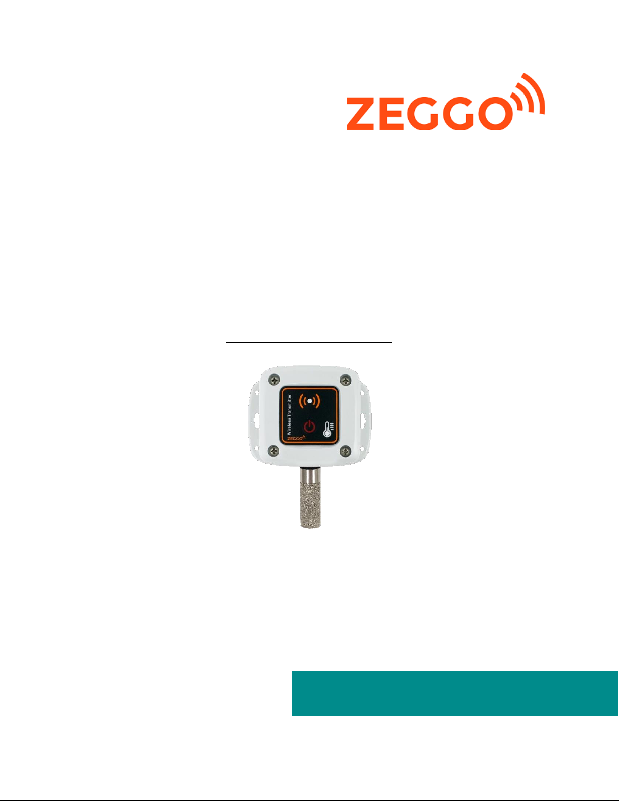
Zeggo THA C1Z1 User manual

ZEGGO THA_C1Z1
REV. 1 03/19
1
Future Integrated Data Evaluation
Wireless Humidity and
Temperature Transmitter
Model: THA_C1Z1
USER MANUAL

ZEGGO THA_C1Z1
REV. 1 03/19
2
DOCUMENT HISTORY
Release
No.
Date
Revision Description
1
28/03/19
First Release, Humidity Transmitter THA_C1Z1 V1.0
2
16/04/19
System manual updated

ZEGGO THA_C1Z1
REV. 1 03/19
3
Introduction
Thank you for selecting the Zeggo Wireless Humidity and Temperature Transmitter. This device transmits
the humidity and temperature reading wirelessly from remote location to designated gateway for online
monitoring. In this package you will find:
•One Transmitter THA_C1Z1
•One User Manual
This device is ideal for monitoring the temperature of various environment 24/7. The data send to Zeggo
platform to monitor environment humidity and temperature condition and send alert to personal device
when temperature out of preset range.
The temperature transmitter features:
•Secure AES128 IEEE802.15.4 Radio Transmission to Zeggo’s Gateway
•Easy Configuration and Installation
•>2 Years of Battery Life
•Internal storage to store during network failure
•Programmable sampling interval: 1min, 5min, 10min, 15min, 30min
Specification
Battery
3.6V 4400mAh lithium battery, “AA” size
Battery Life
6 months to 3 Years. Depending on environment condition
and transmission time setting. (Innoflex is not responsible for
the specific battery life.)
Radio Frequency
ISM 2.4Ghz
Range of Transmission
Up to 60m Indoor and up to 300m under line of sight
(Depends on site condition)
Operating Condition
-40°C to 70°C
Sensor Type
Digital CMOS Sensor Chip
Measurement Range
Temperature (-40 to 70°C); Humidity (0 to 100%RH)
Accuracy
±0.3 °C (at 0 to 65°C); others ±1°C
±3%RH (10 to 90%RH, others ±5 %RH)
Category of resistance to heat
and fire
UL94-V0 (Case)
Size
3.6” x 4.3” x 1.7”

ZEGGO THA_C1Z1
REV. 1 03/19
4
Product Description
Figure 1: THA_C1Z1 Description
Product Introduction
THA_C1Z1 Temperature Transmitter functions as a remote transmitting device. A gateway with internet
access must within the range that the sensor reading can successful transmit over to the gateway. The
radio range between transmitter and gateway varies significantly based on the site environment and
surrounding objects (metal walls, furniture etc.). The compatible model of Zeggo’s gateway for THA_C1Z1
is:
•Zeggo Gateway, GWA_12Z1
Startup Operation
Temperature transmitter equipped with full battery at the time of delivery. It is always a good practice to
check that the device is ALIVE prior to the installation by turn ON/ OFF the device. By pressing and holding
the button for an interval, blinking and colour of status LED will indicate current ON/OFF status.
Table 1: Turn On And Off Operation
Button Press and Hold Period
Status LED Behaviour
ON/OFF Status
> 3 second
Flashing of Green LED
Turn ON
> 5 second
Light up Red LED
Turn OFF/ Go into Sleep
A signal will send out to the gateway immediately after turned on accompany with blinking of LED
indicating the operation status. Green LED indicated the data reading is successfully sent and received
by gateway. On the other hand, flash of Red LED shows a transmission failure or sensor fault.
Configuration Button (ON/OFF)
Sensor Probe(Metal type)
Status LED (Green/ Red Bicolour)
Flange

ZEGGO THA_C1Z1
REV. 1 03/19
5
During start up, the device sent out a signal every 6 second and there is a total of 6 start up transmission
cycle. It is useful to check the transmission status during starting period (about 36 seconds) before device
going into normal operation which has longer transmission interval. Start up operation can trigger
repeatedly every turning on device from off state.
Mounting
Avoid placing the device close to a metal object that may affect the transmission range. Depends on
installation location, devices can be installed by using screw (nominative diameter which is less than
5mm and not smaller than 3mm are recommended) on both flange of the enclosure. For surface
mounting, surface shall be cleaned to ensure free of grease, water and dust.
Configuration
Binding & Sending Interval Setting
Device will enter configuration mode from special sequence button press and hold.
i) Make sure the device is in OFF state and wait for about 4 second.
ii) Press the ON/OFF/configuration button for 4 times. (Interval must less than 2 secs)
iii) Press and hold the button for the 5th attempt.
The status LED will blink GREEN and RED alternately upon successful enter configuration mode. If the
status LED blink GREEN LED only, it fails to enter configuration but goes into normal ON mode. Kindly
follow the steps again for another attempt. Once successfully enter the configuration mode, device will
receive binding command. It will automatically search for the nearest gateway and binding to it after
exit and turn on the device. Communication will begin upon a successful binding.
During configuration mode, 10 secs timeout is implemented if no input is received. Each press and release
of button will go a step in the sending interval setting as below:
Table 2: Sending Interval Setting
Green Status LED Number of Blinking Times
Sending Interval Setting
1
1 min
2
5 mins
3
10 mins
4
15 mins
5
30 mins
Once the correct setting has been set, leave it for about 10 seconds to exit the configuration mode. The
device will back into OFF state. It will bind to nearest gateway and follows the transmission interval setting
after turned ON (after startup cycle finished).

ZEGGO THA_C1Z1
REV. 1 03/19
6
Configuration (Admin)
These are the configurations that could be accessed by Zeggo’s technician only.
Reset Memory/ Time, Reset Battery
This feature enables the zero calibrate the ADC, clear the internal storage and reset stored time in the
device memory.
i) Unplug the sensor.
ii) Turn the slide switch in OFF position.
iii) Press and hold the reset button on the PCB Board.
iv) Turn the slide switch in ON Position.
v) Wait for a preset of time and observe the status LED according to Table.
vi) Release the reset button.
Table 3: Configurations by Admin
Time Holding Reset Button
Status LED Indication
Configuration Made
5 Secs
Green LED Lighted Up
Zero Calibration
15 secs
Alternate Green Red (Slow)
Clear Internal Memory, Reset
Time
30 secs
Alternate Green Red (Fast)
Reset Battery Counter/
Percentage
Software Calibration
Device will enter configuration mode from special sequence button press and hold.
i) Make sure the device is in OFF state and wait for about 4 second.
ii) Press the ON/OFF/configuration button for 7 times (For negative calibration)/ 9 times (For positive
calibration). (Interval must less than 2 secs)
iii) Press and hold the button for the next attempt.
The status LED will blink GREEN and RED alternately upon successful enter configuration mode. If the
status LED blink GREEN LED only, it fails to enter configuration but goes into normal ON mode. Kindly
follow the steps again for another attempt.
During configuration mode, 10 secs timeout is implemented if no input is received. Each press and release
of button will go a step in the sending interval setting as below:

ZEGGO THA_C1Z1
REV. 1 03/19
7
Table 4: Software Temperature Calibration
Status LED Number of Blinking Times
Software Calibration Value (oC)
1 times RED
-0.5
2 times RED
-1.0
3 times RED
-1.5
4 times RED
-2.0
5 times RED
-2.5
1 times GREEN
+0.5
2 times GREEN
+1.0
3 times GREEN
+1.5
4 times GREEN
+2.0
5 times GREEN
+2.5
Once the correct setting has been set, leave it for about 10 seconds to exit the configuration mode. The
device will back into OFF state. It will proper calibrated after turned ON.
Internal Memory Backup
In the event when signal failed to send to a gateway, the temperature data stores in the internal
memory. These backup data will send again to gateway after network recovery. The maximum backup
period depends on sending interval setting.
Table 5: Maximum Backup Period
Transmission Interval
Maximum Backup Period*
1 min
7 days
5 mins
37 days
10 mins
75 days
15 mins
113 days
30 mins
227 days
*In condition all the previous backup data has been successfully send out from the initial.
Battery Level & Signal Level
Table 6: Device Battery Life
Transmission Interval
Device Battery Life
1 min
6 months
5 mins
2 years
10 mins
3 years
15 mins
3 years
30 mins
3 years

ZEGGO THA_C1Z1
REV. 1 03/19
8
The battery life is purely indicative as it mainly depends on transmission interval setting, installation
environment condition and quality of wireless connection. If the device fails to communicate with the
gateway, it will consume more power to search the gateway and restore connection.
Both the battery level and signal level of the device can be view from Zeggo’s portal. It is recommended
to replace the battery if battery level is less than 20%. The suggested signal percentage for a stable
connection is >40% to take care the moving object or addition of object in between signal path.
Information Regarding Product Disposal
This product contains Lithium Thionyl Chloride Battery. There are a fire, explosion, and severe burn
hazard. Do not burn or expose the battery to high temperatures. Do not recharge, crush, disassemble, or
expose the contents to water. Properly dispose of used batteries according in accordance with applicable
regulations in country. A disposal service could offer upon request.

ZEGGO THA_C1Z1
REV. 1 03/19
9
Limited Warranty & Limitation of Liability
Innoflex Pte Ltd warrants that the hardware of product will be free from material defects in workmanship
and materials under normal use in accordance with Innoflex instructions and directions from the purchase
date of the product, for the period (“Warranty Period”), except as otherwise stated herein.
• Hardware: One (1) year
At its option, Innoflex will repair or replace at no charge the product which proves to be defective within
such warranty period. The warranty extends only to the original buyer or end-user customer of a Innoflex
authorized reseller, and does not apply to fuses, disposable batteries or to any other product which, in
Innoflex’s opinion, has been misused, altered, neglected, or damaged by accident or abnormal conditions
of operation or handling. Any replaced or repaired products or parts carry a ninety (90) day warranty or
the remainder of the initial warranty period, whichever is longer.
INNOFLEX MAKES NO WARRANTIES, EXPRESSED OR IMPLIED, INCLUDING THE IMPLIED WARRANTIES OF
MERCHANTABILITY AND FITNESS FOR A PARTICULAR PURPOSE WITH RESPECT TO THIS MANUAL AND, IN
NO EVENT SHALL INNOFLEX BE LIABLE UNDER ANY CONTRACT, NEGLIGENCE, STRICT LIABILITY OR OTHER
LEGAL OR EQUITABLE THEORY FOR ANY LOSS OF USE OF THE PRODUCT, INCONVENIENCE OR DAMAGES
OF ANY CHARACTER, WHETHER DIRECT, SPECIAL, INCIDENTAL OR CONSEQUENTIAL (INCLUDING, BUT NOT
LIMITED TO, DAMAGES FOR LOSS OF GOODWILL, LOSS OF REVENUE OR PROFIT, FAILURE OF OTHER
EQUIPMENT TO WHICH PRODUCT IS CONNECTED WITH) RESULTING FROM THE SUE OF PRODUCT,
RELATING TO WARRANTY SERVICE, OR ARISING OUT OF ANY BEACH OF THIS LIMITED WARRANTY, EVEN
IF INNOFLEX HAS BEEN ADVISED OF THE POSSIBILITY OF SUCH DAMAGES. THE SOLE REMEDY FOR A
BREACH OF THE FOREGOING LIMITED WARRANTY IS REPAIR, REPLACEMENT OR REFUND OF THE
DEFECTIVE OR NONCONFORMING PRODUCT. THE MAXIMUM LIABILITY OF INNOFLEX UNDER THIS
WARRANTY IS LIMITED TO THE PURCHASE PRICE OF THE PRODUCT COVERED BY THE WARRANTY. THE
FOREGOING EXPRESS WRITTEN WARRANTIES AND REMEDIES ARE EXCLUSIVE AND ARE IN LIEU OF ANY
OTHER WARRANTIES OR REMEDIES, EXPRESS, IMPLIED OR STATUTORY.
All rights of the attached documents belong to Innoflex Pte Ltd. It is prohibited to use, duplicate and/ or
arrange a part of whole of the attached documents without prior written to/ permission of Innoflex Pte
Ltd. Specification, software, design and other contents outlined in the attached documents are accurately
describe at the time of publication and subject to change without notice in the interest of constant
product development. All registered trademarks, product names and logos mentioned herein or for
products being used are the property of Innoflex Pte Ltd or of their respective owners. The products are
not designed nor intended for use in safety-critical, automotive, military or aerospace applications or
environment unless specifically designated by Innoflex Pte Ltd.
Innoflex Pte Ltd
3015 Ubi Road 1,#02-218 , 408704 • Singapore.
Phone: +65 6749 1575
Email: support@innoflex.com.sg
www.zeggo.com.sg
Subject to change without notice. • Copyright © 2017 • Printed in Singapore
Table of contents
Other Zeggo Transmitter manuals