Matrix™ 1024 Installation
Matrix™ 1024 Installation
Matrix overview
The Matrix is a network management switch that can filter, de-
duplicate, trim and time stamp inbound traffic and replicate, aggregate,
or load-balance outbound traffic before sending it to your network and
security monitoring tools.
License The device is pre-licensed at the factory. The
license enables ports in blocks of four starting at
port 1. It also indicates the number of blocks that
are 10 Gb-capable. If you have eight ports licensed,
you may only use ports 1-8. Ports 9-24 remain dark
and unusable even if you insert an SFP module. If
you need more ports or blocks of 10 Gb, you can
request a license upgrade.
IP Address 192.168.1.10. Must use HTTPS in a web browser or
SSH. HTTP will fail.
Default User/
password
admin/admin
Self-signed
certificate
VIAVI uses a self-signed certificate. When
connecting to the device, your web browser may
issue a warning about the site being "untrusted"
or that there is a problem with the "security
certificate." This is a harmless message that may
be ignored. You see that message because the
site uses a self-signed certificate. See your web
browser's documentation for adding the IP address
as a trusted source.
How to connect Matrix to your network
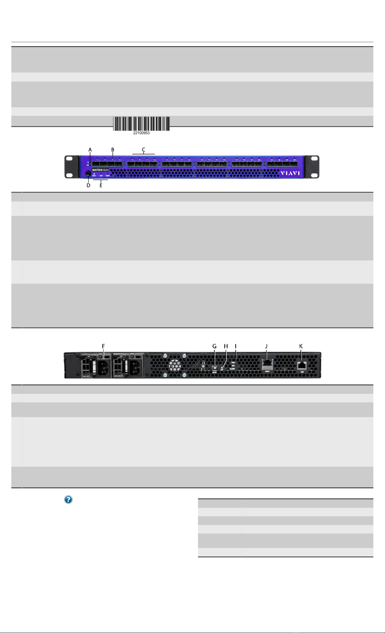
Before you can configure or use the Matrix, you must complete
the basic installation by connecting power cables and inserting SFP
modules. (See images on other side.)
1. Insert the two power cables (F).
2. Connect an RJ-45 Ethernet cable to the MGMT port (J).
3. Insert the SFP or SFP+ modules into the ports (C).
4. Connect the appropriate network cables to the SFP or SFP+
modules.
5. Press the Power switch (D) on the front of the device.
How to set IPv4 network settings
The Matrix must be added to your network like other devices. Use the
network settings page to set IPv4 settings for IP address and netmask,
gateway, host name, and more.
The Matrix is an active network device (unlike a typical optical TAP
for instance). The Matrix has a hardware address and requires an IPv4
address assignment to join your network. However, IPv6 can optionally
be enabled and used side-by-side with IPv4—the matrix supports
native dual-stack. Address assignments can be manually configured or
dynamically assigned using DHCP or DHCPv6.
1. Starting in the dashboard, click System.
2. Click Network.
3. In Hostname, type a host name for the Matrix.
4. (Optional) Use DHCP for address assignments:
a. Select DHCP.
b. Click Save.
5. In IP Address, type the IP address the Matrix must use.
6. In Netmask, type the full netmask associated with the chosen IP
address.
7. In Gateway, type the IP address of the gateway the Matrix must
use.
8. In DNS Address 1, type the IP address of a DNS server.
9. (Optional) In DNS Address 2, type the IP address of a DNS server.
10. Click Save.
How to change the administrator password
The default admin user has full permissions and cannot be deleted. For
these reasons, change the admin password as soon as possible.
The admin user in the Matrix is similar to the "root" user in other
products.
To change the administrator password:
1. Starting in the dashboard, click System.
2. Click Authentication.
3. Click the Users tab.
4. Search for and click the admin user to select it.
5. In the menu bar, click Edit.
6. In the Set Password box, type a password.
7. In the Confirm Password box, re-type the same password.
8. Click OK.
How to add users
You can add users so they have the ability to authenticate and log in.
When adding a user, be aware that each user of the Matrix must be
assigned group membership. You are able to assign group membership
during the creation of the user.
To add a user:
1. Starting in the dashboard, click System.
2. Click Authentication.
3. Click the Users tab.
4. Click Add.
5. Configure the settings of the user.
How to set the system time and date
You can set or change how the current date and time is acquired. Doing
so ensures log events have correct dates and times and that packet
trailer timestamps are accurate.
The Matrix must acquire its time and date from a clock source.
To set which clock source acquires the system time and date:
1. Starting in the dashboard, click System.
2. Click General.
3. In the Clock Source list under System Time Configuration, click a
clock source.
If you select NTP, you must type an NTP server IP address in Server
1.
4. Click Save.
How to upgrade the firmware
You can upgrade the firmware to ensure maximum performance and
stability of the system, and to update the documentation and tooltips.
Prerequisite(s):
VIAVI continually releases improvements through firmware updates.
Ensure you have the latest firmware by downloading it from
http://update.viavisolutions.com/pub/Matrix/1024/firmware/
matrix1024-1.0.15.0.fw.
Firmware upgrades consist of two simultaneous updates:
1. An update to the user interface
2. An update to the switch board
Both updates are performed simultaneously during a single firmware
upgrade.
♦Network traffic continues processing during the upgrade,
except for a momentary interruption at the end of the switch
board update which takes approximately 20 minutes.
♦The user interface is unavailable for approximately 5 minutes
while it is updating.
♦The overall process may take up to 30 minutes to complete.
1. Starting in the dashboard, click System.
2. Click Firmware.
3. Click Browse.
4. Browse to a firmware file using the dialog box and click Open.
5. Click Upload.
The file uploads in the background, so do not close your browser.
After the upload is complete, the file is verified and unpacked.
6. Click Upgrade.
How to set a user authentication scheme
You can leverage your organization's existing authentication service in
the Matrix. Set a user authentication scheme to command your Active
Directory, LDAP, TACACS+, or other server, to perform authentication
duties for the Matrix.
Most organizations use some type of server for user authentication.
One of these authentication servers can be used by the Matrix to
authenticate its users.
1. Starting in the dashboard, click System.
2. Click Authentication.
3. In the Authentication Scheme list, click an authentication scheme.
4. Provide the information needed to connect to the authentication
service.
Tooltips are available by pausing your pointer on each option, and
the boxes highlight any missing details after you click Accept.
5. Click Save.