VIBIA Brisa 4630 User manual

4630. Net Weight / Peso Neto / Netto-Gewicht 2 Kg
1 x LED 3W 700mA
50 Hz
Class I. Product with an additional protection cable (grounds).
Clase I. Aparato con un cable protector adicional (toma de tierra).
Klasse I. Apparat mit zusätzlichen Schutzleiter (Erdkabel).
Dust-tight product. Protected against water trickles.
Producto totalmente estanco al polvo. Protegido contra los chorros de
agua.
Staubdicht. Schutz gegen das Eindringen von Strahlwasser.
Product that CAN be in contact with normally-flammable materials (wood or
others).
Está permitido que el producto marcado con este simbolo esté en contacto
con materiales normalmente inflamables (maderas u otros).
Es ist erlaubt Produkte mit diesem Etikett auf normal entflammbaren
Oberflächen (Holz usw.) zu montieren.
Alternating current
Corriente alterna
Wechselstrom
Before assembling and installing this product, carefully
read the following:
Antes de proceder al montaje e instalación de esta
luminaria, leer detenidamente las siguientes
consideraciones.
Bevor Sie mit der Montage dieser Leuchte beginnen,
sollten Sie die folgenden Hinweise in aller Ruhe lesen und
berücksichtigen.
-Switch of the mains before installing the lamp. -Desconectar el suministro eléctrico antes de proceder a la
instalación de la luminaria.
- Schalten Sie vor dem elektrischen Anschluss den Strom ab.
-If the steel cable or the power cord of this lamp is damaged, it
must be replaced only by the manufacturer or their technical
service or by a person capacitated to this effect to avoid any
risk.
-Si el cable flexible o cordón de esta luminaria está dañado,
deberá sustituirse exclusivamente por el fabricante o su
servicio técnico, o por una persona con cualificación
equivalente con objeto de evitar cualquier riesgo
- Wenn das Kabel dieser Leuchte beschädigt werden sollte,
muss es ausgetauscht werden. Dies darf ausschliesslich nur
durch den Fabrikanten, seinem Kundendienst oder einer
hierfür qualifizierten Person geschehen, um jegliche Gefahr
ausschliessen zu können.
-We recommend reading the manual before installaing the
lamp. Keep this instructions for future reference.
-Recomendamos leer el manual antes de iniciar la instalación
de la luminaria. Guardar estas instrucciones para futuras
consultas.
-Wir empfehlen vor Montagebeginn die Anleitung zu lesen.
Bewahren Sie die Anleitung für etwaige zukünftige Fragen auf.
Caution / Precaución / Vorsicht
EN
D
ES
SUPPLIED MATERIAL MATERIAL SUMINISTRADO
GELIEFERTES MATERIAL
1.
TECHNICAL SPECIFICATIONS ESPECIFICACIONES
TÉCNICAS TECHNISCHE DATEN
Brisa
Design by Lievore, Altherr, Molina
ASSEMBLY INSTRUCTIONS
INSTRUCCIONES DE MONTAJE
MONTAGEANLEITUNG
4630
1
Tube ofthermal grease / Tubo silicona térmica / Röhrchen mit Wärmeleitpaste 1 un.
2
Allen key / Llave allen / Inbusschlüssel 1 un.
3
Screws / Tornillos / Schrauben 3 un.
4
Lamp structure / Estructura luminaria / Leuchten-Struktur 1 un.
2.
3.
4.

ASSEMBLY INSTRUCTIONS INSTRUCCIONES DE MONTAJE MONTAGEANLEITUNG
EN
ES
IMPORTANT NOTICE:
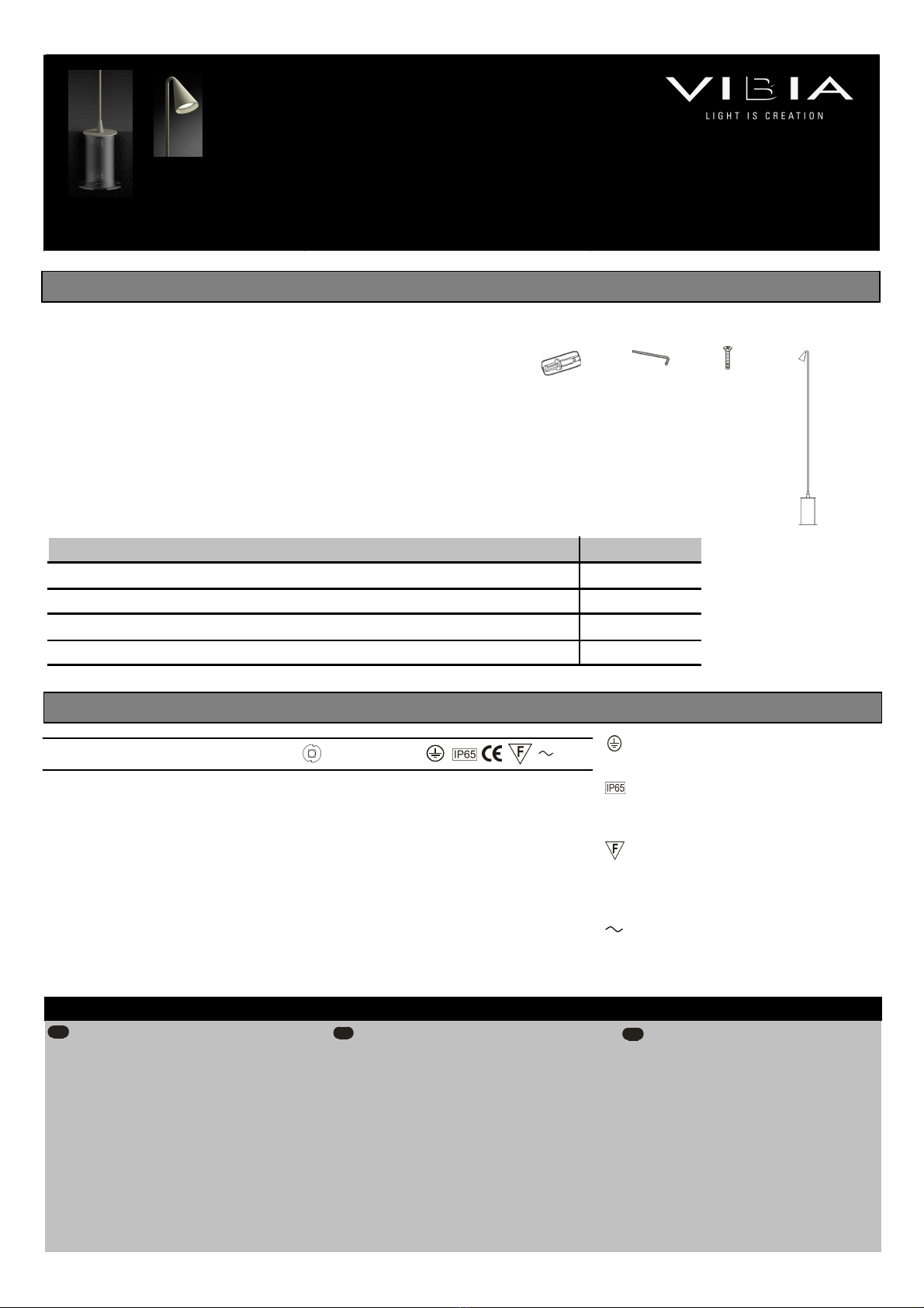
Switch off the mains before installing the lamp.
1.
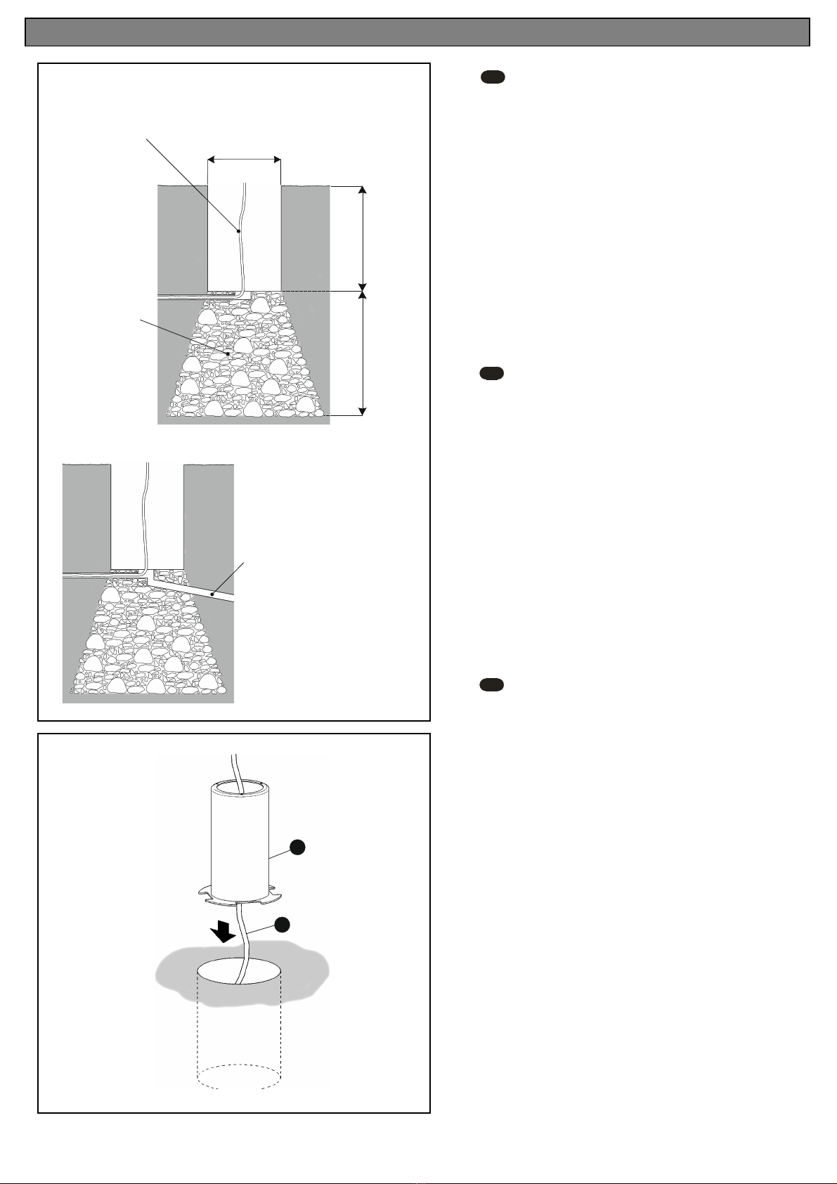
Make a hole in the ground of Ø13.5cm and 18.5cm deep to set the
casing (A) into, and provide a gravel drainage system 20-30cm deep if the
ground is sandy. If the lamp is to be set into concrete, provide for the most
suitable drainage system.
IMPORTANT: Carry out a trial by filling the hole with water and waiting 30
minutes; if the water has not drained away completely by this time, fit an
extra drainage system.
2. Insert the casing (A) in the resulting hole, running the power cable (B)
through inside it. Enough length of cable must stick out above the ground to
make the power connection.
NOTE: Before filling in with cement, make sure the threaded holes in the
top are in the right position for the light fitting to face in the desired direction
once installed.
IMPORTANTE:
Desconectar el suministro eléctrico antes de realizar la instalación de
la luminaria.
D
WICHTIG:
Schalten Sie den Strom ab. bevor Sie die Leuchtenmontage
realisieren.
1.
Realizar un orificio en el suelo de Ø13,5 cm. y 18,5 cm. de profundidad
para poder empotrar el cuerpo (A), dejando preparado debajo un sistema de
drenaje de entre 20 y 30 cm. con base de grava, si el terreno es arenoso. En
caso de que se empotre en hormigón, prever el sistema de drenaje más
adecuado.
IMPORTANTE: Realizar la prueba de llenar de agua el orificio y esperar 30
minutos, si después de este tiempo no se ha evacuado todo el agua, hacer un
sistema de drenaje complementario.
2. Introducir el cuerpo (A) en el agujero realizado pasando a través de su
interior la manguera de conexión eléctrica (B). Debe sobresalir del suelo la
longitud necesaria de manguera para facilitar la conexión eléctrica.
NOTA: Antes de rellenar de pasta asegurarse que la posición de los tres
taladros roscados superiores queden bien orientados para que la luminaria
una vez instalada quede en la dirección deseada.
1.
Fertigen Sie zum Versenken des Einbautopfes (A) im Boden eine
Öffnung von Ø 13,5 cm und 18,5 cm Tiefe an, unterhalb muss sich bei
sandigem Boden ein aus Kies bestehendes Entwässerungssystem von 20
bis 30 cm befinden. WICHTIG: Machen Sie die Probe, indem Sie die
Öffnung mit Wasser füllen und 30 Minuten warten. Ist das Wasser nach
dieser Zeit nicht vollständig abgelaufen, muss ein zusätzliches
Entwässerungssystem angelegt werden. Beim Einbau in Beton ein
angemessenes Entwässerungssystem auswählen.
2. Setzen Sie nun den Einbautopf (A) – zusammen mit dem sich in seinem
Innern befindenden Stromschlauch (B) – in die angefertigte Öffnung ein. Der
Stromschlauch muss hierbei soweit über den Boden hinausragen, dass
problemlos der elektrische Anschluss durchgeführt werden kann.
HINWEIS: Vergewissern Sie sich vor dem Auftragen der Spachtelmasse,
dass die oberen Gewindebohrungen richtig ausgerichtet sind, damit die
Leuchte nach der Installation auch wie gewünscht sitzt.
2
A
B
Ø13,5 cm.
18,5 cm.
20 - 30 cm.
-Mains power cable
-Kabel Ihrer Elektroinstallation
-Cable de su instalación eléctrica
-Gravel for drainage
-Entwässerungskies
-Grava de drenaje
1
-Extra drain pipe
-zusätzliches Entwässerungsrohr
-Tubo de drenaje complementario

3
EN
ES
3.
Fill in the hole with cement until it is flush with the ground and make the
electrical connection:
One: Remove the 4 screws from the wiring box and open up the cover (C).
Two: Loosen the cable gland (D) in order to insert the cable (B) into the wiring
box.
Three: Make the electrical connection, live+neutral, in the box (E) plus earth at
the terminal (F).
IMPORTANT: This model is ready for direct connection to an IP 65-class power
point. The cable used must be H05 RN-F <HAR> or better rubber, between 7
and 12mm in diameter.
4. After making all the connections, tighten up the cable gland (D) firmly once
more. You are advised to seal where the mains power cable enters the box as
shown in the drawing, using the syringe of thermal silicon grease supplied (G).
5. Fit the cover (C) with the 4 screws and remember to tighten the cable gland to
ensure it is sealed.
D
3.
Füllen Sie nun die Öffnung mit Spachtelmasse auf, sodass sie bündig mit der
Oberfläche abschließt und führen Sie den Stromanschluss wie folgt durch:
Erstens: Lösen Sie vom Klemmenkasten die 4 Schrauben und entfernen Sie den
Deckel (C).
Zweitens: Lockern Sie die Kabelklemmen (D), um dann das Kabel (B) einzuführen
und die Verbindung im Klemmenkasten herzustellen.
Drittens: Führen Sie den Anschluss ans Stromnetz durch, schließen Sie hierzu
Phase + Null-Leiter im Kasten (E) und das Erdungskabel an die Klemme (F) an.
WICHTIG: Das Modell ist für den direkten Anschluss an eine Steckdose mit
Schutzgrad IP 65 konzipiert. Das verwendete Stromkabel muss mindestens eine
Gummiummantelung des Typs H05 RN-F <HAR> mit einem Durchmesser
zwischen 7 und 12 mm aufweisen.
4. Nachdem alle Kabel angeschlossen sind, die Kabelklemmen (D) wieder fest
zudrücken. Die Kabelöffnung sollte – wie auf der Abbildung zu sehen – mithilfe der
im Lieferumfang enthaltenen Wärmeleitpastenspritze (G) versiegelt werden.
5. Bringen Sie den Deckel (C) wieder mithilfe der 4 Schrauben an.
B
F
D
C
E
ASSEMBLY INSTRUCTIONS INSTRUCCIONE
S DE MONTAJE MONTAGEANLEITUNG
3.
Rellenar con pasta el hueco hasta enrasar con la superficie y realizar la
conexión eléctrica:
Primero: Desmontar los 4 tornillos de la caja de conexión para extraer la tapa
(C).
Segundo: Aflojar el prensacables (D) para introducir el cable (B) en la caja de
conexión.
Tercero: Realizar la conexión eléctrica, fase+neutro en la caja (E) y toma tierra
en el terminal (F).
IMPORTANTE: El modelo va preparado para ser conectado directamente a una
toma de corriente cumpliendo un IP 65. El cable utilizado debe ser de goma o
superior tipo H05 RN-F <HAR> de entre 7 y 12 mm. de diámetro.
4. Una vez realizadas todas las conexiones, volver a apretar fuertemente el
prensacables (D). Se recomienda sellar la entrada del cable de su instalación
por la parte interior de la caja de conexiones, según se ve en el dibujo, con la
jeringuilla de silicona térmica suministrada (G).
5. Montar la tapa (C) asegurándola con los 4 tornillos.
D
G
C
4
5

ASSEMBLY INSTRUCTIONS INSTRUCCIONES DE MONTAJE
MONTAGEANLEITUNG
-Use a slightly-wet cotton cloth for cleaning.
-Para limpiar la luminaria, usar un paño de algodón
ligeramente humedecido en agua.
-Zur Reinigung der Leuchte nutzen Sie einen leicht
angefeuchteten Baumwoll-Lappen.
-In case of malfunction or damage, please contact
the retailer who sold the lamp.
-En caso de avería o incidente con la luminaria,
contactar directamente con el establecimiento en
que se adquirio.
-Im Falle des Ausfalls oder einer Fehlfunktion der
Leuchte setzen Sie sich direkt mit dem Unternehmen in
Verbindung bei dem Sie die Leuchte bezogen haben.
Maintenance / Mantenimiento / Instandhaltung
EN DES
6
.
Insert the sealed wiring box and fit the cables inside the casing set into the
ground (A).
7. Put in the three screws (H) supplied to secure the fitting.
8. The rod can be rotated as shown.
EN
ES
D
GRUPO T DIFFUSION S.A. Barcelona, 72-74. 08820 El Prat de Llobregat (Barcelona - Spain)
Nacional Tel 934 796 970. Fax 934 796 973. Internacional Tel +34 934 796 971. Fax +34 934 782 026
www.vibia.com grupo-t@grupo-t.com
6
.
Introducir la caja de conexiones cerrada y acomodar los cables en el cuerpo
empotrado (A).
7. Montar los tres tornillos suministrados (H) para asegurar el conjunto
8. La varilla ofrece la posibilidad del movimiento de rotación según se indica.
6
.
Führen Sie den verschlossenen Klemmenkasten in den Einbautopf ein (A)
und verlegen Sie die Kabel.
7. Befestigen Sie zum sicheren Halt der Leuchteneinheit die drei im
Lieferumfang enthaltenen Schrauben (H).
8. Mittels Drehstab kann die Leuchte wie angezeigt gedreht werden.
Rotation center
Centro de rotación
Drehzentrum
360º
7
8
A
6
H
Other VIBIA Landscape Lighting manuals
Popular Landscape Lighting manuals by other brands

COLORKINETICS
COLORKINETICS Vaya Flood MP G3 installation instructions

HAMPTON BAY
HAMPTON BAY HD28784 Use and care guide

COLORKINETICS
COLORKINETICS eW Burst Powercore gen2 installation instructions

LIGMAN
LIGMAN JET 41 installation manual

Woodland
Woodland JUST PLUG JP5956 instructions

Malibu Boats
Malibu Boats CS508P instructions

exhart
exhart 19968-RS Assembly instructions

B-K lighting
B-K lighting MCKINLEY Series STANDARD INSTALLATION

One Stop Gardens
One Stop Gardens 93098 Assembly & operating instructions

Volt
Volt VSM-2408-0-BBZ installation instructions

AMP Lighting
AMP Lighting PAR36 Well Light Installation & maintenance guide

LIVARNO home
LIVARNO home 373232-2104 Operation and safety notes