Table of Contents
Product Description
Operating Principle..........................................................................................1
Software ..........................................................................................................1
Getting Started
Components of the M Series System .............................................................2
PC System Requirements ...............................................................................2
Hardware Installation
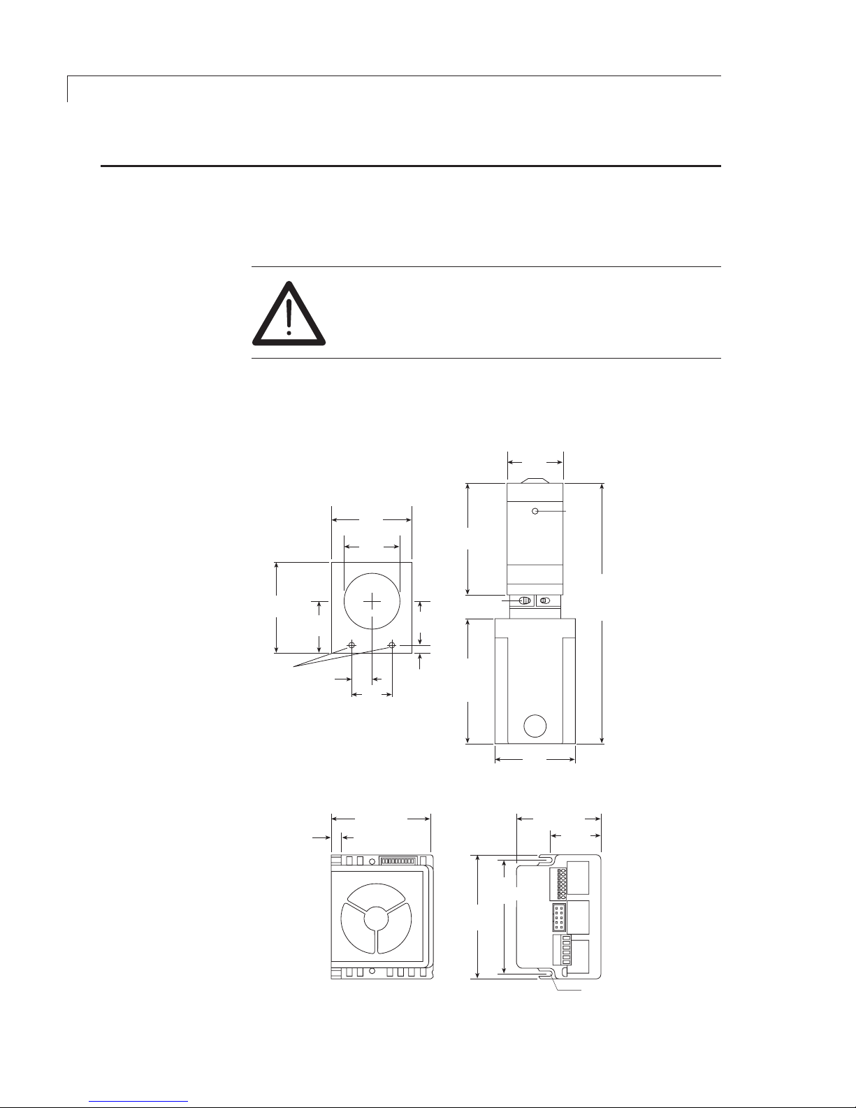
Mounting .........................................................................................................4
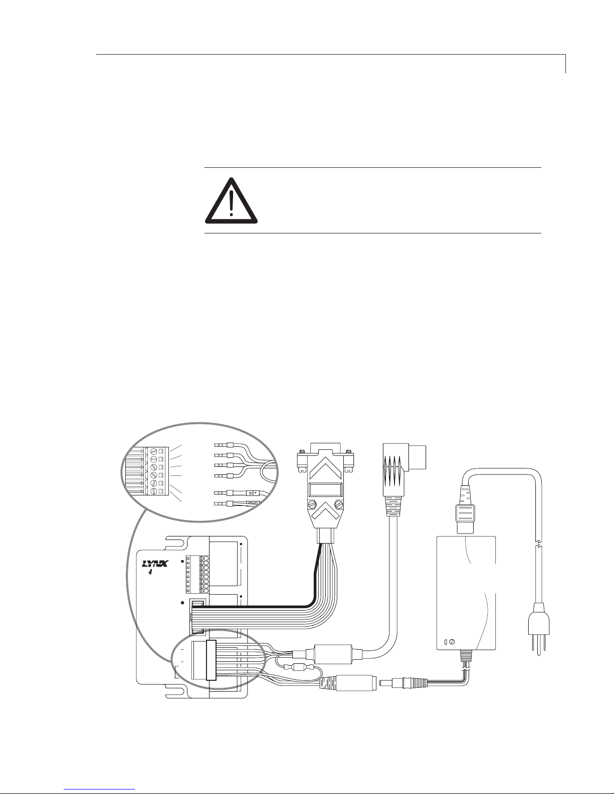
Connections ....................................................................................................5
Initial Setup
M6-LHS Software Installation ..........................................................................6
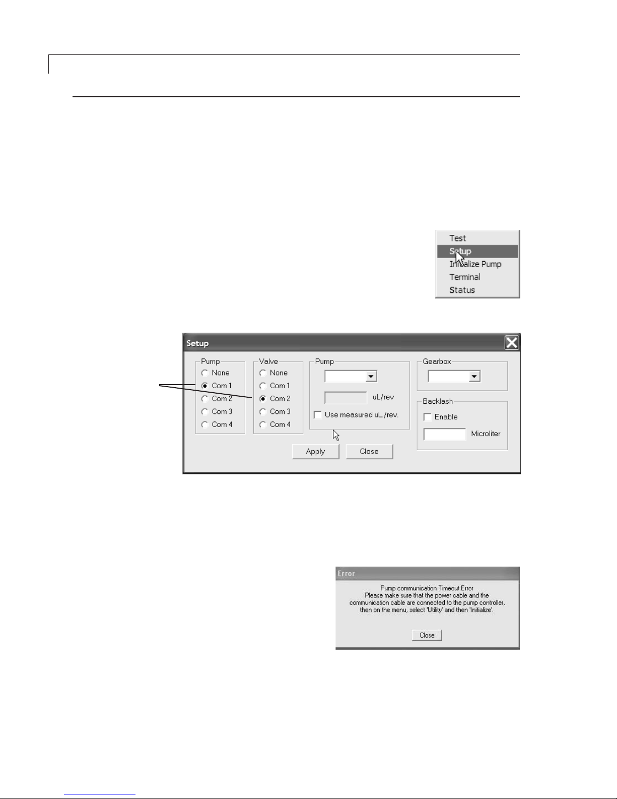
COM Port Assignment ....................................................................................6
Initialization .....................................................................................................6
Selecting Pump and Gearbox Values ..............................................................7
Setting the Backlash and Volume/Revolution Values ......................................7
Priming and Testing the Pump
Tubing Connections (M6 shown) ................................................................... 10
Initial Priming ................................................................................................10
Programming Application Methods
Method Screen Functions .............................................................................12
Example Application Methods
1. Prime System ................................................................................... 14
2. Aspirate and Dispense .....................................................................14
3. Dispense Selected Reagents ...........................................................16
Maintenance
Routine Maintenance ....................................................................................17
Routine Cleaning...........................................................................................17
Chemical Compatibility of Wetted Surfaces
Model M6 ......................................................................................................18
Model M50 ....................................................................................................19
Technical Support ................................................................................................ 20
Returning Pumps for Repair ................................................................................20
Operational and Technical Specifications ............................................................21
Appendix A: MicroLYNX Terminal Section
Terminal Programming Mode ........................................................................22
Appendix B: Setup for Multipump Operation
Connections ..................................................................................................24
Setting the Address of each MicroLYNX .......................................................25
Troubleshooting Party Mode Communications ..............................................28
Warranty ..............................................................................................................30