Vicon Pulsar User manual

Vicon Pulsar Reference Guide
© Copyright 2019–2021 Vicon Motion Systems Limited. All rights reserved.
Vicon Motion Systems Limited reserves the right to make changes to information or specifications in this document without notice.
Companies, names, and data used in examples are fictitious unless otherwise noted. No part of this publication may be reproduced, stored
in a retrieval system, or transmitted in any form or by any means, electronic or mechanical, by photocopying or recording, or otherwise
without the prior written permission of Vicon Motion Systems Ltd.
Vicon® is a registered trademark of Oxford Metrics plc. Vicon Beacon™, Vicon Evoke™, Vicon Lock™, Vicon Lock+™, Vicon Lock Lab™,
Vicon Lock Studio™, Vicon Pulsar™, Vicon Viper™, and Vicon Vue™ are trademarks of Oxford Metrics plc.
VESA® is a registered trademark owned by VESA (www.vesa.org/about-vesa/). Other product and company names herein may be the
trademarks of their respective owners. For full and up-to-date copyright and trademark acknowledgements, visit
https://www.vicon.com/vicon/copyright-information.
Vicon Motion Systems is an Oxford Metrics plc company.
Email: [email protected] Web: http://www.vicon.com
Contents
About this guide 2
Pulsar status light 3
Pulsar operation 5
Pulsar status icons in Evoke 6
Pulsar patterns 10

Vicon Pulsar Product Guide
A RANGE OF LOCATION BASED VR PRODUCTS BY
2
26 July 2021
•
•
•
•
•
About this guide
This guide contains the following information about Pulsars:
About this guideon page 2
Pulsar status lighton page 3
Pulsar operationon page 5
Pulsar status icons in Evokeon page 6
Pulsar patternson page 10

Vicon Pulsar Product Guide
A RANGE OF LOCATION BASED VR PRODUCTS BY
3
26 July 2021
Pulsar status light
In addition to the infrared active marker LEDs that are visible in Vicon
cameras, which are used for tracking, Vicon Pulsars have a status light, to
enable you to recognize their current battery status and pairing/
connection status. The status light comprises three visible LEDs (green,
red, blue). The following table describes the LED states.

Vicon Pulsar Product Guide
A RANGE OF LOCATION BASED VR PRODUCTS BY
4
26 July 2021
LED status Description
Green on Pulsar battery is charging*
Green off (with USB charger
connected)
Pulsar battery is fully charged
Green off (with USB charger
disconnected)
Pulsar battery has charge
(>20%)
Red on Pulsar battery low (<=20%)
Red off Pulsar battery has charge
(>20%)
Blue off Pulsar cannot configure the
radio
Blue on Pulsar connected to Beacon
Blue on-off (slow pulsing) Pulsar paired to a Beacon but
not connected
Blue on-off (fast pulsing) Pulsar not paired with a
Beacon
Red on-off → Blue on-off → Green
on-off
Boot sequence
All on-off (fast pulsing) Pulsar selected in software
All off Pulsar powered down, or
status lights disabled in
software
Red on-off (sequence repeating) Invalid MAC address, pairing
or connection critical failure
* To ensure the charge indication light is visible, the cluster automatically
switches on when plugged into the charger. This also disables power
down via software, and the infrared marker LEDs are switched off.

Vicon Pulsar Product Guide
A RANGE OF LOCATION BASED VR PRODUCTS BY
5
26 July 2021
Pulsar operation
You can use the power button on a Pulsar to perform the following
functions.
To Do this
Turn on aPulsar On a Pulsar that is turned off, give the button a
single short press.
Select the Pulsar in
Evoke
On a Pulsar that is connected, give the button a
single short press.
Turn off a Pulsar On a Pulsar that is turned on, press the button
for 2 seconds.*
Reboot a Pulsar
(retains settings)
On a Pulsar that is turned on, press the button
for 10 seconds.
Un-pair a Pulsar
from Beacon
During the 10-second period after booting only,
double-press the button.*
*Can be disabled in software to prevent accidental use.

Vicon Pulsar Product Guide
A RANGE OF LOCATION BASED VR PRODUCTS BY
6
26 July 2021
Pulsar status icons in Evoke
On the System tab, in the Clusters part of the System tree, Pulsars that
are paired with a connected Beacon are displayed. Adjacent icons
indicate the status of the Pulsars:
The following table describes each of the Pulsar status icons that are
displayed on the System tab in Evoke.

Vicon Pulsar Product Guide
A RANGE OF LOCATION BASED VR PRODUCTS BY
7
26 July 2021
Icon Meaning
Cyan Connected but not assigned a marker
pattern
Yellow Connected but disabled
Gray Automatically disabled as not linked to a
Smart Object
Green Enabled and assigned a valid marker pattern
Red Disconnected
Yellow battery Battery has low charge (less than 20%)
Red battery Battery has very low charge (less than 10%)
Lightning bolt Plugged in for recharging
Update Evoke has queued or sent new settings to
the Pulsar but has not yet received a
response
No icon Loaded from a previous Evoke session but
not yet connected to this instance of Evoke
Note that the overall system charge is determined by the device with the
lowest charge (unless recharging – see the following note), which is shown
at the top of the Clusters section on the System tab.
The number of devices on charge is also displayed here.

Vicon Pulsar Product Guide
A RANGE OF LOCATION BASED VR PRODUCTS BY
8
26 July 2021
In the following image, the red battery icons to the right of the Pulsar
names indicate that the batteries of the relevant Pulsars are low. The
Lowest Battery Charge indicator shows that the Pulsar with the lowest
charge is almost at 0%, ie, almost fully discharged (a Pulsar whose battery
is fully discharged can no longer communicate with Evoke and
disconnects, and the Lowest Battery Charge indicator then displays the
Pulsar with the next lowest battery).
•
•
Note
The information displayed by the Lowest Battery Charge
indicator depends on the number of devices that are currently
charging:
If some connected devices are currently charging,
they are ignored, as they aren't at risk of running
out of charge.
If all of the connected devices are recharging
(indicated by a lightning bolt icon on the charge
bar), they are included, so that you know when they
are ready for use.

Vicon Pulsar Product Guide
A RANGE OF LOCATION BASED VR PRODUCTS BY
9
26 July 2021
In the following image, the yellow lightning icons to the right of the Pulsar
names indicate that the batteries of the relevant Pulsars are charging (and
the yellow battery icons indicate that the charge is still low). The Lowest
Battery Charge indicator shows that the Pulsar with the lowest charge is
now at 13%.

Vicon Pulsar Product Guide
A RANGE OF LOCATION BASED VR PRODUCTS BY
10
26 July 2021
Pulsar patterns
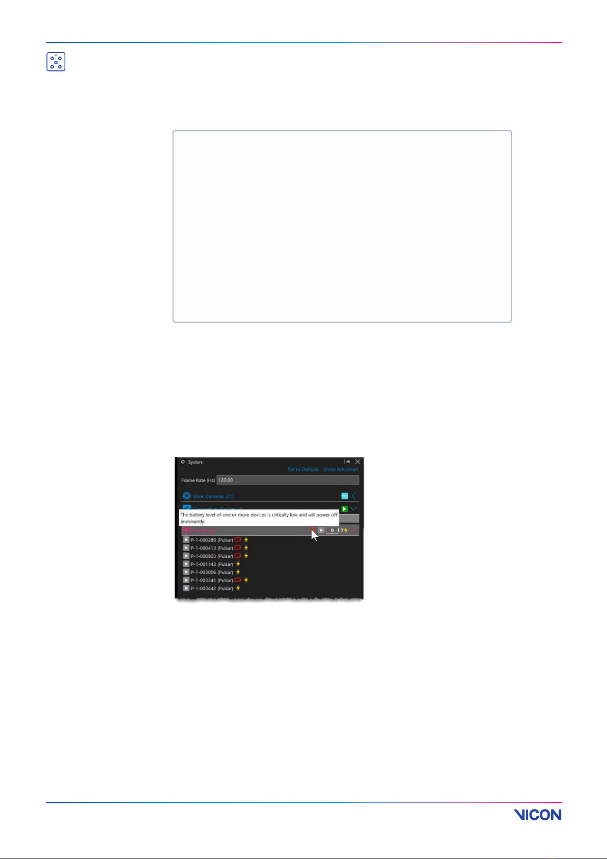
When a Pulsar is first connected, it is displayed in Evoke with a default
pattern of 0, which turns all active markers off. This prevents the Pulsar
from interfering with the tracking of any paired Pulsars thatalready have
patterns set.
If there are noSmart Objects, the Pulsar is Enabledand you can edit the
Marker Patternproperty. (TheMarker Patternproperty is an Advanced
property as usually, patterns are automatically set when you create Smart
Objects.) If anySmart Objects are present, the Marker Pattern property is
read-only and controlled by the associatedSmart Object. If Smart Objects
are present, but a Pulsar has no associatedSmart Object, you cannot
change the pattern or Enabled property for the Pulsar.
TheSmart Cluster Marker Pattern property represents the enabled active
markers as a bit mask. The number value is converted to binary and a set
bit represents an enabled active marker. For example, the
value255is1111 1111 in binary, so all eight markers would be enabled.
The least significant bit (the one on the right) represents the 0 marker in
thePulsar LED circuit order, so the pattern value64(or0100 0000in
binary) represents marker 6 and would result in the single marker below
the status lights being enabled.
Important
Under normal circumstances, the patterns for Pulsar active markers are
automatically generated when you create Smart Objects and you don't need
to change them. The following information is provided for troubleshooting
purposes only.

Vicon Pulsar Product Guide
A RANGE OF LOCATION BASED VR PRODUCTS BY
11
26 July 2021
The following Pulsar LED circuit order diagram shows which LED
corresponds to which bit position index.
Tip
To help generate patterns, you can use the Microsoft Windows
10 Calculator app in Programmer mode to convert from binary to
decimal.
Table of contents
Popular Lighting Equipment manuals by other brands

Image Engineering
Image Engineering lightSTUDIO user manual

ML Accessories
ML Accessories FLN10 Installation & maintenance manual

Venue Lighting Effects
Venue Lighting Effects LED PAR 38 user manual

JB-Lighting
JB-Lighting VARYSCAN 4 COMPACT PLUS 575 HMI user manual

CircuPool
CircuPool Universal Series manual

Nicols
Nicols PAR LED 1812 FC Z user manual

Federal Signal Corporation
Federal Signal Corporation QuadraFlare QL64Z3V-LI installation manual

BAYLED
BAYLED LIBRA RGB user manual

Multiblitz
Multiblitz COMPACT plus Instuctions for use

Bowens
Bowens Streamlite 330 Owner's handbook

AS LED Lighting
AS LED Lighting MidPower 050037 Mounting instructions

Lightolier
Lightolier HDB2SLW128 Specification sheet