FUEL
SPECIFICATIONS
VICTA RECOMMENDS
"BP
ZOOM
25"
WHICH IS COLOURED
GREEN
FOR
EASY IDENTIFICA-
TION.
An
acceptable alternative fuel
is
a mixture
of
"BP
EZimix," or an equivalent high grade two-stroke oil,
and regular petrol in a ratio
of
approximately 25:1 (fuel
to
oill.
To obtain the correct
fuel/
oil mixture pour the appropriate
quantity
of
two-stroke oil into a can and
fill
with
petrol (examples:
for
a 5 litre can add 200
mL
of
oil;
for
a 4.2 litre can add 160
mL
of
oill.
Ensure contents are thoroughly mixed.
Note:
Super
may
be
used
if
regular
is
not
available.
Care
must
be
taken
to
ensure
that
all utensils
are
clean and that no
dirt
or
foreign matter
is
permitted
to contaminate the
fuel/oil
during the mixing process.
The
use
of
the fuel mixture specified above is a condition
of
the edger Warranty.
Warning:
-The use
of
car oils (multigrade) in two-stroke engine fuel will reduce engine life.
TO
START
ENGINE
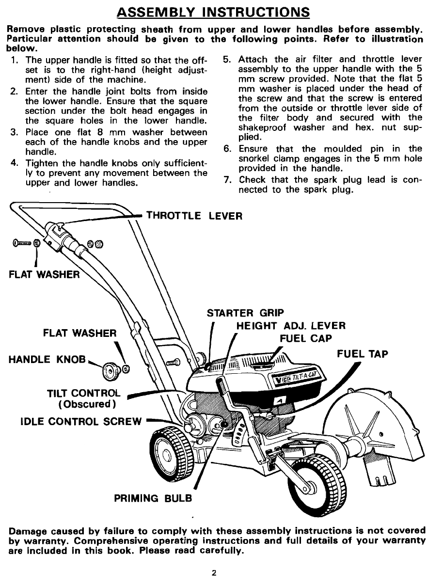
1.
CUTIING
HEIGHT. Before attempting
to
start the engine, the height adjustment should be set in the maximum
height position.
2.
FUEL. Ensure
that
the fuel tank is filled
with
the correct fuel
as
specified.
3.
FUEL TAP. The Victa Edger is normally despatched
from
the
factory
with
the fuel tap in the
"ON"
position.
Check
that
the red tap
is
turned anti-clockwise
to
the position indicated on the label directly above the fuel·tap.
Pause
for
approximately ten (10) seconds
to
allow the fuel
to
reach and fill the carburettor. See Fig. 1 opposite.
4.
THROTILE
CONTROL. The
throttle
control has five (5) settings, STOP, COLD
START,
SLOW, HOT
START
and
GRASSCUTIING.
These positions are marked on the air filter body.
COLD
START
HOT
START
(The first start
of
the day) (Engine has been running before on
that
day)
A.
Set the
throttle
lever
to
"COLD
START."
A.
Set
throttle
lever
to
"HOT
START."
Before attempting
to
start an engine which has been
stored
for
any
length
of
time, move the
throttle
control lever
to
"GRASSCUTIING".
This will
operate an internal cam in the carburettor
to
ensure
that the contacts in the ignition cut
out
switch
have
been freed.
Then set the
throttle
lever
to
"COLD
START".
B.
PRESS BLACK PRIMING BULB
ON
CARBURETIOR
B. DO NOT OPERATE PRIMING
BULB.
ONCE ONLY (See Fig. 2 oppositeL
C.
Stand
to
the right-hand (height adjustment) side
of
C.
PULL STARTER GRIP AS
IN
"COLD
START"
STEP
the edger and brace the machine
by
holding
the
up-
C.
per handle
with
the
left
hand.
With
the
toe
of
the
right
foot
on
the
rear wheel and the heel
on
the
ground
to
steady the edger, take hold
of
the
starter
grip in the right hand and pull
it
smartly towards
you.
While
still holding the starter grip,
allow
the
cord
to
rewind. Repeat pulling action
if
necessary.
After
starting a cold engine,
it
may be necessary
to
allow
it
to
run
for
a
few
seconds,
with
the
throttle
lever remaining in the
"COLD
START"
position, NOTE:
If
the engine does
not
start
first
pull. one
before adjusting the
throttle
lever
to
operating press on
the
priming
bulb
will assist. Leave
position.
throttle
lever in
"HOT
START"
position.
NOTE: STARTING A
NEW
ENGINE
Until your engine
is
fully
run-in the COLD
START
setting
of
the
throttle
lever may
not
be required.
If the engine does
not
start readily, when the COLD
START
instructions are followed,
move
the
THROTILE
LEVER
to
the HOT
START
position and continue pulling starter grip.
It should
not
be necessary
to
press primer bulb again.
3
-) 5
-r