manuals.online logo
Brands
  1. Home
  2. •
  3. Brands
  4. •
  5. Clarke
  6. •
  7. Edger
  8. •
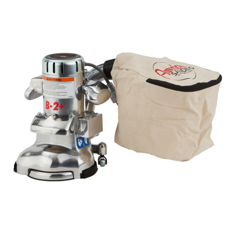
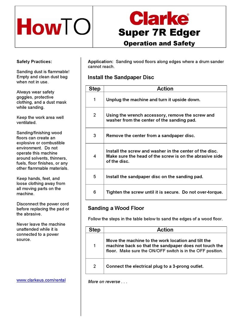
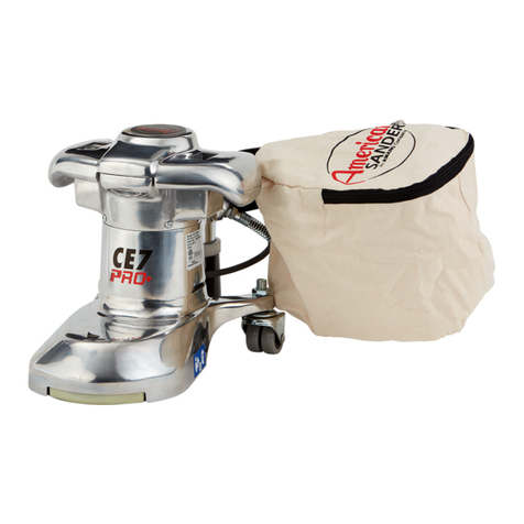
  9. Clarke Super 7R User manual

Clarke Super 7R User manual

56043142 Page 1
MODELS: 07125A, 07126A, 07013A
56043142 Page 2
Switch Replacement
1-Remove the two screws (14) securing the switch cover
2-Remove tape from switch to expose wiring connections
3-Disconnect all wires
4-Remove switch retaining nut (3)
Assembly Hints
Connect the light wires with the incoming power wires on the switch so that the light is on when machine is plugged in
Always retape the switch to prevent shorting between metal objects inside machine
Pigtail Replacement
1-Remove the two screws (14) securing the switch cover
2-Remove tape from switch to expose wiring connections
3-Disconnect the black and white pigtail wires from the switch and the ground wire (35) from the handle housing
4-Remove pigtail and strain relief assembly from Handle housing.
Assembly Hints
Always retape the switch to prevent shorting between metal objects inside machine
Motor Brush Replacement
1-Remove vent plugs (7) and cover plates (5) (6)
2-Disconnect brush shunt wires from the brush block (Fig. 15)
4-Remove the brush springs(38) by pushing in and toward the brush (Fig. 16)
5-Remove brushes (9)
Brush Block Replacement
1-Remove four screws (1) securing handle housing
2-Lift handle housing (36) up (Fig. 17)
3-Disconnect white field wire and black switch wire from brush block
4-Remove four screws (10) securing brush block
Assembly Hints
When reinstalling the handle housing pay special attention not to pinch field wires between the handle and field housing.
Use a small amount of grease to hold the load spring (52) in the handle while assembling.
All four brush springs must be removed and the brushes retracted.
Fig. 15
Fig. 16
Fig. 17
56043142 Page 3
Pad Removal and Replacement
1-Remove paper retaining bolt (84)
2-Wedge dust fan (24) with screwdriver or similar object (Fig. 18)
3-Use spanner wrench (Fig. 19) or large screwdriver and hammer (Fig. 20) to remove pad
Note: if pad turns freely for a couple of turns and then becomes difficult the pinion gear has loosened
instead of the pad and the gear assembly will have to be removed.
4-Remove gear cover assembly by accessing scres through holes in the pad and wall guard
5-Secure the jackshaft (74) in a vise and remove pad (Fig.21)
Note: When replacing the old style steel pad with the new style aluminum the fiber washers between the
pad and lower bearing must be discarded.
Gearbox Removal and Repair
1-Remove pad
2-Remove wall guard (80)
3-Remove three screws (92) from gear cover (78)
4-Remove gear cover assembly
5-Press jackshaft, gear and bearing assembly out of
the cover using the paper retaining screw to prevent damage
to the shaft
6-Press jackshaft (74) out of the gear (76) and bearing (75)
6-Remove snap ring (77) and press bearing out of the cover
Reassembly
1-Press bearing in cover using outer race only
2-Press bearing on jackshaft using the inner race only
3-Install key and press gear on jackshaft
4-Press the jackshaft assembly into the cover assembly by pressing
on the upper end of the jackshaft while supporting the inner race of
the cover bearing
Assembly Hints
The cover (78) has a relief to allow clearance for the pinion gear
and must be installed in the correct position
Pinion Gear Removal
1-Remove the pad
2-Remove the gearbox cover assembly
3-Remove the gear (30) using a 9/16" wrench on the flats of the
pinion gear. NOTE: Pinion gear is left hand threaded
Armature Replacement
1-Remove pad
2-Remove gearbox cover
3-Remove pinion gear
4-Remove motor brush springs
5-Remove light cover and bulb
6-Remove three screws securing the field housing
7-Remove handle and fiels housing assembly (Fig. 22)
8-Lift armature out of the lower housing (Fig.23)

56043142 Page 4
Symptom
Cause
Repair
Sander will not
turn on
No power at outlet
Check and repair power supply or move to
another outlet
Defective cord or plug
Check continuity and replace defective part
Defective switch
Replace switch
Broken wire or bad connection
on brush holder assembly
Repair or replace brush holder assembly
Extremely worn motor brushes
Replace brushes
Defective armature
Replace armature
Excessive arcing
at motor brushes
Brushes worn
Replace brushes
Broken wire or bad connection
on brush holder assembly
Repair or replace brush holder assembly
Worn or defective armature
Replace armature
Sander bounces
on floor when
sanding
Bent or damaged sanding pad
Dress or replace pad
Poor dust pick-up
Dust bag is over 1/3 full
Empty bag
Dust bag is dirty
Shake debris from bag and wash or replace bag
Obstruction in dust tube
Clear dust tube
Castors adjusted improperly
Adjust castors
A Nilfisk-Advance Brand
14600 21st Avenue North
Plymouth, MN 55447-3408
www.clarkeus.com
Phone: 800-253-0367
Fax: 800-825-2753
©2010 Nilfisk-Advance, Inc.

Other manuals for Super 7R

4

This manual suits for next models

3

Other Clarke Edger manuals

Clarke Super 7R Installation and operating manual

Clarke

Clarke Super 7R Installation and operating manual

Clarke American Sanders 07011A User manual

Clarke

Clarke American Sanders 07011A User manual

Clarke Super E User manual

Clarke

Clarke Super E User manual

Clarke Super E User manual

Clarke

Clarke Super E User manual

Clarke 07127A User manual

Clarke

Clarke 07127A User manual

Clarke American B-2 User manual

Clarke

Clarke American B-2 User manual

Clarke 07097A User manual

Clarke

Clarke 07097A User manual

Clarke B2 7" Spinner Edge 07072A User manual

Clarke

Clarke B2 7" Spinner Edge 07072A User manual

Clarke 07170A User manual

Clarke

Clarke 07170A User manual

Clarke American B-2 User manual

Clarke

Clarke American B-2 User manual

Clarke 07127A User manual

Clarke

Clarke 07127A User manual

Popular Edger manuals by other brands

Tanaka Portable Edger TPE-250PF Illustrated parts manual

Tanaka

Tanaka Portable Edger TPE-250PF Illustrated parts manual

TURFCO Edge-R-Rite N2 Operator's manual

TURFCO

TURFCO Edge-R-Rite N2 Operator's manual

Nidek Medical ME 1200 Installation instructions manual

Nidek Medical

Nidek Medical ME 1200 Installation instructions manual

Kobalt KE 2080-06 manual

Kobalt

Kobalt KE 2080-06 manual

Milwaukee M18 FOPH-EA Original instructions

Milwaukee

Milwaukee M18 FOPH-EA Original instructions

Husqvarna 323E, 325E Operator's manual

Husqvarna

Husqvarna 323E, 325E Operator's manual

Briot 4000 user manual

Briot

Briot 4000 user manual

Echo PE-2601 Operator's manual

Echo

Echo PE-2601 Operator's manual

Craftsman CMXGKAM1158708 instruction manual

Craftsman

Craftsman CMXGKAM1158708 instruction manual

Troy-Bilt OEM-290-261 Installation instructions and parts list

Troy-Bilt

Troy-Bilt OEM-290-261 Installation instructions and parts list

Visslo F8 premier Operation manual

Visslo

Visslo F8 premier Operation manual

Powermate King Pro P-WLE-1639-E Illustrate parts book

Powermate

Powermate King Pro P-WLE-1639-E Illustrate parts book

Stihl FC 70 instruction manual

Stihl

Stihl FC 70 instruction manual

Troy-Bilt 554 Operator's manual

Troy-Bilt

Troy-Bilt 554 Operator's manual

Texas Equipment EC1400 user manual

Texas Equipment

Texas Equipment EC1400 user manual

Echo PE-280 Operator's manual

Echo

Echo PE-280 Operator's manual

Craftsman 51157 instruction manual

Craftsman

Craftsman 51157 instruction manual

MTD 245-596-000 owner's guide

MTD

MTD 245-596-000 owner's guide

manuals.online logo
manuals.online logoBrands
  • About & Mission
  • Contact us
  • Privacy Policy
  • Terms and Conditions

Copyright 2025 Manuals.Online. All Rights Reserved.