Victron VE.Bus BMS User manual

Manual
EN
Handleiding
NL
Manuel
FR
Anleitung
DE
Manual
ES
Appendix
VE.Bus BMS


1
EN NL FR DE ES Appendix
1. General Description
Protects each individual cell of a Victron lithium iron phosphate (LiFePO₄) battery
Each individual cell of a LiFePO₄battery must be protected against over voltage, under voltage and over temperature.
Victron LiFePO₄batteries have integrated Balancing, Temperature and Voltage control (acronym: BTV) and connect to the
VE.Bus BMS with two M8 circular connector cord sets.
The BTVs of several batteries can be daisy chained. Please see our LiFePO4 battery documentation for details.
The BMS will:
-shut down or disconnect loads in case of imminent cell under voltage,
-reduce charge current in case of imminent cell overvoltage or over temperature (VE.Bus products, see below), and
-shut down or disconnect battery chargers in case of imminent cell overvoltage or over temperature.
Protects 12V, 24V and 48V systems
Operating voltage range of the BMS: 9 to 70V DC.
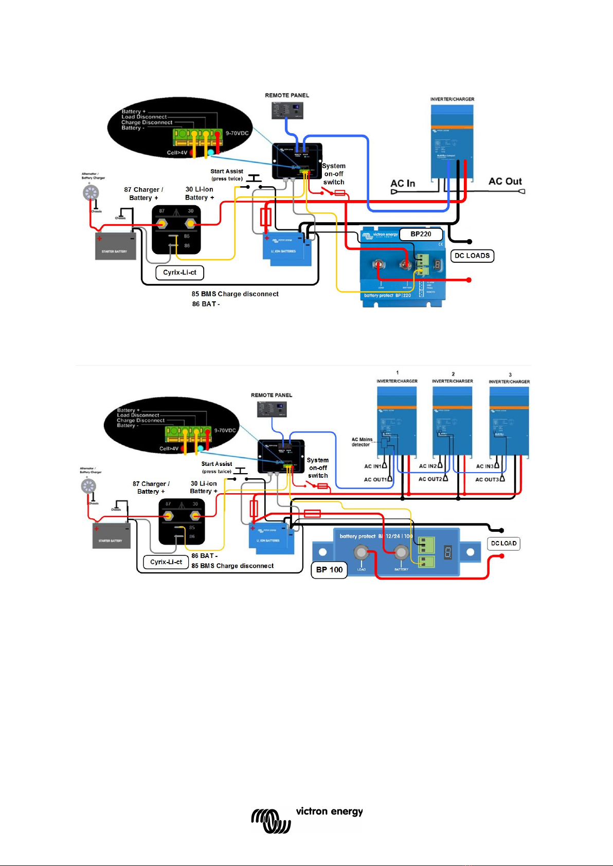
Communicates with all VE.Bus products
The VE.Bus BMS connects to a MultiPlus, Quattro or Phoenix inverter with a standard RJ45 UTP cable.
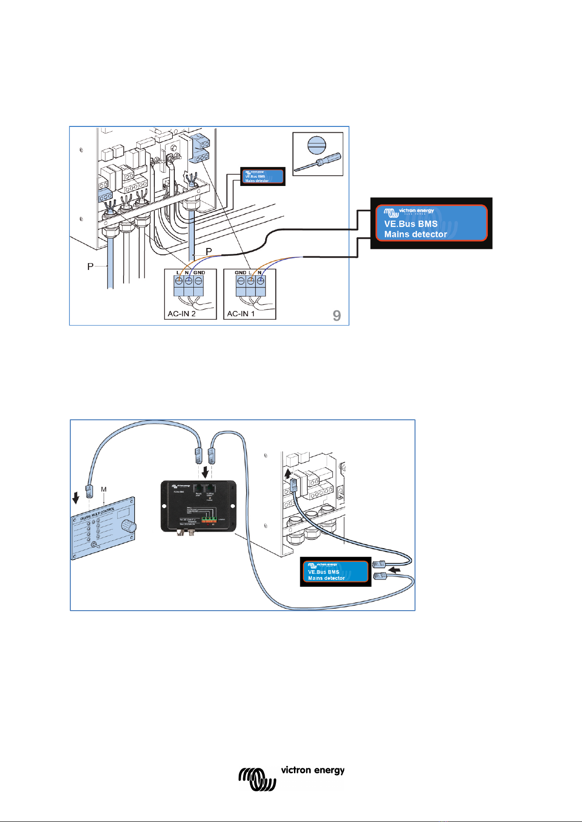
Products without VE.Bus can be controlled as shown below:
Note: AC Detector for MultiPlus and Quattro (included in VE.Bus BMS delivery) not needed for MultiPlus-II models
Load Disconnect
The Load Disconnect output is normally high and becomes free floating in case of imminent cell under voltage. Maximum
current: 2A.
The Load Disconnect output can be used to control
-the remote on/off of a load, and/or
-the remote on/off of an electronic load switch (BatteryProtect, preferred low power consumption solution).
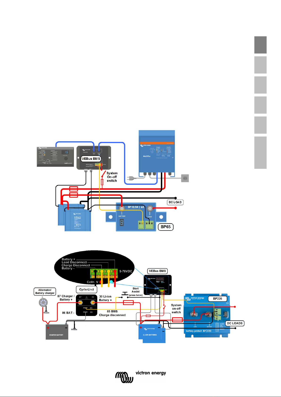
Charge Disconnect
The Charge Disconnect output is normally high and becomes free floating in case of imminent cell over voltage or over
temperature. Maximum current: 10mA.
The Charge Disconnect output can be used to control
-the remote on/off of a charger and/or
-a Cyrix-Li-Charge relay and/or
-a Cyrix-Li-ct Battery Combiner.
LED indicators
-Enabled (blue): VE.Bus products are enabled.
-Cell>4V or temperature (red): charge disconnect output low because of imminent cell over voltage or over
temperature.
-Cell>2,8V (blue): load disconnect output high.
Load disconnect output low when off, due to imminent cell under voltage (Vcell≤2,8V).
2. Safety instructions
Installation must strictly follow the national safety regulations in compliance with the enclosure, installation, creepage, clearance,
casualty, markings and segregation requirements of the end-use application. Installation must be performed by qualified and
trained installers only. Switch off the system and check for hazardous voltages before altering any connection.
• Do not open the Lithium Ion Battery.
• Do not discharge a new Lithium Ion Battery before it has been fully charged first.
• Charge only within the specified limits.
• Do not mount the Lithium Ion Battery upside down.
• Check if the Li-Ion battery has been damaged during transport.
3. Things to consider
3.1 Important warning
Li-ion batteries are expensive and can be damaged due to over discharge or over charge.
Damage due to over discharge can occur if small loads (such as: alarm systems, relays, standby current of certain loads, back
current drain of battery chargers or charge regulators) slowly discharge the battery when the system is not in use.
In case of any doubt about possible residual current draw, isolate the battery by opening the battery switch, pulling the battery
fuse(s) or disconnecting the battery plus when the system is not in use.
A residual discharge current is especially dangerous if the system has been discharged completely and a low cell
voltage shutdown has occurred. After shutdown due to low cell voltage, a capacity reserve of approximately 1Ah per
100Ah battery capacity is left in the battery. The battery will be damaged if the remaining capacity reserve is drawn
from the battery. A residual current of 10mA for example may damage a 200Ah battery if the system is left in
discharged state during more than 8 days.

2
3.2 AC Detector Li-ion software assistant for MultiPlus and Quattro (not needed for MultiPlus-II models)
The AC Detector is a small add-on that can be built in a MultiPlus or Quattro when used together with a LiFePO₄battery and a
VE.Bus BMS. Every VE.Bus BMS is delivered with one AC Detector.
The purpose of the AC Detector is to restart the MultiPlus or Quattro when AC supply becomes available, in case it has been
switched off by the BMS due to low cell voltage.
Without the AC Detector the MultiPlus or Quattro would remain off and therefore would not start recharging the battery after shut
down due to low battery voltage.
The AC detector needs the Li-ion software assistant or the Self-consumption Hub-2 v3 assistant to operate as
intended.
Inverters (DC to AC only) with VE.Bus can be connected directly to the MultiPlus/Quattro input of the BMS, no AC Detector or
assistant needed.
3.3 DC loads with remote on/off terminals
DC loads must be switched off or disconnected in case of imminent cell under voltage.
The Load Disconnect output of the VE.Bus BMS can be used for this purpose.
The Load Disconnect is normally high (equal to battery voltage) and becomes free floating (= open circuit) in case of imminent
cell under voltage (no internal pull down in order to limit residual current consumption in case of low cell voltage).
DC loads with a remote on-off terminal that switches the load on when the terminal is pulled high (to battery plus) and switches it
off when the terminal is left free floating can be controlled directly with the Load Disconnect output.
See appendix for a list of Victron products with this behavior.
For DC loads with a remote on/off terminal that switches the load on when the terminal is pulled low (to battery minus) and
switches it off when the terminal is left free floating, the Inverting remote on-off cable can be used. See appendix.
Note: please check the residual current of the load when in off state. After low cell voltage shutdown a capacity reserve of
approximately 1Ah per 100Ah battery capacity is left in the battery. A residual current of 10mA for example may damage a 200Ah battery
if the system is left in discharged state during more than 8 days.
3.4 DC load: disconnecting the load with a BatteryProtect
A Battery Protect will disconnect the load when:
-input voltage (= battery voltage) has decreased below a preset value, or when
-the remote on/off terminal is pulled low. The VE.Bus BMS can be used to control the remote on/off terminal
Contrary to a Cyrix or contactor, a BatteryProtect can start a load with a large input capacitor such as an inverter or a
DC-DC converter.
3.5 Charging the LiFePO₄battery with a battery charger
Battery charging must be reduced or stopped in case of imminent cell over voltage or over temperature.
The Charge Disconnect output of the VE.Bus BMS can be used for this purpose.
The Charge Disconnect is normally high (equal to battery voltage) and switches to open circuit state in case of imminent cell
over voltage.
Battery chargers with a remote on-off terminal that activates the charger when the terminal is pulled high (to battery plus) and
deactivates when the terminal is left free floating can be controlled directly with the Charge Disconnect output.
See appendix for a list of Victron products with this behavior.
Battery chargers with a remote terminal that activates the charger when the terminal is pulled low (to battery minus) and
deactivates when the terminal is left free floating, the Inverting remote on-off cable can be used. See appendix.
Alternatively, a Cyrix-Li-Charge can be used:
The Cyrix-Li-Charge is a unidirectional combiner that inserts in between a battery charger and the LiFePO₄battery. It will
engage only when charge voltage from a battery charger is present on its charge-side terminal. A control terminal connects to
the Charge Disconnect of the BMS.
3.6 Charging the LiFePO₄battery with an alternator
See figure 6.
The Cyrix-Li-ct is recommended for this application.
The microprocessor controlled Cyrix-Li-ct includes a timer and voltage trend detection. This will prevent frequent switching due
to a system voltage drop when connecting to a discharged battery.

3
EN NL FR DE ES Appendix
4. Installation
4.1 AC Detector for MultiPlus and Quattro (included in VE.Bus BMS delivery). Not needed for MultiPlus-II models.
The purpose of the AC Detector is to restart the MultiPlus or Quattro when AC supply becomes available, in case it has been
switched off by the BMS due to low cell voltage (so that it can recharge the battery).
Note 1: The AC Detector is not needed in case of an inverter.
Note 2: In systems consisting of several units configured for parallel, three phase or split phase operation, The AC Detector should be wired in the
master or leader unit only.
Note 3: The VE.Bus BMS assistant or the Self-consumption Hub-2 v2 assistant must be loaded in all units.
Figure 1: Block diagram with AC Detector in a Quattro
Figure 2: Block diagram with AC Detector in a MultiPlus

4
Installation procedure (see figure 3)
1. Connect the brown and blue input wires to the neutral and phase of the AC-in-1 input.
2. Quattro: connect the brown and blue output wires to the neutral and phase of the AC-in-2 input.
MultiPlus: no AC-in-2 input available. Please cut the AC2 wires close to the AC Detector
Figure 3: Connecting the AC Detector
3. Use the short RJ45 UTP cable to connect the AC Detector to one of the two the VE.Bus sockets in the MultiPlus or
Quattro (see figure 4).
4. Connect the VE.Bus BMS to the AC Detector with a UTP cable (not included).
5. A Digital Multi Control panel must be connected to the VE.Bus BMS. Do not connect a Digital Multi Control panel
directly to a Multi or Quattro (signals from the control panel may be in conflict with signals from the VE.Bus BMS).
6. The ColorControl panel must be connected directly the Multi or Quattro.
Figure 4: VE.Bus connections
4.2 Wire the system: see system examples below
Do not connect to the battery plus at this stage (alternatively: do not insert the battery fuse(s)).
Important:
1. The UTP cable to the inverter or inverter/charger also connects the battery minus to the BMS.
In this case, in order to prevent ground loops, do not wire the battery minus connector of the BMS.
2. Wire the positive supply input of the VE.Bus BMS to the system positive. A system on-off switch in the positive supply
wire will disable the system when opened.

5
EN NL FR DE ES Appendix
4.3 Battery
In case of several batteries in parallel and or series configuration, the two M8 circular connector cord sets of each battery should
be connected in series (daisy chained).
Connect the two remaining cords to the BMS.
4.4. Powering up
In case of a DC only system: connect the battery plus. The system is now ready for use.
In case of a system with Multis, Quattros or inverters with VE.Bus:
4.4.1. After completion of the installation, disconnect the BMS from the VE.Bus and replace by a Victron Interface MK2 and a
computer.
4.4.2. Connect the battery plus.
4.4.2. Configure inverter/charger(s) or inverter(s) for parallel or three phase configuration if applicable.
Inverter/chargers: the AC Detector should be installed only in the master or leader of a parallel or three phase system.
Inverters: AC detector not needed.
4.4.3. Load the VE.Bus BMS assistant or a Hub assistant in all units (must be done for each unit separately)
4.4.4. Remove the MK2 and reconnect to the BMS.
4.4.5. The system is now ready for use
5. System examples
Figure 5: System with MultiPlus and DC loads
Note: the BMS is connected to the battery minus by the UTP cable between the BMS and the inverter/charger.
Therefore, in order to prevent ground loops, do not wire the BMS minus connector.
Figure 6: DC only system for a boat or vehicle with parallel connection of the starter- and Li-ion battery
Note: in this case the battery minus of the BMS must be wired.

6
Figure 7: System for a boat or vehicle with inverter/charger
Note: the BMS is connected to the battery minus by the UTP cable between the BMS and the inverter/charger.
Therefore, in order to prevent ground loops, do not wire the BMS minus connector.
Figure 8: System example for a boat or vehicle with a three phase inverter/charger configuration (DC fuses not shown, except
for the the Li-ion battery fuse)
Note 1: the AC Detector is installed in the leader only.
Note 2: the BMS is connected to the battery minus by the UTP cable between the BMS and the inverter/charger.
Therefore, in order to prevent ground loops, do not wire the BMS minus connector.

7
EN NL FR DE ES Appendix
Figure 9: System example for a boat or vehicle with a 24V Li-ion system, a 24V alternator and a 12V starter battery.
To charge the starter battery: use a DC-DC converter or a small battery charger connected to the Multi or Quattro.
Alternators which need DC voltage on the B+ output to start charging can be started by pushing the Start Assist push button
once the engine is running.
Note: the BMS is connected to the battery minus by the UTP cable between the BMS and the inverter/charger.
Therefore, in order to prevent ground loops, do not wire the BMS minus connector.
Figure 10: Solar application with an MPPT with VE.Direct port and a Phoenix Inverter 24/1200.

8
Figure 11: Solar application with two MPPT 150/85
The MPPT 150/85 (and the latest model MPPT 150/70) has a remote on-off port which can be controlled directly by the VE.Bus
BMS
Note: the BMS is connected to the battery minus by the UTP cable between the BMS and the inverter/charger.
Therefore, in order to prevent ground loops, do not wire the BMS minus connector.
6. Dimensions

9
EN NL FR DE ES Appendix
7. Frequently asked questions
Q1: I have disconnected the VE.Bus BMS, and now my Multi or Quattro will not switch on, why?
A Multi or Quattro programmed with the VE.Bus BMS assistant, and unable to find a VE.Bus BMS on the bus, will go into an
emergency mode. In this mode it will charge the batteries with 5 Ampère max, up to 12V, 24V or 48V, depending on system
voltage. Note that in this mode, the only LED which is on is the Mains On LED. If you disconnect the AC input from the
Multi/Quattro, it will switch off. It will not start to invert since it cannot get verification on the battery health from the VE.Bus BMS.
Note that, when the batteries are depleted or disconnected, Quattros need to be powered from AC input 1. Supplying power to
AC Input 2 will not make a Quattro switch on and start charging.
Q2: The batteries are empty and the Multi/Quattro will not start to charge, how to get the system up and running again.
When lithium batteries are depleted (the voltage is around 9V or even lower) the battery voltage might be below the operating
window of the VE.Bus BMS. In that case the VE.Bus BMS will not be able to start the Multi/Quattro, even if an AC Detector is
installed. To start the system again, disconnect the VE.Bus BMS from the Multi, and refer to Q1. Note that it might be necessary
to disconnect any Blue Power Panels, NMEA2000 interfaces or other similar smart products. As long as they are not switched
on themselves, they can prevent the Multi/Quattro from starting up.
A simpler option to revive a depleted system might be to connect a small battery charger, for example 5 Ampère, and wait for
the battery voltage to get back up to 12 Volt.
Q3: What happens with the Multi/Quattro when the BMS gives a low cell voltage signal?
The Multi/Quattro will be in charger only mode: when AC input is present, it will charge the batteries. And when the AC input is
not present, it will switch off.
Q4: What happens with the Multi/Quattro when the BMS gives a high cell voltage signal?
The high cell voltage signal will only be given when there are unbalanced cells. The Multi/Quattro will switch to bulk, and starts
charging with a reduced charge current. This allows the balancing system to rebalance the cells.

10
8. Specifications
Cyrix Li-ion ct
(see Cyrix Li-ion datasheet for more
information)
12/24-120 24/48-120
Continuous current
120A
Connect voltage
From 13,7V to 13,9V and 27,4V to 27,8V
with intelligent trend detection
Disconnect voltage
From 13,2V to 13,4V and 26,4V to 26,8V
with intelligent trend detection
Start Assist
Yes
(The Cyrix remains engaged during 15
seconds after the control input has been
pulled twice to battery minus.)
Cyrix Li-ion load 12/24-120 24/48-120 24/48-120
Please use a Battery Protect instead: much lower power consumption
Cyrix Li-ion Charge 12/24-120 24/48-120
Continuous current
120A
120A
Connect voltage
Engages when voltage on the charger side
exceeds 13,7V to 13,9V and 27,4V to 27,8V
with intelligent trend detection
Engages when voltage on the charger side
exceeds 27,4V to 27,8V and 54,8V to 55,6V with
intelligent trend detection
Disconnect voltage From 13,2V to 13,4V and 26,4V to 26,8V
with intelligent trend detection
From 26,4V to 26,8V and 52,8V to 53,6V
with intelligent trend detection
Charge not active detection The Cyrix disengages every hour and remains open in case of low voltage on the charger side
General 12/24-120 24/48-120
Over voltage disconnect
16V / 32V
32V / 64V
Over temperature disconnect
Yes
Current consumption when open
<4mA
Current consumption when closed
<220mA / < 110mA
< 110mA / <60mA
Operating temperature range
-20 to +50°C
Protection category
IP54
Weight kg (lbs)
0,11 (0.24)
Dimensions h x w x d in mm
(h x w x d in inches)
46 x 46 x 80
(1.8 x 1.8 x 3.2)
VE.Bus BMS
Input voltage range 9 – 70VDC
Current draw, normal operation 10mA (excluding Load Disconnect current)
Current draw, low cell voltage 2mA
Load Disconnect output
Normally high (output voltage ≈ supply voltage – 1V)
Floating when load needs to be disconnected
Source current limit: 2A
Sink current: 0A
Charge Disconnect output
Normally high, (output voltage ≈ supply voltage – 1V)
Floating when charger should be disconnected
Source current limit: 10mA
Sink current: 0A
GENERAL
VE.Bus communication port Two RJ45 sockets to connect to all VE.Bus products
Operating temperature -20 to +50°C 0 - 120°F
Humidity Max. 95% (non-condensing)
Protection grade
IP20
ENCLOSURE
Material and colour ABS, matt black
Weight kg 0,1
Dimensions (hxwxd) in mm 105 x 78 x 32
STANDARDS
Standards: Safety
Emission
Immunity
Automotive Directive
EN 60950
EN 61000-6-3, EN 55014-1
EN 61000-6-2, EN 61000-6-1, EN 55014-2
EN 50498

11
EN NL FR DE ES Appendix
EN
Appendix:
Loads which can be controlled directly
by the Load Disconnect output of the BMS
Inverters:
All Phoenix inverters VE.Direct 250/375/500/800/1200
Phoenix 12/800 Phoenix 24/800
Phoenix 12/1200 Phoenix 24/1200
Phoenix 48/800 Phoenix 48/1200
DC-DC converters:
All Tr type DC-DC converters
Orion 12/24-20
Orion 24/12-25
Orion 24/12-40
Orion 24/12-70
Loads for which a Inverting remote on-off cable
is needed
(article number ASS030550100)
Inverters:
Phoenix 12/180
Phoenix 24/180
Phoenix 12/350
Phoenix 24/350
All Phoenix inverters rated at 3kVA and more
Load disconnect switch for which a
Non inverting remote on-off cable
is needed
(article number ASS030550200)
BatteryProtect BP-40i
BatteryProtect BP-60i
BatteryProtect BP-200i
(Non inverting remote on-off cable is
not needed for the more recent models
BP-50, BP-60, BP-100, BP-220 and BP 48V-100A)
For Skylla TG battery chargers a
Non inverting remote on-off cable
Is needed
(article number ASS030550200)
For Skylla-i battery chargers a
Skylla-i remote on-off cable
Is needed
(article number ASS030550400)


1
EN NL FR DE ES Appendix
1. Algemene beschrijving
Beschermt elke afzonderlijke cel van een Victron lithium-ijzerfosfaat- (LiFePO₄) accu
Elke afzonderlijke cel van een LiFePO₄-accu moet worden beschermd tegen overspanning, onderspanning en overtemperatuur.
Victron LiFePO₄-accu's beschikken over een geïntegreerde celbalanceer-, temperatuur- en spanningsregeling (in het Engels
Balancing, Temperature and Voltage control, kort BTV, genoemd). Deze wordt met twee ronde M8-aansluitkabelssets op het
VE.Bus BMS aangesloten.
De BTV van meerdere accu's kan in een ringnetwerk met elkaar worden verbonden. Zie voor meer informatie de documentatie
van onze LiFePO4-accu.
Taken van het BMS:
-het uitschakelen of ontkoppelen van belastingen in geval van dreigende onderspanning van de cellen,
-het verlagen van de laadstroom in geval van dreigende overspanning of overtemperatuur van de cellen (zie voor
VE.Bus-producten de onderstaande informatie), en
-het uitschakelen of ontkoppelen van de acculaders in geval van dreigende overspanning of overtemperatuur van de
cellen.
Beschermt 12V-, 24V- en 48V-systemen
Bedrijfsspanningsbereik van het BMS: 9 tot 70V DC.
Communiceert met alle VE.Bus-producten
Het VE.Bus BMS kan met een standaard RJ45 UTP-kabel worden aangesloten op een MultiPlus-, Quattro- of Phoenix-
omvormer.
Producten zonder VE.Bus kunnen zoals onderstaand weergegeven worden geregeld:
Opmerking: AC Detector voor MultiPlus en Quattro (inbegrepen bij VE.Bus BMS levering) niet nodig voor de MultiPlus-
II modellen
Load Disconnect (belasting onderbreken)
De uitgang Load Disconnect staat normaal gesproken op HIGH (hoog) en wordt ‘free floating’ (vrij zwevend) in geval van
dreigende onderspanning van de cellen. Maximale stroom: 2A.
De uitgang Load Disconnect kan worden gebruikt om de volgende functies te regelen:
-het op afstand in- of uitschakelen van een belasting en/of
-het op afstand in- of uitschakelen van een elektronische belastingsschakelaar (BatteryProtect, voorkeur oplossing
voor een laag stroomverbruik).
Charge Disconnect (laden onderbreken)
De uitgang Charge Disconnect staat normaal gesproken op HIGH en wordt ‘free floating’ in geval van dreigende overspanning
of overtemperatuur van de cellen. Maximale stroom: 10mA.
De uitgang Charge Disconnect kan worden gebruikt om de volgende functies te regelen:
-het op afstand in- of uitschakelen van een acculader en/of
-een Cyrix-Li-Charge-relais en/of
-een Cyrix-Li-ct Battery Combiner.
LED-lampjes
-Brandt (blauw): VE.Bus-producten zijn ingeschakeld.
-Cel>4V of temperatuur (rood): de uitgang Charge Disconnect staat op LOW (laag) door dreigende overspanning of
overtemperatuur van de cellen.
-Cel>2,8V (blauw): de uitgang Load Disconnect staat op HIGH (hoog).
De uitgang Load Disconnect staat op LOW als deze door dreigende onderspanning van de cellen (Vcel≤2,8V) is
uitgeschakeld.
2. Veiligheidsaanwijzingen
De installatie moet precies worden uitgevoerd volgens de nationale veiligheidsvoorschriften en in overeenstemming met de voor
eindgebruik gestelde eisen betreffende behuizing, installatie, lekstroom, speling, verliezen, markeringen en segregatie. De
installatie mag enkel worden uitgevoerd door gekwalificeerde en geschoolde installatiemonteurs. Schakel het systeem uit en
controleer het op gevaarlijke spanningen voordat u wijzigingen aan de aansluitingen aanbrengt.
• Open de lithium-ionaccu niet.
• Ontlaad een nieuwe lithium-ionaccu niet voordat deze eerst volledig is opgeladen.
• Laad de accu enkel op binnen de aangegeven grenswaarden.
• Monteer de lithium-ionaccu niet ondersteboven.
• Controleer of de lithium-ionaccu tijdens het transport beschadigd is geraakt.

2
3. Neem het volgende in acht
3.1 Belangrijke aanwijzing
Lithium-ionaccu's zijn duur en kunnen beschadigd raken door te diepe ontlading of overlading.
Beschadiging als gevolg van te diepe ontlading kan optreden als lage belastingen (zoals: alarmsystemen, relais, stand-by-
stroom van bepaalde belastingen, retourstroomverbruik van acculaders of ladingsregelaars) langzaam de accu ontladen als het
systeem niet in gebruik is.
Koppel in geval van twijfel over een mogelijke reststroomstoot de accu los door de accuschakelaar te openen, de
accuzekering(en) te verwijderen of de pluspool van de accu los te koppelen als het systeem niet in gebruik is.
Een restontladingsstroom is vooral gevaarlijk als het systeem volledig is ontladen en door te lage celspanning is
uitgeschakeld. Na een uitschakeling door een te lage celspanning resteert een reservecapaciteit van ongeveer 1Ah per
100Ah accucapaciteit in de accu. De accu zal beschadigd raken als de resterende reservecapaciteit aan de accu wordt
onttrokken. Een reststroom van 10mA kan bijvoorbeeld een 200Ah-accu beschadigen als het systeem gedurende meer
dan 8 dagen in ontladen toestand blijft.
3.2 De lithium-ion-software-assistent ‘AC Detector’ voor MultiPlus en Quattro (niet nodig voor de MultiPlus-II modellen)
De AC Detector (wisselstroomdetector) is een kleine uitbreiding die kan worden ingebouwd in een Multiplus of Quattro als deze
samen met een LiFePO₄-accu en een VE.Bus BMS worden gebruikt. De VE.Bus BMS wordt standaard geleverd met
AC Detector.
De taak van de AC Detector is om de Multiplus of Quattro opnieuw te starten als weer wisselstroom beschikbaar is nadat het
apparaat door het BMS als gevolg van een te lage celspanning is uitgeschakeld.
Zonder de AC Detector zouden de Multiplus of Quattro uitgeschakeld blijven en daardoor zou de accu na uitschakeling door een
te lage accuspanning niet weer beginnen met opladen.
De AC Detector is hiervoor afhankelijk van de lithium-ion-software-assistent of de Eigen verbruik Hub-2 v3 assistent.
Omvormers (alleen DC naar AC) met VE.Bus kunnen direct worden aangesloten op de MultiPlus/Quattro-ingang van het BMS.
Hiervoor is geen AC Detector of assistent nodig.
3.3 DC-belastingen met aansluitingen voor in- of uitschakelen op afstand
DC-belastingen moeten worden uitgeschakeld of ontkoppeld in geval van dreigende onderspanning van de cellen.
Voor dit doel kan de uitgang Load Disconnect van het VE.Bus BMS worden gebruikt.
De uitgang Load Disconnect staat normaal gesproken op HIGH (net als de accuspanning) en wordt ‘free floating’ (= open
circuit) in geval van dreigende onderspanning van de cellen (geen interne ‘pull down’ om het resterend stroomverbruik in geval
van een lage celspanning te beperken).
DC-belastingen met een aansluiting voor in- of uitschakelen op afstand die de belasting inschakelen als de aansluiting op HIGH
wordt gezet (op de plus van de accu) en deze uitschakelen als de aansluiting op ‘free floating’ wordt gezet, kunnen direct met
de uitgang Load Disconnect worden geregeld.
In de bijlage vindt u een lijst met Victron-producten die over deze eigenschap beschikken.
Voor DC-belastingen met een aansluiting voor in- of uitschakelen op afstand die de belasting inschakelen als de aansluiting op
LOW gezet (naar de min van de accu) en deze uitschakelen als de aansluiting op ‘free floating’ wordt gezet, kan de
omvormkabel voor het op afstand in- of uitschakelen worden gebruikt. Zie bijlage.
Opmerking: controleer de reststroom van de belasting als deze is uitgeschakeld. Na een uitschakeling door een te lage celspanning
resteert een reservecapaciteit van ongeveer 1Ah per 100Ah accucapaciteit in de accu. Een reststroom van 10mA kan bijvoorbeeld een
200Ah-accu beschadigen als het systeem gedurende meer dan 8 dagen in ontladen toestand blijft.
3.4 DC-belasting: ontkoppeling van de belasting met een BatteryProtect (alleen beschikbaar voor 12V en 24V)
Een Battery Protect ontkoppelt de belasting in de volgende gevallen:
-als de ingangsspanning (= accuspanning) onder de vooringestelde waarde is gedaald, of
-als de aansluiting voor het op afstand in- of uitschakelen op LOW is gezet. Het VE.Bus BMS kan worden gebruikt om
de aansluiting voor het op afstand in- of uitschakelen te regelen:
(Dan is een niet-omvormende kabel voor het op afstand in- of uitschakelen nodig).
In tegenstelling tot een Cyrix-relais of een schakelaar kan een BatteryProtect een belasting met een grote
ingangscondensator starten, zoals een omvormer of een DC-DC-omvormer.
3.5 Opladen van LiFePO₄-accu's met een acculader
Het opladen van de accu moet worden verminderd of gestopt in geval van dreigende overspanning of overtemperatuur van de
cellen.
Voor dit doel kan de uitgang Charge Disconnect van het VE.Bus BMS worden gebruikt.
De uitgang Charge Disconnect staat normaal gesproken op HIGH (net als de accuspanning) en schakelt in geval van dreigende
overspanning van de cellen over op de toestand ‘open-circuit’.
Acculaders met een aansluiting voor het op afstand in- of uitschakelen die de acculader activeren als de aansluiting op HIGH
wordt gezet (op de plus van de accu) en deze deactiveren als de aansluiting op ‘free floating’ wordt gezet, kunnen direct met de
uitgang Charge Disconnect worden geregeld.
In de bijlage vindt u een lijst met Victron-producten die over deze eigenschap beschikken.
Voor acculaders met een aansluiting voor het op afstand in- of uitschakelen die de acculader inschakelt als de aansluiting op
LOW wordt gezet (op de min van de accu) en deze uitschakelt als de aansluiting op ‘free floating’ wordt gezet, kan de
omvormende kabel voor het op afstand in- of uitschakelen worden gebruikt. Zie bijlage.

3
EN NL FR DE ES Appendix
Als alternatief kan een Cyrix-Li-Charge worden gebruikt:
De Cyrix-Li-Charge is een éénrichtingskoppelaar die tussen een acculader en de LiFePO₄-accu wordt geschakeld. Deze wordt
alleen actief als de laadspanning van de acculader beschikbaar is op de aansluiting aan de oplaadzijde. Een regelklem wordt
met de aansluiting Charge Disconnect van het BMS verbonden.
3.6 Opladen van LiFePO₄-accu's met een wisselstroomgenerator
Zie afbeelding 6.
Voor deze toepassing wordt de Cyrix-Li-ct aanbevolen.
De door een microprocessor bestuurde Cyrix-Li-ct beschikt over een timer- en spanningstrenddetectie. Dit voorkomt
herhaaldelijk omschakelen door een systeemspanningsdaling bij aansluiting van een ontladen accu.

4
4. Installatie
4.1 AC Detector voor MultiPlus en Quattro (inbegrepen in de levering van een VE.Bus BMS). Niet nodig voor de
MultiPlus-II modellen.
De taak van de AC Detector is het om de Multiplus of Quattro opnieuw te starten als wisselstroom beschikbaar is in geval deze
is uitgeschakeld door het BMS als gevolg van een te lage celspanning (zodat de accu weer kan worden opgeladen).
Opmerking 1: De AC Detector is in geval van een omvormer niet nodig.
Opmerking 2: In systemen die bestaan uit meerdere apparaten, die geconfigureerd zijn voor parallelle, driefasen- of gesplitste fase-werking, dient
de AC Detector enkel met het master- of leidende apparaat te zijn verbonden.
Opmerking 3: De VE.Bus BMS assistent of de Eigen verbruik Hub-2 v2 assistent moet op alle apparaten worden geladen.
Afbeelding 1: Blokschema met AC Detector in een Quattro
Afbeelding 2: Blokschema met AC Detector in een MultiPlus

5
EN NL FR DE ES Appendix
Installatieprocedure (zie afbeelding 3)
1. Verbind de bruine en blauwe ingangsdraden met de nulleider en de fase van de AC-in-1 ingang.
2. Quattro: Verbind de bruine en blauwe uitgangsdraden met de nulleider en de fase van de AC-in-2 ingang.
MultiPlus: geen AC-in-2-ingang beschikbaar. Knip de AC2-draden dicht bij de AC Detector af.
Afbeelding 3: Aansluiting van de AC Detector
3. Gebruik de korte RJ45 UTP-kabel om de AC Detector met één van de twee VE.Bus-bussen in de Multiplus of Quattro
te verbinden (zie afbeelding 4).
4. Verbind het VE.Bus BMS met de AC Detector via een UTP-kabel (niet meegeleverd).
5. Een Digital Multi Control pandeel moet met het VE.Bus BMS worden verbonden. Verbind een Digital Multi Contro,
paneel niet direct met een Multi of Quattro (tussen de signalen van het controlepaneel en de signalen van het VE.Bus
BMS kan een conflict ontstaan).
6. Het Color Control paneel moet direct worden verbonden met de Multi of Quattro.
Afbeelding 4: VE.Bus-aansluitingen
4.2 Bedrading van het systeem: zie onderstaande systeemvoorbeelden
Nu nog niet met de plus van de accu verbinden (of nog niet de zekering(en) van de accu plaatsen).
Belangrijke aanwijzing:
1. De UTP-kabel naar de omvormer of omvormer/lader verbindt ook de minpool van de accu met het BMS.
Bedraad in dat geval om aardingsfoutlussen te voorkomen niet de stekker voor de minpoolaansluiting van de accu
van het BMS.
2. Verbind de pluspool van de voedingsingang met het VE.Bus BMS met de pluspool van het systeem. Een aan/uit-
schakelaar van het systeem in de plus-voedingsdraad schakelt het systeem uit als deze wordt geopend.

6
4.3. Accu
In geval van meerdere parallel of in serie geschakelde accu's, dienen de twee ronde M8-aansluitstekkersets van elke accu in
serie (in een ringnetwerk) te worden aangesloten.
Verbind de twee overige stekkersets met het BMS.
4.4. Inschakelen
In geval van een systeem dat enkel voor gelijkstroom geschikt is: verbind de pluspool van de accu. Het systeem is nu klaar voor
gebruik.
In geval van een systeem met Multi's, Quattro's of omvormers met VE.Bus:
4.4.1. Koppel na voltooiing van de installatie het BMS los van de VE.Bus en vervang deze door een Victron Interface MK2 en
een computer.
4.4.2. Verbind de pluspool van de accu.
4.4.2. Configureer, indien van toepassing, de omvormer(s)/lader(s) of omvormer(s) voor een parallelle of driefase-configuratie.
Omvormers/laders: de AC Detector dient enkel in het master- of leidende apparaat van een parallel of driefasesysteem te
worden geïnstalleerd. Omvormers: er is geen AC Detector nodig.
4.4.3. Laad de BMS VE.Bus-assistent of een Hub-assistent op alle apparaten (moet voor elk apparaat afzonderlijk worden
uitgevoerd).
4.4.4. Verwijder de MK2 en sluit het BMS weer aan.
4.4.5. Het systeem is nu klaar voor gebruik.
5. Systeemvoorbeelden
Afbeelding 5: Systeem met MultiPlus en DC-belastingen
Opmerking: het BMS wordt verbonden met de minpool van de accu via de UTP-kabel tussen het BMS en de omvormer/lader.
Om aardingsfoutlussen te voorkomen, mag daarom de min-stekker van het BMS niet worden aangesloten.
Afbeelding 6: DC-systeem voor een boot of voertuig met parallelle aansluiting van de start- en lithium-ion-accu
Opmerking: in dat geval moet de minpool van de accu van het BMS worden aangesloten.
Table of contents
Languages: