Video Clarity RTM-1RU User manual

Real-Time Monitor (RTM)
System Guide
Copyright © 2009-2018 Video Clarity, Inc.

01/29/2019 Rev.3.0 2 of 40
TABLE OF CONTENTS
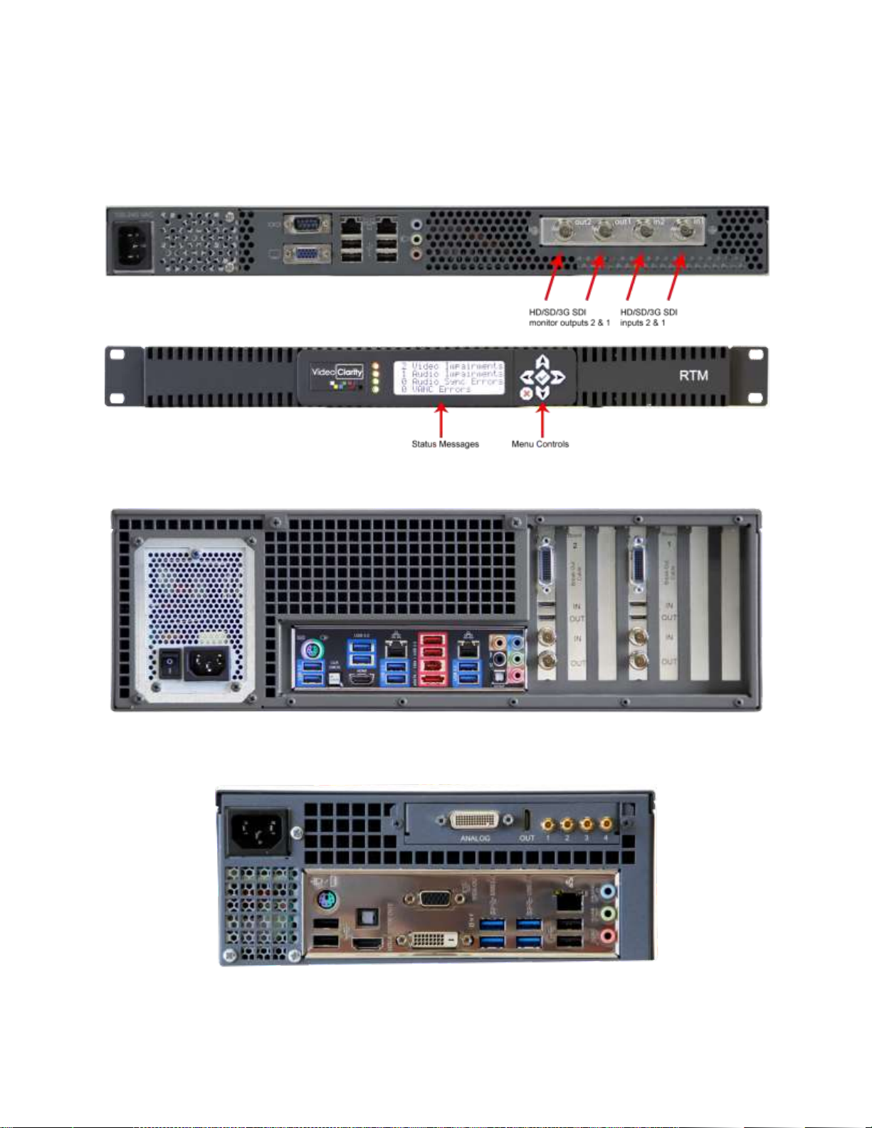
1REAL TIME MONITORING (RTM) SYSTEM 4
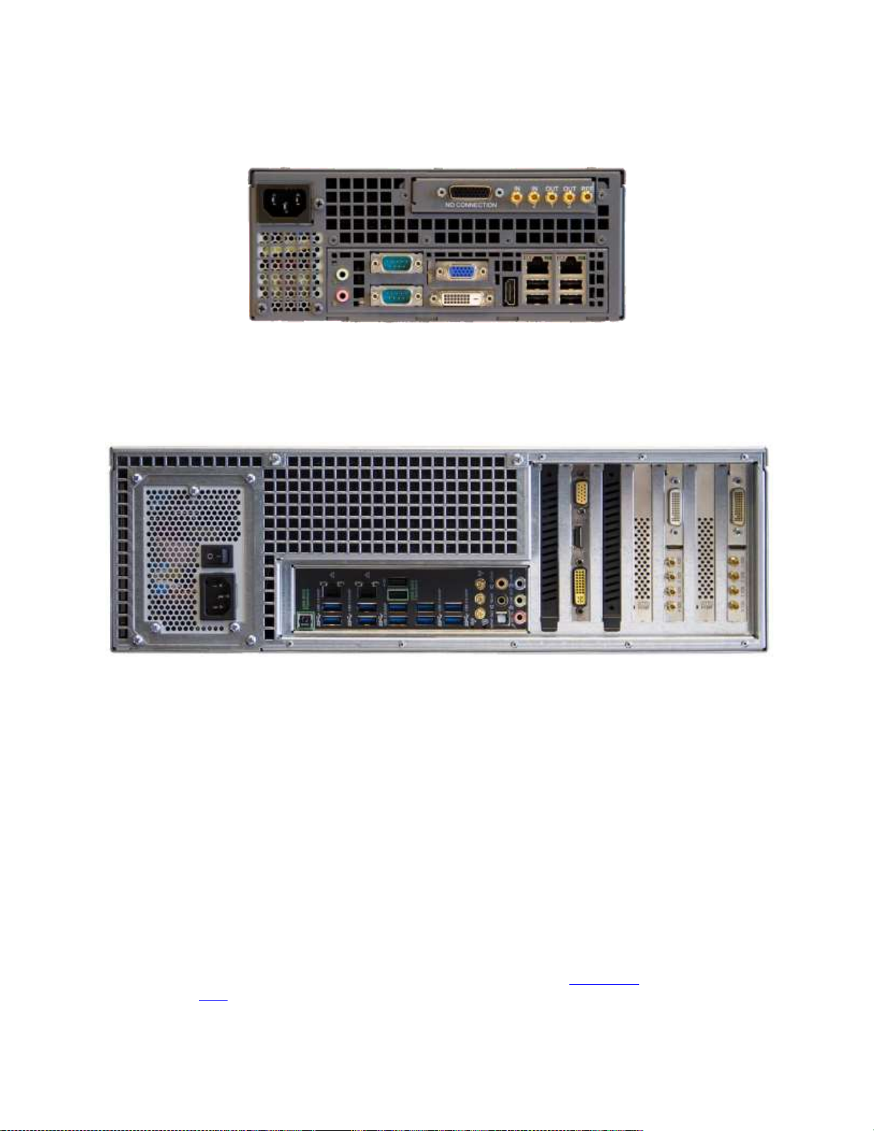
2HARDWARE QUICK SETUP GUIDE 5
3SOFTWARE QUICK SETUP GUIDE 7
4TYPICAL APPLICATIONS 10
4.1 LONG DURATION TESTING............................................................................................................10
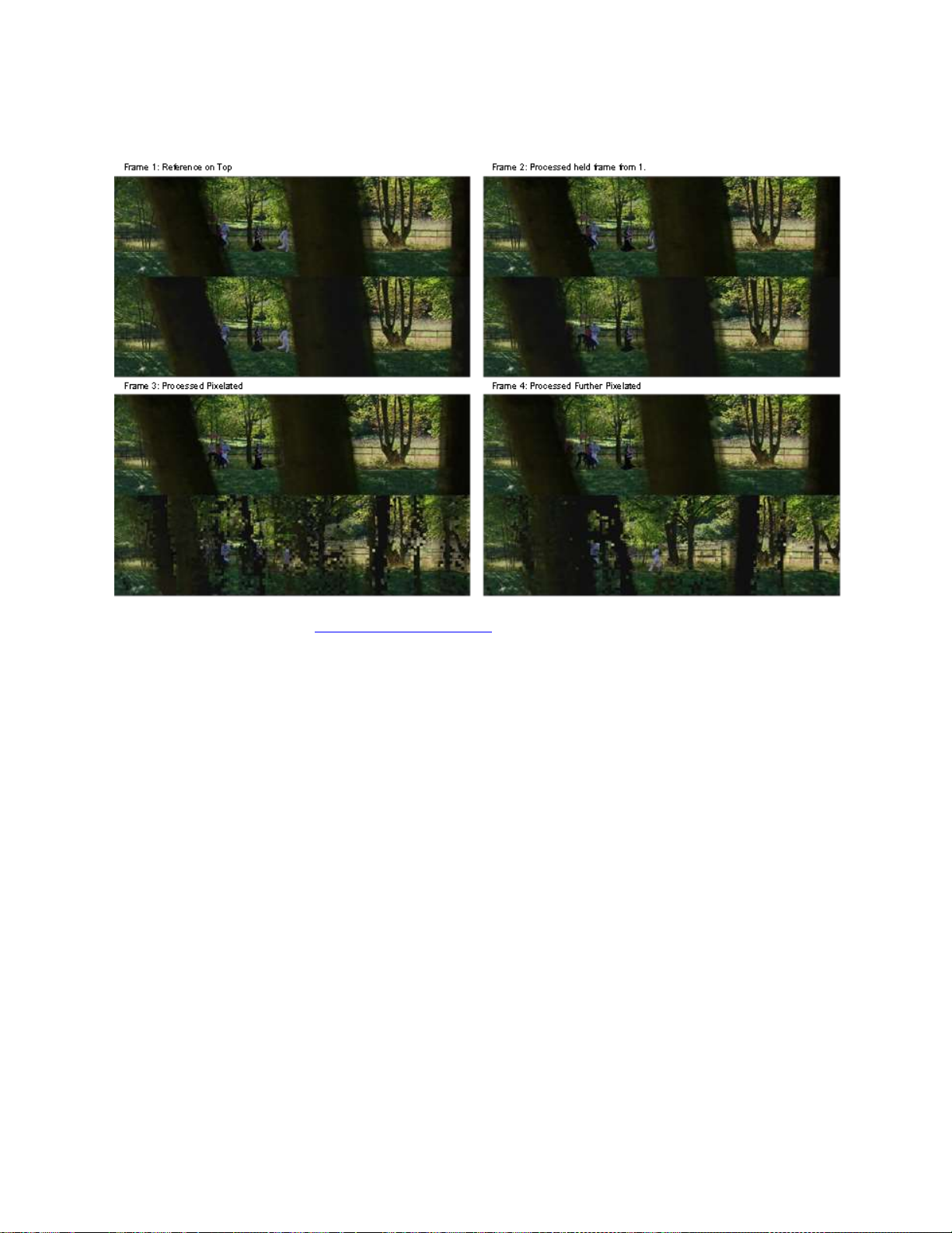
4.2 BROADCAST MONITORING ............................................................................................................10
4.2.1Reference Content Caused the Error....................................................................................10
4.2.2 Processing Content Caused the Error ..................................................................................11
5SETTING RTM PARAMETERS 12
5.1 RTM STATUS ..............................................................................................................................12
5.2 RTM CONTROLS..........................................................................................................................12
5.3 RTM ALIGNMENT.........................................................................................................................13
5.4 RTM VIDEO QUALITY...................................................................................................................13
5.5 RTM AUDIO QUALITY...................................................................................................................14
6SETTING NORMAL CONFIGURATION PARAMETERS 15
6.1 INPUTS PANE...............................................................................................................................15
6.1 IP/COMPRESSED CONFIGURATION PANE.......................................................................................16
6.1.1 Settings..................................................................................................................................16
6.2 LEGACY IP/COMPRESSED CONFIGURATION PANE..........................................................................17
6.3 ALIGNMENT PANE ........................................................................................................................19
6.4 DYNAMIC REALIGNMENT PANE......................................................................................................21
6.5 VIDEO METRIC PANE....................................................................................................................23
6.6 AUDIO METRIC PANE....................................................................................................................25
6.7 VANC METRIC PANE ...................................................................................................................26
6.8 SEQUENCE CREATION PANE.........................................................................................................27
6.9 LOGS AND ALERTS PANE..............................................................................................................29
7LOG FILES 30
7.1 AUDIOALIGN.LOG.........................................................................................................................30
7.2 AUDIOAVG.LOG............................................................................................................................30
7.3 RTMLOG.LOG..............................................................................................................................31
7.4 SESSION.LOG...............................................................................................................................31
7.5 PSNRAVG.LOG/DMOSAVD.LOG......................................................................................................31
7.6 PSNR/.DMOS AND .AUDIO FILES.....................................................................................................32
8RTM LOG GRAPHER 33
8.1 THE APPLICATION........................................................................................................................33
8.2 INTERACTION WITH THE GUI.........................................................................................................33
9COMMAND-LINE INTERFACE 34
9.1 RTMSERVER.EXE........................................................................................................................34
9.2 RTM.EXE......................................................................................................................................34
9.3 COMMANDS DETAILED..................................................................................................................35
Preview...............................................................................................................................................35
RestoreConfig.....................................................................................................................................35
SaveConfig.........................................................................................................................................36
Stop ....................................................................................................................................................36
NewFolder ..........................................................................................................................................36
VideoMetric.........................................................................................................................................36

01/29/2019 Rev.3.0 3 of 40
VideoLogAveraging(AudioLogAveraging)..........................................................................................36
MetricWindow.....................................................................................................................................37
BorderValue........................................................................................................................................37
AudioMetric.........................................................................................................................................37
ConfigLipSync ....................................................................................................................................37
ConfigLKFS........................................................................................................................................37
ConfigSpatialRange............................................................................................................................37
ConfigFullAlignment ...........................................................................................................................38
ConfigDynamicAlign...........................................................................................................................38
GetAlignmentFailCode .......................................................................................................................38
SetInput ..............................................................................................................................................38
ConfigScaling .....................................................................................................................................38
ConfigInputIP......................................................................................................................................39
ConfigInputFile ...................................................................................................................................39
ConfigStreamScaling..........................................................................................................................39
ApplyStreamChanges ........................................................................................................................39
SequenceConfig.................................................................................................................................39
ConfigLogFile .....................................................................................................................................40
GetRTMErrorCode .............................................................................................................................40
ConfigVANC.......................................................................................................................................40
ConfigRateConvert.............................................................................................................................40
ConfigStreamModule..........................................................................................................................40

01/29/2019 Rev.3.0 4 of 40
1 Real Time Monitoring (RTM) System
At the processing layer, problems arise when down-converting HD to SD, changing formats, and
compressing the signal into the available bandwidth. Also the separate processing of audio, video, and
data can lead to synchronization problems.
At the transmitting layer, broadcasters encounter their familiar RF problems with a new challenge -
coverage and interference problems caused by more channels at lower powers. Broadcasters rely on
telecommunication technology so latency, packet loss, and synchronization add additional concerns.
Errors in one layer can cause errors in the next. For example blockiness caused by compression looks
similar to packet loss/bit errors.
For this reason, the quality must be monitored at multiple points across the network including at the end
users device (set-top box, mobile).
RTM - a full reference broadcast quality monitor:
- Measures the audio and video quality
- Measures the audio and video delay (lip-sync)
- Measures the audio program loudness of both source (1) and test (2) input
- Measures the VANC data lines integrity
- Alarms and records the A/V sequences if any of the above have fallen below the degradation threshold
as set by the user
The degradation threshold is pre-configured by your engineering team and set to detect:
- Fine detail - blur, blockiness, and
- Gross impairment - loss of signal, picture freezes, lip-sync.
RTM can compare any combination of
- SDI input
- IP input
- File input
Applications
- In-service broadcast monitoring
- Long duration QA testing for networks or devices
-Television Production Truck to Central Office lip-sync and quality pre-check
RTM includes reference test patterns, which can be exported as QuickTime, RAW, or AVI files or played
through SDI outputs. These can be stored in your Production Truck to check lip-sync and A/V quality or
can be used for QA testing.
Being a full-reference monitoring device, RTM is not influenced by the “artistic” quality of the source.
RTM continually aligns to measure lip-sync and it reports any frame loss.

01/29/2019 Rev.3.0 5 of 40
2 Hardware Quick Setup Guide
Figure 1: RTM-1RU Back Panel
Models: RTM-S1081
RTM-S1082
Figure 2: RTM-1RU Front Controls
Figure 3: RTM-3G Back Panel
Models: RTM-S3082 (discontinued model)
RTM-S3083 (discontinued model)
Figure 4: RTM 3G Portable Back Panel (supplied with SMB to BNC, mini HDMI and also supplied
with analog breakout cables for playback)
Model: RTM-S2043
This unit has its HDSDI connector labels 1,2,3,4.
Inputs are connections 1 and 2. Outputs are connections 3 and 4.

01/29/2019 Rev.3.0 6 of 40
Figure 5: RTM HD 2U Portable Back Panel (supplied with 5 SMB to BNC conversion cables)
Model: RTM-S2042
Figure 6: RTM 4K Back Panel (Supplied with two sets of Quad SMB to BNC conversion cables for
inputs 1 and 2 and mini HDMI cables for error recording playback from either or both outputs)
Models: RTM-S8084 (10 TB storage model) or RTM-8084-5 (5 TB storage model)
RTM 4K Important Notes:
4K monitoring and measurement test operation is for 3840x2160p resolution input via Quad HDSDI on
Input 1 to be compared to same frame rate and resolution on Quad HDSDI Input 2. Frame rates of
3840X2160p video supported on both inputs are 60, 59.94, 50, 30, 29.97, 25, 24, or 23.98Hz. Other
modes of operation such as IP stream decoding or file-based operation at the 4K resolution and frame
rates are not supported.
To operate RTM (regardless of model):
- Connect the included USB Keyboard and Mouse
- Connect a HDMI, DVI or VGA monitor to the system graphics output connector
- Connect signals to Input 1 and Input 2 (For file-based operation, this is not necessary)
- Connect signals for Input 1 and 2 via IP GNIC (applied up to HD or lower resolutions only) can
selected for MPEG stream decoding on Input tab in Configuration menu with same NIC or
separate NIC interfaces.
- The Output connectors are an echo output of the input (except when using the separate RTM
Player application).
The hardware specifications of each system above is detailed in the RTM datasheets or on the Video
Clarity website here.

01/29/2019 Rev.3.0 7 of 40
3 Software Quick Setup Guide
Figure 4: RTM Running
After launching the RTM application if it not set for automatic start, then all you have to do is press the
Start button in the Control pane.
Pressing Start will include a full alignment, which independently aligns the audio and video streams. Upon
completion, the alignment pane is updated:
- The video offset is noted in frames
- The audio alignment with respect to the video offset is noted in samples, frames, and time
(milliseconds/ms)
- The video spatial alignment in pixels is noted.
For the example above, the audio offset is -17.7ms, which means that the audio is ahead of the video by
½ a frame.
The video, audio, and VANC are compared against a threshold/duration, and if they exceed the
designated limits:
- a recording is started of both incoming signals,
- a log entry is made,
- the status in the Status pane is updated,

01/29/2019 Rev.3.0 8 of 40
- an audio alert is generated,
- the status on the 1RU’s front panel is updated, and
- a log file (.psnr or .audio) is created which contains the difference values for the created
recordings. This log file can be dragged/dropped onto ClearView for easy setup and post-anlysis.
It is expected that the incoming signals will drift from each other over time. For example, the delay
between the signals may be 344 frames for a day, 343, for a day, and back to 344 the next. This is due
to several factors including:
- the sources not being genlocked
- the sources changing between national and local feeds
RTM is aware of this and compensates for it using dynamic re-alignment.
The remainder of the screen is devoted to showing the quality over time. The 2 videos are shown side-by-
side after alignment. This is a decimated image and does not necessarily show the entirety of the video
quality. The min/max amplitude of the audio is shown as a meter per channel up to 8 channels.
Several graphs are depicted:
- A Volume activity meter is provided for each audio channel per input
- An LKFS meter is provided reporting Loundness in real-time
- To the right of this metering A/V offset is reported in samples (window), frames and ms
- Video graph is showing the PSNR score over time
- Audio graph is showing the frequency/amplitude of each channel score over time.
RTM reliably detects MPEG breakups, frozen video, lost audio, A/V offset (lip sync) and most typical
causes of impairments found in broadcasts today. The picture below shows each section of the graphical
reporting structure.
Figure 5: Graphs for audio metering, video and audio score running continuously

01/29/2019 Rev.3.0 9 of 40
Figure 6: Detected Impairment Example (top-bottom view from ClearView)
The log files are saved in the ClearView Video Analysis format, which means that they can be played
back using:
- The included RTM Player application, or
- Further analyzed using ClearView, which can generate detailed reports.

01/29/2019 Rev.3.0 10 of 40
4 Typical Applications
4.1 Long Duration Testing
What would happen if the video processing units did not produce an error for several hours or days?
Perhaps a particular set of input data sent at just the wrong time was needed to create the problem. This
type of problem is very difficult to replicate, but it will be the first problem that your customer’s find.
RTM can be used for nearly any extended duration quality monitoring applications. Plug in 2 SDI streams
or 1 stream and a file, and RTM will alarm when the quality exceeds the threshold. It will also save the
streams before and after the condition for inspection.
Regardless of the input, RTM continually monitors and records the A/V stream when the
- Audio or Video quality drops below a defined threshold,
- Lip-sync exceeds the delay thresholds, or
- Ancillary data (VANC) is missing.
Figure 7: Standard long duration test
4.2 Broadcast Monitoring
Once captured, many problems can be classified
- The video is black
- The audio is silent
- The video and/or audio is distorted
- The video and audio are out of sync with reference to each other
- The ancillary data (closed captioning, subtitles, etc.) is not intact or timed properly
Errors will occur. Simple errors are easily found and corrected, but some happen infrequently and/or in
the presence of special conditions.
The recorded stream is stored in the ClearView sequence folder format for further analysis and
classification.
In addition, RTM reports
- The average A/V quality,
- A/V delay/offset, and
- Any dropped frames and then dynamically realigns.
4.2.1 Reference Content Caused the Error
At times the reference content can have break-ups in it, and this can cause the processed content to
further break-up or completely freeze.

01/29/2019 Rev.3.0 11 of 40
4.2.2 Processing Content Caused the Error
By putting traffic on the network or by over-compressing the reference, the received (set-top box output)
may have breakups.
The only way to find these is to monitor every channel at the end-points and then diagnose problems
backwards in time until you find the problem.
Figure 8: Network using multiple RTMs

01/29/2019 Rev.3.0 12 of 40
5 Setting RTM Parameters
Upon startup, RTM will launch with the configuration from the last time that it was operating. The
parameters on this page, can be changed while, the system is running.
5.1 RTM Status
Figure 9: RTM Status Pane
Status Messages
This is the current status of each type of error. If the status is red,
then an error has occurred. The number of errors is noted.
NOTE: details are in the RTM log files.
Clear
This resets the status to 0 errors and turns everything green.
5.2 RTM Controls
Figure 10: RTM Controls
Preview
Pressing this button acquires the audio and video and shows the 2
images in the preview pane. It does not start the operation of
checking quality.
Start
Pressing this button performs the operations of preview and starts the
operation of checking quality.
Stop
Pressing this button stops the operations of RTM.
Profiles
Pressing this button allows you to load a configuration profile that you
have previously saved. This includes network configurations for IP.
Config
Pressing this button brings up the configuration menu
Exit
Pressing this button exits RTM (closes the application).

01/29/2019 Rev.3.0 13 of 40
5.3 RTM Alignment
Figure 11: RTM Alignment
Re-Align All
This button does a full alignment of the video and audio.
Align Video
This button aligns the videos but does not align the audios
Align Audio
This button aligns the audios assuming that the current video
alignment is correct.
NOTE: if the video alignment is not correct, then the audio alignment
may fail.
Video Offset
This is the calculated video offset in frames after the alignment has
completed.
NOTE: alignment is automatic from start
NOTE 2: you can type in your own alignment
Audio Offset
This is the calculated audio offset in samples relative to the 2 video
streams being aligned.
NOTE: it is also show in video frames and milliseconds (ms)
NOTE2: you can type in your own alignment
Spatial X, Y
This is the calculated spatial offset because the 2 videos may have a
pixel shift up/down. If the offset is know, you can type in the numbers
here and turn off the automatic calculation to speed up the alignment
process.
5.4 RTM Video Quality
Figure 12: RTM Video Quality
Status
These are status message which display the current frame that is
being analyzed (relative to 0/start), the video quality score for Y, Cb,
and Cr, and the VANC score based on which lines are being
evaluated.
Threshold
The video quality is deemed to be poor if the falls below the threshold
stated here. The threshold can be different for Y, Cb, and Cr.
Duration
This value defines how many consecutive video quality failures are
needed to trigger a recording.

01/29/2019 Rev.3.0 14 of 40
NOTE: there are more parameters under the Configure Sequence
Creation Pane.
NOTE2: Dynamic re-alignment may notice that the video is not
aligned and reset the error counter after making a correction.
5.5 RTM Audio Quality
Figure 13: RTM Audio Quality
Status
These are status message which display the current audio quality
score for each active audio channel.
Threshold
The video quality is deemed to be poor if the falls below the threshold
stated here.
Duration
This value defines how many consecutive audio quality failures are
needed to trigger a recording.
NOTE: there are more parameters under the Configure Sequence
Creation Pane.

01/29/2019 Rev.3.0 15 of 40
6 Setting Normal Configuration Parameters
Pressing Config from the main RTM page, lets you setup the general configurable parameters. Each of
these will be discussed in this section.
6.1 Inputs Pane
Figure 14: Video Input Pane
Video Source
SDI/HDMI/Analog Input is the hardware input.
VC Libcvi… is stream/compressed file input
IP/Compressed is a legacy stream/compressed file input
ClearView Sequence is a file input which has already been brought
into a ClearView library.
Note: You must use ClearView to convert the compressed or
uncompressed file into the appropriate format or you can record the
input.

01/29/2019 Rev.3.0 16 of 40
Enable Scaling
Select to enable scale source or test side inputs to desired X/Y res.
Scaled Width/Height
Input correct Width/Height of the desired test resolution to match
either input 1 or input 2.
Output Width/Height
Output width/height is determining how the video is formatted to play
back via ClearView or RTM Player applications. Must be equal to
existing output format drop down values if it is to be played back on
RTM or ClearView physical (HDSDI or HDMI) outputs.
Enable Frame Rate Reduction
This setting allows control parameter to be set for type of frame rate
reduction per drop down menu.
Video Input
Select from SDI, ClearView Sequence, IP/Compressed or Watch
Folder input. Note: ClearView Sequence is an already imported file as
an input to RTM, therefore you must use ClearView or ClearView File
Importer to convert the compressed or uncompressed file into the
appropriate format before you can select and use a file as the input.
Dual Link
Select this option if the SDI feed is dual link, or level B.
Dolby Audio
Select to enable Dolby audio decode. Please note that you need a
Dolby decode license to enable this setting.
6.1 IP/Compressed Configuration Pane
6.1.1 Settings
Source Selection
Set the source to be file or compressed IP stream
Input Source
Prompts user to select file or input stream information
Program
Select the Program to decode if MPTS
Video Stream
If a program ID isn’t available select video stream
Audio Stream
If a program ID isn’t available select audio stream
TS Record
Application will record raw .ts file when impairment occurs
TS Record Fifo duration
Duration of recording
Target Output Module
Option to select default broadcast formats or non-standard video
formats

01/29/2019 Rev.3.0 17 of 40
Target Video Format
Sets target video format. If left blank the application should set this
based off source file properties
Scale
Allows the user to scale to target video resolution
De-interlace
Enables ffmpeg based de-interlacer.
6.2 Legacy IP/Compressed Configuration Pane
Figure 16: IP/Compressed File Configuration Pane
6.2.1 Legacy IP Stream Settings
Protocol
Rtsp, rtp, udp or http protocols are supported, select one that is
matching the incoming stream protocol
Address
Input the correct and active IP address of the incoming target stream
to test
Port
IP port number, usually four digits
Stream Name
Name the stream if desired
Transport Type
Select from drop down menu only
Timeout
Time to wait before the system will time out if stream not detected
Net Interface
Auto detect or static input number as may be required by the network
Announcements
Session announcements on IP network detected
6.2.2 Legacy File Settings
File Path
Locate file on your network or a location on the local file system
Repeat File
This setting is if you want to run a loop test so that the file repeats
itself as a test run for longer than the actual file length
Frame Sync
Synchronizes the playout of files to live video

01/29/2019 Rev.3.0 18 of 40
6.2.3 Output and Stream Settings
Output Module
If greyed out you must stop RTM and also stop any preview in this
window for this to become active.
Module selected is for one of two
- No Video Output Module: In this case the tested format is a
non-broadcast format that may not need errors to be played
back via HDSDI (or HDMI) outputs.
- Broadcast Output Module: Select this option if the input
format is one that is a broadcast format compatible with
HDSDI as in the Video Format drop down.
Video Format
Select one of the formats from the drop down menu. If the video
format is non-broadcast and not one in this dropdown menu. Open
ClearView or RTM Player (model dependent as to which you use) and
then select No Video Output Module
Image Format
Predefined list if Broadcast Output module is selected. Must match
input format or if not truncation may occur. If No Video Output Module
is selected then a predefined list will populate based on defined
parameters in ClearView or RTM Player before starting RTM.
Canvas Location
Test format location selection via drop down to be placed within
Broadcast Video Output format selected.
Custom Shift
X defined number of pixels to shift image in canvas location to the
right from selected canvas location. Y entered number of pixels will
shift images in canvas location to the downward direction from
selected canvas location.
Use Transformation
Checked box activates scaling function, unchecked is deactivated
Scale Source To
Input size to scale input video resolution to new size
De-Interlace
Takes progressive formats to interlaced format at scale resolution and
frame rate selected
Rate Change
Rate at which video will be recorded when faults occur and are
recorded
CS Coefficient
Selection in drop down for standard definition or high definition
standards if color space conversion is required
Truncate to Legal Broadcast
Values
Truncates luma and chroma to 15 to 240 for 8 bit video
Source Crop
L = Number of pixel to crop from left side of picture
R = Number of pixels to crop from right side of picture
T = Number of pixels to crop from top side of picture
B = Number of pixels to crop from bottom side of picture
Fast Mode
Automatically selects the current network filter
Program
Selects the PID within the mux
V. Decoder
Applied video decoder, drop down selection (may be stream
dependent at times which one of these provides best results)
A. Decoder
Applied audio decoder should be selected depending on audio codec
in stream

01/29/2019 Rev.3.0 19 of 40
6.3 Alignment Pane
Figure 17: Alignment
6.3.1 Video Alignment
Enable Full Alignment
Checking this box will enable a full alignment when the Start button
(from the main RTM window), on startup, or when RTM realizes that it
cannot dynamically realign.
Spatial Align
This flag enables a spatial test between the two incoming signals.
Since compression algorithms often eliminate the border pixels
knowing that the TV will over-scan (e.g. MPEG generates a 704x480
image to fill a 720x486 video display), the decoding device needs to
orient the picture. Thus, a horizontal or vertical shift will take place.
RTM needs to detect and compensate for this shift before the
monitoring begins.
NOTE: if you know the spatial offsets, you can uncheck this box and
simply type in the values on the main RTM page’s alignment pane.
Max X, Max Y
This is the maximum horizontal and vertical search range for spatial
alignment. The values are X –0..8 and Y –0..8.
Maximize Alignment Range
When RTM starts it must first determine the temporal and possible
spatial offsets between two signals. This is done by capturing a
number of frames from both inputs and then finding a best match
between the two and determining the temporal and spatial offsets. In
situations where delay is greater than 100 frames, this box should be
checked.
NOTE: requires Input 1 to be ahead of Input 2

01/29/2019 Rev.3.0 20 of 40
Align Disk Files
This flag enables RTM to use the hard disk during full alignment to
store the sequences; instead of RAM. The advantage is that the
number of frames can be larger. The only downside is that it requires
some hard disk space.
Max Alignment Capture Frames
For the initial full alignment, RTM will record from both inputs for as
many frames as are defined in this field. During this time interval,
both inputs must have at least 2 temporally significant events.
NOTE: Time is saved by properly setting this value. If you know your
delay is < 3 seconds, 12 seconds would most often be sufficient for
Max Alignment Frames. A value of 0 uses the maximum available in
the 8 GB of onboard RAM.
Full alignment threshold
When using the video quality metric, this minimum value must be met
before stating successful alignment. The number is on a 0-100 scale
where anything over 15 or 20 is good.
Full alignment upon
Video Threshold Failures Within
If RTM sees too many errors over a period of time, it can be caused
by no longer being in alignment. This setting tells RTM how many
errors are too many in what period of time (seconds) set by the user.
Sequence Frame For Aligning
Live Input
When running from a ClearView sequence, this allows you to choose
which frame to align from.
Dynamic means the RTM to operate the same way it does with every
other input and allows it to use a frame selected by the RTM.
First Frame means the RTM will use the first frame of the sequence
for alignment.
User Defined Frame means the RTM will use the frame defined by
the value set by the user to find the alignment.
6.3.2 Audio Alignment
Audio Alignment Intervals
Defines how often RTM will check for audio drift. This is also how
often the file AudioAlign.log is updated. AudioAlign.log records the
value of the audio offset for long-term monitoring.
NOTE: this is in seconds.
Preferred Audio Alignment
Channel
RTM will first try to use this audio channel for audio alignment. The
audio channel must be enabled and the audio on this channel must
have sufficient audio events required to perform a successful
alignment. If the preferred audio alignment channel does not contain
enough audio information, then RTM will circulate through all of the
enabled audio channels looking for sufficient audio information.
Preferred Lip Sync Display
Channel
RTM will use the selected channel as the display on the front facing
LCD and when using RTM server commands; it will also return this
channel.
The None selection means that it will cycle through each channel and
display each channel for a small amount of time.
Audio Alignment Search Range
Seconds
When measuring the audio quality a number of seconds should be
grouped together before processing.
Audio Alignment Threshold
When the audio alignment threshold is set to a non-zero value and all
enabled audio channels have an average value greater than or equal
to this threshold, then the periodic audio alignment is skipped. At
least one enabled audio channel must have an average value less
than this threshold for the periodic audio alignment to occur.
6.3.3 Preview
Align Previews
This flag enables Video alignment on the main RTM page
Other manuals for RTM-1RU
1
This manual suits for next models
10
Table of contents
Popular Microphone manuals by other brands

Electro-Voice
Electro-Voice RE36N/D Specification sheet

ABL electronic
ABL electronic USB 2.0 Camera Microphone none user guide

Martin Ranger
Martin Ranger U-6800R user manual

Extron electronics
Extron electronics VoiceLift VLP 202 Setting up

Roland
Roland DR-50 owner's manual

Superlux
Superlux D 107 Series user guide