VideoComm Technologies TCO-5808 series User manual

5.8GHz All Weather 8 Channel Series Manual Rev. J
1
5.8GHz All Weather 8 Channel Series
Manual Rev-J
OWNER’S MANUAL
VideoComm Technologies – “The Freedom of Wireless”
(888) 379-2666 US Toll Free
(905) 339-0366 Phone
(905) 339-1776 Fax
http://www.videotransmitters.com/
info@VideoTransmitters.com

5.8GHz All Weather 8 Channel Series Manual Rev. J
2
TABLE OF CONTENTS
TABLE OF CONTENTS.............................................................................................. 2
SAFETY NOTICES...................................................................................................... 3
INTRODUCTION ........................................................................................................ 4
Advantages ………………………………………………………………………………………………………..4
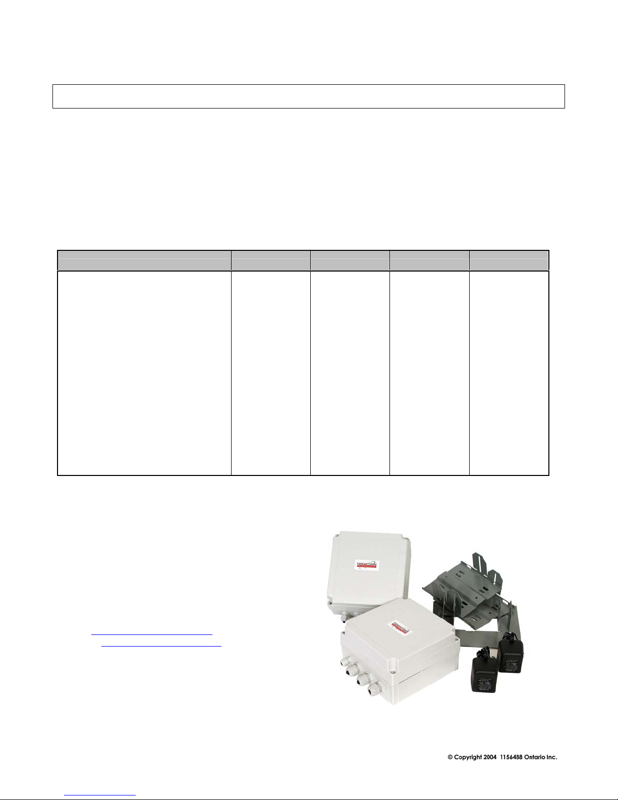
PARTS LIST................................................................................................................. 5
PRE INSTALLATION................................................................................................. 6
Site Evaluation.....................................................................................................................................6
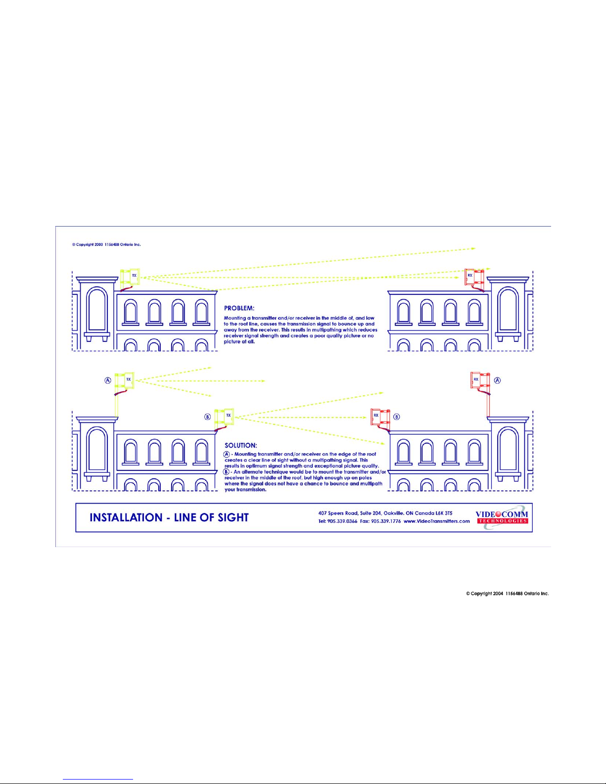
Identify line-of-sight ......................................................................................................................6
Up & in the clear............................................................................................................................6
Ground Plane.................................................................................................................................6
Trees Grow! ................................................................................................................................... 7
Unusual Traffic..............................................................................................................................7
Things that block transmission.................................................................................................... 11
Alignment & GPS Use ................................................................................................................. 11
Tools Required................................................................................................................................... 12
Opening & Closing The All Weather Enclosure .................................................................................. 13
Video Cable Installation & Termination ............................................................................................. 14
Video and Audio Cable Installation & Termination............................................................................. 15
Terminating External Antenna Cable................................................................................................. 16
Terminating External Antenna – Video – Audio Cables..................................................................... 16
Unused Grommet Seals ...................................................................................................................... 17
Power Supply Connection................................................................................................................... 18
Power-Up Device............................................................................................................................... 19
Channel Selection............................................................................................................................... 20
Antenna Polarization.......................................................................................................................... 21
Multiple Link Antenna Polarization .................................................................................................... 24
Conducting a Bench Test.................................................................................................................... 25
INSTALLATION........................................................................................................ 27
Pole Mounting the 5.8GHz All Weather Series.................................................................................... 27
Wall Mounting the 5.8GHz All Weather Series.................................................................................... 30
Enclosure Alignment and Positioning ................................................................................................. 31
TIPS & TROUBLE SHOOTING............................................................................... 32
OPTIONAL PRODUCTS & ACCESSORIES .......................................................... 34
SPECIFICATIONS .................................................................................................... 35
WARRANTY INFORMATION/ TERMS & CONDITIONS.. 36

5.8GHz All Weather 8 Channel Series Manual Rev. J
3
SAFETY NOTICES
I. THIS DEVICE COMPLIES WITH FCC RULES PART 15. OPERATION IS SUBJECT
TO THE FOLLOWING TWO CONDITONS:
(1) This device may not cause harmful interference, and
(2) This device must accept any interference, including interference that
may cause undesired operation of the device
II. In order to comply with the FCC/IC adopted RF exposure requirements, this transmission
system will be installed by an authorized professional installer of VideoComm
Technologies. Installation of all antennas must be performed in a manner that will provide
at least 23cm clearance from the front radiating aperture, to any user or member of the
public.
III. This is NOT an intrinsically safe device. Do not take into area where intrinsic safety is
required. Bodily harm may result if warning is ignored.
IV. DO NOT OPERATE TRANSMITTER WITHOUT ANTENNA CONNECTED TO
ANTENNA PORT. Failure to do so will result in damage to the unit and void the
warranty.
V. DO NOT OPERATE THE TCO-5800 SYSTEM WHEN the Transmitter & Receiver are
closer than ten feet to each other. The devices may not work properly and permanent
damage can occur.
VI. The TCO-5800 has been certified by the FCC for use with other products without any
further certification (as per FCC section 2.1091.) Changes or modifications not expressly
approved by VideoComm Technologies could void the user’s authority to operate the
equipment.
The term “IC:” before the radio certification number only signifies that Industry Canada
Technical specifications were met.

5.8GHz All Weather 8 Channel Series Manual Rev. J
4
INTRODUCTION
Introduction
Designed with the harshest environments in mind, the robust TCO-5808 series delivers high resolution,
real time video in applications ranging from a few hundred feet up to many miles, depending on
system. Its rugged IP-67 all-weather enclosure transmits in applications where trenching cable may not
be possible, convenient or economical. Operating in the unlicensed 5.8GHz ISM band, this unit
features eight user selectable channels and includes a universal mounting bracket system for a variety
of mounting scenarios.
Advantages
• Easy to install and operate.
• 8 user selectable channels.
• Internal Transmitters & Receiver Antennas. ( TCO-5808Q9 has external Rx antenna )
• Delivers high resolution, real time video
• Range from 2000 feet to 4 miles line of sight (depending on system & antenna)
• Less susceptible to wireless data networks and other devices
• Rugged all weather IP-67 protective enclosure.
• Perfect for commercial, industrial, scientific, law enforcement and government video
security applications.
VideoComm Technologies
Customer Service
Bus (905)-339-0366
US Toll Free 888-379-2666
Fax (905)-339-1776
E-mail- info@VideoTransmitters.com
Web Site- www.VideoTransmitters.com
Monday - Friday 8:30am- 5:30pm
Eastern Standard Time

5.8GHz All Weather 8 Channel Series Manual Rev. J
5
PARTS LIST
The 5.8GHz All Weather 8 Channel Series has been carefully manufactured, tested, inspected and
packaged. Please inspect the packaging carefully to ensure you have received all the necessary parts
and accessories listed. Refer to the following chart to determine which parts are included with your
product. If any parts are missing or damaged, contact VideoComm Technologies, Customer Service
or your re-seller immediately.
The TCO-5800 All Weather Video Transmission system comes complete with the following items:
VideoComm Technologies
Customer Service
Bus (905)-339-0366
US Toll Free 888-379-2666
Fax (905)-339-1776
E-mail- info@VideoTransmitters.com
Web Site- www.VideoTransmitters.com
Monday - Friday 8:30am- 5:30pm
Eastern Standard Time
PARTS TCO-5808T3 TCO-5808R6 TCO-5808Q4 TCO-5808Q9
1 X Transmitter Unit X X X X
1 X Receiver Unit X X X X
4 X Grommet Seals Plugs X X X X
8 X Plastic Lid Screws X X X X
2 X Universal Mounting Brackets X X X X
2 X 12VDC 500mA Power Supplies X X X X
3dB Internal Transmit Antenna X X X X
6ft. LMR-200 Antenna Cable OPTIONAL X
6dB Internal Receiver Antenna OPTIONAL X
14dB Internal Receiver Antenna OPTIONAL X
29dB External Receiver Antenna OPTIONAL X

5.8GHz All Weather 8 Channel Series Manual Rev. J
6
PRE INSTALLATION
Site Evaluation
Identify line-of-sight
Although wireless video transmission may seem like a viable option for a particular application at first
glance, there are many considerations. Is there a clear, unobstructed view between the transmitter and
receiver? Are there any other devices that may cause interference? Depending on the height of the
building, tower or structure, you must consider the path that the wireless video will travel between the
transmitter and receiver. Line-of –sight is defined as a clear and unobstructed view between the
transmitter and receiver.
Up & in the clear
To realize the optimum distance for your VideoComm Technologies wireless devices, “give them
some air”. The radio waves coming from your TCO-5800 system antennas do not shoot out like a laser
beam, rather they radiate from the antenna like a flash light beam. Therefore the transmitter and
receiver should both be up and in the clear. A good rule of thumb is to mount the devices at least 15 to
20 feet above obstructions, like the roof of a building, the roofs parked cars in a parking lot, or top of a
fence line.
See Figure 2.
Ground Plane
If the radio devices are not mounted high enough above obstructions, the signal strength will be
seriously reduced; therefore your distance will be reduced. The signal will literately bounce up and
away from your intended target. This is known as a negative ground plane effect. The ground plane
could not only be the ground you stand on, but could also be the rooftops of cars or distant buildings.
See Figure 3.If we have a choice, place the transmitter/receiver enclosures, or if external antenna, on
the edge of the roof looking AWAY from the building, rather than installing them in the middle of the
roof , shooting across the top of the roof. See Figure 4. This is particularly important if we have a
metal roof that tends to deflect signals away from the target. Also consider any obstruction that may
get in the way, like another roof or a tractor-trailer that may pass through your “line of sight”..

5.8GHz All Weather 8 Channel Series Manual Rev. J
7
Trees Grow!
If we install the video link in the winter, the leaves that come out in spring may eliminate your wireless
link. Are you trying to transmit through trees? Then you will need to seriously consider how much
range will be lost. A field test is always the best way to find out. Speak to a VideoComm Technologies
Tech for a possible solution.
Unusual Traffic
Watch out for unusual traffic in your transmission path. For example, a dump truck with the back
elevated while dumping a load can be much taller than expected. Tractor-trailers or other large vehicles
may be a factor if trying to transmit over a highway. Metal obstructions between the antennas cannot
be ignored including electrical transmission lines that may not be obvious in the distance. Each high
voltage wire crossing your path can be the equivalent of transmitting past an eight-foot thick steel pipe.
Microwave towers may look fragile, but they can be as good as or equal to a solid steel door for
blocking transmission.. The higher the transmitter and receiver are in the air, the higher the success
rate.
VideoComm Technologies
Customer Service
Bus (905)-339-0366
US Toll Free 888-379-2666
Fax (905)-339-1776
E-mail- info@VideoTransmitters.com
Web Site- www.VideoTransmitters.com
Monday - Friday 8:30am- 5:30pm
Eastern Standard Time

5.8GHz All Weather 8 Channel Series Manual Rev. J
8

5.8GHz All Weather 8 Channel Series Manual Rev. J
9

5.8GHz All Weather 8 Channel Series Manual Rev. J
10

5.8GHz All Weather 8 Channel Series Manual Rev. J
11
Things that block transmission
Things that block transmission are not always obvious. Here are some of the most
common pitfalls:
• Water, or anything with water in it (people are 98% water). Snow & rain can
reduce your distance.
• Steel, or anything with steel in it---steel-reinforced concrete (rebar) or metal
window screens, or a tool-room cage. Aluminum siding, and energy-saving
foil on the insulation in the walls are sneaky killers for radio waves. Some
metallic paints or metallic wallpapers also block signals.
• Mirrors block transmission, because the “mirror” consists of a metallic
backing on the glass.
• Lead windows will kill radio transmission; also windows that are UV coated
may have thin metal energy-saving film.
• High Voltage transmission lines (physically they look small, but for video
transmission purposes, they might as well be 6-foot diameter metal sewer
pipes.
• Other materials like brick, drywall or wood, will also cut down on the signal,
depending on water content.
Alignment & GPS Use
As the 5.8GHz All Weather 8 Channel Series utilizes directional antennas and it is
important for both antennas to be “looking at each other”. Height of the antennas is also a
factor. The antennas should have no more than a 10-foot variance in height. If the
transmit antenna is 25ft. up high we would want the receiver antenna mounted at
approximately the same heights. This allows for the receiver antenna to receive main lobe
of the transmitted signal.
The longer the wireless video transmission range is, the more critical the alignment of
BOTH antennas. Once we get over a one-mile range, the alignment may well be
measured only in a few degrees, in any direction (up or down, as well as left or right).
Consider using a portable Global Positioning Satellite (GPS) receiver unit to determine
the transmitter and receiver angles accurately. A GPS looks a bit like a hand-held
calculator, and it lets us “learn” the longitude and latitude, relative to a group of satellites
overhead. We can input a value for both the transmitter and for the receiver and then
instruct the GPS to give us the compass bearings between the two points With a GPS
system a 10-mile unit can be aligned faster than a 1-mile unit aligned “by eye”.

5.8GHz All Weather 8 Channel Series Manual Rev. J
12
Tools Required
The 5.8GHz All Weather 8 Channel Series is designed to be “Plug & Play” and simple
to install with minimal tools. The following is a list of recommended tools to setup your
system.
Coaxial Cable Stripper - For preparing video & audio coaxial cable.
Wire Stripper – For preparing alarm input and power wires.
Phillips Screw Driver – Used for unscrewing the front cover of the IP-67 enclosure to gain access to video,
audio, alarm input and power terminations.
Mini Flat Head (Slot) Screw Driver – Used for changing the receiver antennas polarization from horizontal
to vertical. ( if required )
Metric 20mm Socket & Wrench ( Closest Imperial Size – 13/16”) –
Used to tighten or loosen the larger all weather cable glands.
Do not use pliers as they may cause damage to the cable glands
Metric 13mm Socket & Wrench (Closest Imperial Size – 5/8”) –
Used for tightening or loosening the single small all weather cable gland.
Do not use pliers as they may cause damage to the cable glands
Hand Held LCD Monitor – Recommended for verifying video images at input
to transmitter and output from receiver. Perfect for camera angle and focus
adjustment.
Multimeter – Measures voltage output, amperage, resistance and cable continuity.
Do Not Use Pliers - the pliers rigid grip may cause permanent damage to the cable glands on the all
weather IP-67 enclosure.

5.8GHz All Weather 8 Channel Series Manual Rev. J
13
Opening & Closing The All Weather Enclosure
To make all video, audio, alarm input and power terminations we must access the interior of the enclosure by
removing the front cover.
.
.
The front cover can be removed two ways:
1. Loosen screws using the thumb tab screw covers.
- OR -
Use a Phillips or flat head (slot) screwdriver to
loosen the screws.
WARNING!!! When closing the
enclosure do not over-tighten.

5.8GHz All Weather 8 Channel Series Manual Rev. J
14
Video Cable Installation & Termination
Loosen the desired cable gland, also called a grommet,
using a Metric 20mm socket wrench. (Closest Imperial
Size – 13/16” )
Feed the video and audio cable through the cable gland
hole.
VideoComm Technologies recommends the use of RG-
59 or higher grade coaxial cable for video and audio
terminations.
Do not use video / audio cable that is less than ¼ inch in
diameter, as this may not allow a proper seal when the
cable gland is tightened. If a tight seal is not made
between the cable gland and the video cable, there is a
chance of water leaking into the enclosure, causing
serious damage.
The maximum diameter of cable that should be used in
the cable gland is ½ an inch diameter.
IMPORTANT!!! Attach BNC - male connectors to the
video and audio cables after the raw cable has been
fed through the cable gland. The BNC (M) connectors
are to large to fit through the cable gland hole. Be
careful not to damage the rubber seal inside the cable
gland as you feed through your video cable.
Attach BNC (M) connectors to the video and audio
cables. And make terminations to video and audio
bulkhead BNC (F) connectors for the device.
Now using a Metric 20mm socket wrench. ( Imperial
Size – 13/16” ) tighten the cable gland to ensure a
water-tight seal
WARNING!!! If you do not tighten the cable gland, you do not have a watertight seal.

5.8GHz All Weather 8 Channel Series Manual Rev. J
15
Video and Audio Cable Installation & Termination
The following illustration demonstrates power supply, video and two audio cables, connecting through
the different cable glands for the enclosure. This can only be done if using internal factory antennas.

5.8GHz All Weather 8 Channel Series Manual Rev. J
16
Terminating External Antenna Cable
If connecting an external Receiver antenna to your
receiver, Loosen the desired cable gland using a Metric
20mm socket wrench. (Closest Imperial Size – 13/16” )
Feed the end of the RF cable that has the smaller SMA-
Male connector through the grommet.
Carefully thread the RF cable SMA-Male connector
onto the receiver’s SMA-Female bulkhead and tighten.
Now tighten the grommet to seal the cable.
If a tight seal is not made between the cable gland and
the video cable, there is a chance of water leaking into
the enclosure, causing serious damage.
Be careful not to damage the rubber seal inside the cable
gland as you feed through your video cable.
WARNING!!! If you do not tighten the cable gland, you do not have a watertight seal.
Terminating External Antenna – Video – Audio Cables
The following illustration demonstrates multiple
cable inputs for power supply, Video cable,
and a single Audio cable, connecting through
the different cable glands for the enclosure.

5.8GHz All Weather 8 Channel Series Manual Rev. J
17
Unused Grommet Seals
After video and audio cables are installed and terminated you may find there one or more cable glands are
not being used. If there are cable glands not being used this means that water can enter the enclosure, causing
damage. To prevent this from happening, VideoComm includes black plugs to seal off any unused cable
glands.
Turn cable gland counter clock wise to loosen. Use a Metric 20mm
socket wrench. (Closest Imperial Size 13/16”)
From the inside of the enclosure, insert black plugs into
unused cable glands.
Using a Metric 20mm socket wrench (Closest Imperial
Size – 13/16”) turn the cable gland clock wise to tighten; this will
make a watertight seal. Do not over tighten.
IMPORTANT! Failure to tighten the cable gland may result in water
damage, not covered under manufacturer warranty.

5.8GHz All Weather 8 Channel Series Manual Rev. J
18
Power Supply Connection
Inside the enclosure you will find a green
terminal strip with orange terminal lock tabs.
WARNING! Transformer must not be
powered while making connections to the
terminal strip. An electrical short can occur,
causing harmful damage to the unit.
Turn the small cable gland counter clock
wise to loosen. Use a Metric 13mm
wrench. (Closest Imperial Size – 5/8”)
Feed the power cable wire through the
cable gland hole.
Push down the orange lock tabs to open
the terminal input. Insert negative (-)
and positive (+) wire leads as
illustrated. See Figure 5 Release the
orange terminal lock tab. Ensure the
wire is locked tight into the terminal to
avoid an electrical short.
Re-tighten the cable gland to ensure water
tight seal
POSITIVE ( + ) 9 – 14VDC INPUT
NEGATIVE ( - ) 9 – 14 VDC INPUT
IMPORTANT! Failure to tighten the
cable gland may result in water damage,
not covered under manufacturer warranty.
Figure 5

5.8GHz All Weather 8 Channel Series Manual Rev. J
19
Power-Up Device
Assuming that the power supply has been terminated properly inside the transmitter and receiver, plug in the
transformer to an available AC source. The RED LED power indicator light should illuminate.
Check to see that the power switch is turned to the “ON” position. If the LED light does not turn “ON”,
check polarity of the power supply wires as connected into the terminal input and correct.
RED LED will light
when power is “ON”

5.8GHz All Weather 8 Channel Series Manual Rev. J
20
Channel Selection
The TCO-5808 All Weather Series has 8 channel user selectable frequencies. For the wireless video link to
work, both the transmitter and receive must be set to the same channel. On the inside of the transmitter and
the receiver, you will find three dip switches as illustrated. Choose desired channel and set dip switched
accordingly. Ensure both transmitter and receiver have same channel settings.
Frequency PIN 1 PIN 2 PIN 3
Channel # 1 5.733 GHz OFF OFF OFF
Channel # 2 5.752 GHz ON OFF OFF
Channel # 3 5.771 GHz OFF ON OFF
Channel # 4 5.790 GHz ON ON OFF
Channel # 5 5.809 GHz OFF OFF ON
Channel # 6 5.828 GHz ON OFF ON
Channel # 7 5.847 GHz OFF ON ON
Channel # 8 5.866 GHz ON ON ON
ON
OFF
Dip Switches
This manual suits for next models
4
Table of contents