VIDEOMAN VS-902 User manual

VIDEMAN is a registered trade mark of EOS Australia Pty Ltd
Designed, imported and distributed by Videoman Systems Co.
VS-902 B&W 16VDC VS-952 Colour 16VDC
( VS-902M + VS-902C + VS-902PSU ) ( VS-952M + VS-952C + VS-902PSU )
VS-902P B&W 240VAC VS-952P Colour 24VAC
( VS-902PM + VS-902C ) ( VS-952PM + VS-952C )
060911.67 www.videoman.com.au

Indoor Monitor(Ref VS-902M) Installation
Fig. 1
155 Cm
Audio Handset (Ref VS-902H) Installation
Fig. 2
155 Cm
Surface Mount Camera(Ref VS-902C)Installation
4B3Y2W1R LB
155 Cm
Fig. 3
Install indoor monitor, outdoor camera or audio handset about
1.55M~1.60M from the ground and keep away from snow,
rain and direct sunlight.
NOTE : Optional angle brackets are available for surface
mount cameras
45Degree left/right : Ref VS-902AB45
15Degree left/right : Ref VS-902AB15
Page1

Flush Mount Camera (Ref VS-902MC) Installation
Fig. 4
160 Cm
130mm
200mm
175mm
70mm
100mm
Ref. No: VS-902EB
Dimensions
Overall size of front panel :
130mm(W) x 200mm(H)
Cut out size without embedding box:
100mm(W) x 130mm(H) x 60mm(D)
Cut out size for embedding box (Ref VS-902EB):
100mm(W) x 175mm(H) x 70mm(D)
Descriptions of Audio Handset (Ref VS-902H)
1
3
4
5
2
Dimension: 215(H)x80(W)x45(D)
Fig. 5
Descriptions of Power supply (Ref VS-902PSU)
Fig. 6
16V DC 800mA SAA Approved
1. Loud Speaker for Ring Tone
2. “Intercom-Call” button
3. “UNLOCK” button
4. Handset
5. Spiral cord
The adaptor is only supplied with VS-902 and VS-952
( -- ) : Black wire : Surround
( + ) : White Stripe : Centre
For 240V AC model (Ref. VS-902PM, Ref.VS-952PM) connect the
monitor directly to 240V AC mains without 16V DC power supply
(Ref.VS-902PSU)
Page2

Descriptions of Monitor
16VDC Model (Ref.VS-902M B&W, Ref.VS-952M Colour)
240VAC Model (Ref.VS-902PM B&W, Ref.VS-952PM Colour)
10
1
3
4
5
2
9
7
8
6
11
15
14
13
16
19
20
18
12
17
Dimension:220(H)x190(W)x55(D) Fig.7
JP-VD
JP-LK
JS-AP
JS-VP
To Audio Handset
VS-902H
Fig.8
19
15
14
13
21
12
20
1. Screen
2. Power Indicator
3. “MONITOR” button (Refer to Page8)
Press to turn on monitor or switch the second camera if the
second camera is installed with a switcher (Ref:VS-2Way)
4. “UNLOCK” button (Refer to Page8)
5. “INTERCOM” call & Ring tone selection button
(Refer to Page8)
6. Handset
7. Loudspeaker for ring tone
8. Brightness adjustment
9. Contrast (Ref VS-902M/PM) or Colour(Ref.VS952M/PM) adjust
10.Craddle and Hook switch
11. Ringing volume adjust
12. JS-VP 4 pin port to Bracket Board(Ref VS-210W, VS-2Way)
13. JS-AP 3 pin port for Handset (Ref.VS-902H)
This connector is supplied with Ref VS-902H.
14. JP-VD Video impedance setting (Refer to Page5 Note2)
With Jumper : 75 Ωfor the furthest monitor
(factory default is with Jumper)
Without Jumper : High impedance for other monitor(s)
15. JP-LK Unlock operation type setting
(Refer to Note Page4 #7, Page5 Note1,2,3)
With Jumper : Dry contact output from Camera’s
LB terminal (factory default)
Additional power supply is required for door latch with
this type of door latch operation.
Without Jumper : 12VDC Max.500mA output
to door latch from Camera’s LB terminal.
NOTE 1 : During unlock operation the screen will be
off if this mode is selected.
NOTE 2 : Do not use any electric door latch bigger
than 6W with this type of door latch operation.
16. DC input socket (Ref. VS-902M & Ref.VS-952M)
17. AC input cord (Ref. VS-902PM & Ref.VS-952PM)
18. Wall mounting bracket
(Single camera : Ref. VS-210W; Standard )
(With second camera : Ref. VS-2Way , Optional extra)
19. JW-VP wiring terminal to camera(s) & slave monitor(s)
20. JS-VP monitor terminal
21. 4 core connector with plugs (Ref. VS-4P)
Page3

Descriptions of ABS plastic surface mount camera (Ref. VS-902C)
3
5
4
2
2W1R 3Y 4B LB 8
7
6
Dimension: 128(H)x98(W)x43(D)
1
Fig. 9
4B3Y2W1R LB
1
2
3Common - Black
N.O. - Red
N.C. - White
1R +12V DC presents when outdoor station being called or supervised.
2W Ground (GND)
3Y Video signal (1Vp-p)
4B Audio and control signal
1. Camera
2. IR LEDs for night vision
3. Speaker
4. CALL button
5. Microphone
6. Cable terminal to monitor
7. Unlock port LB – The characteristic of this
port out is determined by JP-LK Jumper
on back of monitor (Refer to Page3 #15,
Page5 Note3)
With Jumper : Dry contact output
from Camera’s LB terminal (factory
default)
Without Jumper : 12VDC
Max.500mA output to door latch from
Camera’s LB terminal.
Pin#1 (Top - Red): Normally Open
Pin#2 (Middle-Black): Common
Pin#3 (Bottom-White ): Normally Close
8. Mounting bracket
Descriptions of Stainless Steel Flush mount camera (Ref. VS-902MC)
Overall Dimension (mm):
200(H)x130(W)x50(D)
Cut Out size without embedding box:
100(W) x 130(H) x 60(D)
Cut Out size with embedding box:
175(H)x100(W)x70(D)
LA 2W1R 3Y 4B LB
3
5
4
2
1
Fig. 10
1. Camera
2. IR LEDs for night vision
3. Speaker
4. Call button
5. Microphone
NOTE : This camera can be used with optional
embedding box (Ref.VS-902EB), Refer to Page2.
Page4

System connection with one camera and a monitor IMPORTANT!! Please read page 9 & 10 for cable
requirements BEFORE running cables.
OUTDOOR STATION
VS-902C/MC
VS-952C/MC
* NOTE5
* NOTE1
* NOTE 4
Ref.VS-4P
DC IN
16VDC Power supply
Ref. VS-902PSU
MONITOR
VS-902(P)M
VS-952(P)M
JS-VP
JS-AP
JP-LK : Reserved
JP-VD
BACK
MOUNT BRACKET
4B3Y2W1R LB
POWER SUPPLY
FOR DOOR LATCH
* NOTE 5
Parellel connection to
next Monitor(s)
Fig. 11 Dry contact mode
Fail-Secure
Door Latch
(Ref SL-ST-160)
*Broken line indicates Shield wire if any
OUTDOOR STATION
VS-902C/MC
VS-952C/MC
4B3Y2W1R LB
Fig. 12 : DC output mode
Fail-Secure
Door Latch
(Ref SL-ST-160)
* Note 2
Red wire
*Broken line indicates Shield wire if any
NOTE 1: JP-LK is used for Unlock operation type setting.
(Refer to Note Page4 #7, Page3 #15,)
With Jumper (Dry contact mode) : Dry contact output
from Camera’s LB terminal (factory default)
Additional power supply is required for door latch
with this type of door latch operation.
Without Jumper (DC output mode): 12VDC Max.500mA
output to door latch from Camera’s LB terminal.
During unlock operation the screen will be off if
this mode is selected.
Do not use any electric door latch bigger than 6W
with this type of door latch operation.
NOTE 2 : In DC output mode as above, the Red wire must
be in connected to 1R as Fig 12. Only a fail-secure type
(Normally locked) door lock can be used in this mode.
NOTE 3: LB terminal provides two ways of connection---“Normally Close” and “Normally Open”.
Connect a fail-secure(Normally locked) type door latch (Ref. SL-ST-160) to terminal No.1 & 2.
For a fail-safe(Normally unlocked) type door latch, connect it to No.2 & 3 but only available with Dry contact mode
(An additional power supply (Ref.SE-12VDC05Adpt) is required.)
NOTE 4: For 240V AC model (Ref. VS-902PM, Ref.VS-952PM) connect the monitor directly to 240V AC mains without 16V DC
power supply (Ref.VS-902PSU)
NOTE 5: JP-VD is used for setting the video impedance. When there is only one indoor monitor, keep the jumper (Factory Default),
but when more than one monitor is installed, remove JP-VD Jumper from all other monitors except the last monitor.
Page5

System connection with two cameras and multiple monitors
IMPORTANT!! Please read page 9 & 10 for cable requirements BEFORE running cables.
JW-VP
JS-VP
JS-AP
JP-LK
BACK
MOUNT BRACKET
4B3Y2W1R LB
LB1R 2W 3Y 4B
JS-VP
JS-AP
JP-LK
JP-VD
BACK
MOUNT BRACKET
POWER SUPPLY
FOR DOOR LATCH
Ref SE-12VDC05Adpt
* When using 2 Cameras,
Replace the Connection PCB 210W
with a 2WAY (Ref VS-2WAY) PCB.
VS-905M/952M
240V AC
* NOTE 3
JP-VD
* NOTE 5
* NOTE 1
TO NEXT
MONITOR(S)
VS-905M/952M
Ref VS-210W
OUTDOOR STATION No.1
* NOTE 3
DC IN
*NOTE 4
DC IN
*NOTE 4
To Audio Handset
Ref.VS-902H
To Audio Handset
Ref.VS-902H
Fig. 13
OUTDOOR STATION No.2
Fail-Secure
Door Latch
(Ref SL-ST-160)
Fail-Secure
Door Latch
(Ref SL-ST-160)
* NOTE 5
* NOTE 1
*Broken lines indicate Shield wire
if any
Page6

Video distributor (Ref. GL-D4L-PLUS) for multiple colour monitors
When more than one colour monitor is installed (Ref. VS-952M, VS-952PM) in a system, using a video amplifier (Ref.GL-D4L-PLUS).
This is highly recommended for better image.
JP1
In order to employ the output U5
of the video distributor,remove the
jumper terminal( JP1 ) on the PCB
to 3Y on Monitor #1
to 3Y on Monitor #2
to 3Y on Monitor #3
to 3Y on Monitor #4
to E(Video In) on Next Distributor
Video IN
From 3Y on Call Station
2W(Ground) wires
from Camera & Monitors
MUST connect to
this GND terminals.
Ref.GL-D4L-PLUS
(+) (-)
R2 R1
Ref. SE-12VDC05Adpt
Loop Out
Fig. 14
System connection with audio Handset
JP-VD
JP-LK
JS-AP
JS-VP
INDOOR MONITOR
DC IN
AUDIO HANDSET
VS-902H
MOUNT BRACKET
OUTDOOR STATION
VS-902C
VS-952C
4B3Y2W1R LB
Fail-Secure
Door Latch
POWER SUPPLY
FOR DOOR LATCH
TO NEXT
MONITOR(S)
Fig. 15
Ref.
VS-902PSU
*Broken line indicates Shield wire if any
Page7

Basic Operation
When visitor presses the “CALL” button on the outdoor station, the electronic bell in indoor monitor chimes, at the same time, the screen
displays the visitors’ images.
Pick up the handset, and talk with the visitors for 90 seconds. If nobody answers the phone, the screen will turn off in 30 seconds
automatically. If the system connects more than one indoor monitor – when one handset is picked up, the other indoor monitors will be off
immediately.
Monitoring through indoor monitor
Press “MONITOR” button on indoor monitor, the screen will display the outdoor camera. To turn it off press again or wait in 30 seconds
turn it off automatically.
Monitor adjustment
If desired, the contrast and brightness may be adjusted improve the image and brightness level.
Volume level of the ring tone may also be adjusted by the potential meter at the back of monitor.
Impedance setting is required by JP-VD Jumper at the back of monitor, when more than one monitor is installed.
(Refer to Page5 Note2)
Door latch operation
Click “UNLOCK” button to open the electronic latch during monitoring or talking.
1) Single click will activate the latch for 3 Seconds. For longer door latch operation, press and hold the “UNLOCK” button
2) Door unlock operation type can be setup by JP-LK Jumper on the back of monitor. (Refer to Page3#15, Page4#7 & Page5 Note1,2)
Operation for Intercommunication between monitors/handsets
When system is connected with multiple monitors/handsets, internal intercommunication is available.
An Intercom calling can be started by any indoor monitor. Pick up (off the cradle) the handset and press “INTERCOM” button, other indoor
monitors/handsets will ringing if they are on the cradle, pick up handset to talk between monitors/handsets.
Change of Ring tone by “INTERCOM” button
While the handset is on the cradle, press and hold the “INTERCOM” button for 3 second for ring tone change. Click the button until
desired ring tone for the door bell is heard, then lift the handset and hang up. This setting will be reset to factory default ring tone once
monitors lose its power.
Operation for multiple outdoor cameras
1) When outdoor station calls, the screen will display the view of the visitor automatically and communication is available after picking
up the handset.
2) The indoor monitor can supervise each outdoor station (cameras) in turns. When “MONITOR” button is first pressed, it displays
image from No.1 outdoor camera; Second press of “MONITOR” button will display image from No.2 outdoor camera. Press
“MONITOR” button again to turn the screen OFF.
NOTE: While monitoring or talking, press “UNLOCK” button to open the lock, that is connected to the outdoor camera which is being
monitored.
Page8

Cable requirement – STAR Wiring method
DC IN
VS-902M/952M
MONITOR
4core
Fig8 4core
VS-902C/952C
CAMERA
Fig8
Fig. 16
Fail-Secure
Door Latch
(Ref SL-ST-160)
Fig8
An additional power supply and
Fig8 Cable is required when
JP-LK Jumper is removed.
(Indicated as broken lines of the
diagrams)
Refer to Page3 #15, Page4 #7
and Page5 Note1,2,3 of this
manual.
Fig. 17
DC IN
VS-902M/952M
MONITOR
4core
Fig8 7core
VS-902C/952C
CAMERA
Fig8
Fail-Secure
Door Latch
(Ref SL-ST-160)
Fig8 3core
VS-902H
HANDSET
Cable requirement
Based on the distance from the camera
to the furthest monitor,
< 20M : CAT5 cable
3Y-Video
2W-GND
4B-Audio
2W-GND
1R-12VDC
1R-12VDC
Latch #1
Latch #2
Orange
W/Orange
Green
W/Green
Blue
W/Blue
Brown
W/Brown
Fig8 7core 3core
Fig8
4core
Fig. 18
4core
Fig8
Fail-Secure
Door Latch
(Ref SL-ST-160)
Fig8
CAT5 wire configuration
< 50M :
14/020 (0.44mm2)shielded cable
(connect shield to 2W)
AND
RG-59/U for video signal
(connect core to 3Y & shield to 2W)
12core 3core
Fig8 7core
VS-902M/952M
Monitor with
Ref.VS-2WAY
Fig8
Fig. 19
4core
Fig8
Fail-Secure
Door Latch
(Ref SL-ST-160)
Fig8
Fig8
Fig8
4core
< 100M :
24/020 (0.75mm2)shielded cable
(connect shield to 2W)
AND
RG-59/U for video signal
(connect core to 3Y & shield to 2W)
> 100M :Contact your supplier
NOTE : Fig 8 = 2Core 24/020
( 0.75mm2 /Core)
Page9

Cable requirement – Daisy Chain (loop-in-loop-out) wiring method
DC IN
4core
VS-902M/952M
MONITOR
VS-902C/952C
CAMERA
Fig. 20
Fig8
Fig8
Fail-Secure
Door Latch
(Ref SL-ST-160)
Fig8
DC IN
Fig8
Fig8
Fig8
4core 3core
Fig. 21
Fig8
DC IN
Fig8 Fig8
Fig8
4core 4core 3core
Fig. 22
DC IN
Fig8 Fig8
Fig8
4core 3core
Fig8
Fig8 VS-902M/952M
Monitor with
Ref.VS-2WAY
4core
Fig. 23
Fig8
Fig8
4core
MEMO
Page10

MAINTENANCE
1. All components should be protected from violence vibration, impacting, knocking and dropping.
2. If necessary, clean the lens and screen with dampen soft cotton cloth do not use chemical clean agent.
3. Image distortion may occur if the monitor is installed near microwave ovens, TVs, computers, DC/AC adaptors or any other electro
magnetic field generating appliances.
4. Keep away all monitors and cameras from high temperature, dust, caustic and oxidation gas.
5. Use only the power supply which is supplied by the manufacture.
6. Pay attention to the high voltage inside the products. Please ensure this unit is only serviced by qualified professionals.
TECHNICAL SPECIFICATIONS
1. Talk auto-off time: 90 seconds
2. Power supply for indoor monitor
16V DC : Ref.VS-902M, VS-952M
240 AC : Ref.VS-902PM, VS-952PM
3. Power for outdoor station: 12V DC (Supplied by indoor monitor)
4. Power for video phone (Ref.VS-902H): 12V DC (Supplied by monitor)
5. Power consumption: Standby 0.5W, Max. 15W
6. Indoor monitor screen: 4“ B/W CRT (Ref.VS-902, VS-902PM) or 4” colour TFT LCD (Ref.VS-952M, VS952PM)
7. Camera Lens: 3.6mm, 72 degree horizontal visual angle
8. Image sensor : 1/3” CCD
9. Resolution: >300 TV lines
10. Video signal: 1Vp-p, 75Ω, CCIR standard
11. Connection mode: 4 wire, polarity conscious
12. Surveillance auto-off time: 30 seconds
13. Door latch operation time : 3econds by single click or “press & hold” for longer time
WARRANTY STATEMENT
This equipment is warranted to be free from defects in material and workmanship for a period of twelve months from the date of purchase as indicated on
the proof of purchase and/or by serial number on the product.
Defective units returned by the purchaser at his own expense during this period will be required (or replaced at the option of the distributor) with an
equivalent piece of refurbished and tested equipment. The repaired or replaced equipment is then warranted for the balance of the initial warranty period
or for thirty (30) days, whichever is longer.
The repair or replacement will be without charge provided that the equipment has not been subjected to electrical of physical misuse or to unauthorised
repair or modification.
The foregoing warranty is in lieu of all other warranties, express or implied, including, but not limited to, merchantability or fitness for a particular purpose.
The purchaser's exclusive remedy with respect to any and all losses or damages resulting from any cause whatsoever, shall be repair or replacement as
specified above.
Distributor shall in no event be liable for any consequential or incidental damages, however occasioned, whether by negligence or otherwise. No suit or
action shall be brought against manufacturer more than one year after the accrual of the cause of action therefore. No agent, employee or representative
of the distributor nor any other person is authorised to modify this warranty in any respect. This warranty gives you specific legal rights and you may also
have other rights which vary from state to state.
www.videoman.com.au
This manual suits for next models
9
Table of contents
Other VIDEOMAN Intercom System manuals

VIDEOMAN
VIDEOMAN Futuro 7.1 M User manual

VIDEOMAN
VIDEOMAN BIDP-500 User manual

VIDEOMAN
VIDEOMAN Digital 700 User manual

VIDEOMAN
VIDEOMAN FUTURO-A4 User manual

VIDEOMAN
VIDEOMAN FUTURO-SD4B User manual

VIDEOMAN
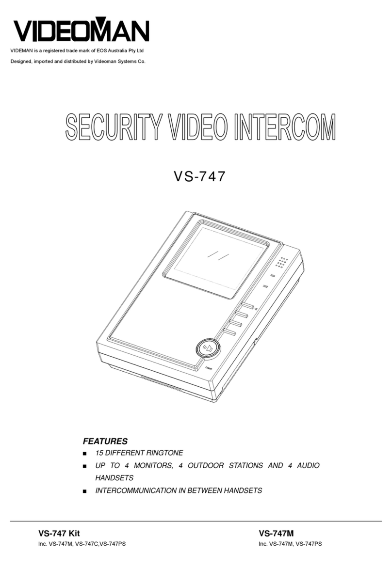
VIDEOMAN VS-747, VS-747M, VS-747C, VS-747PS User manual

VIDEOMAN
VIDEOMAN futuro-iron7m User manual