Linear BP-2001 User manual

Page 1 of 11
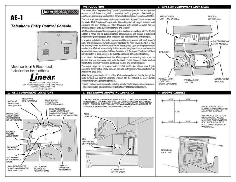
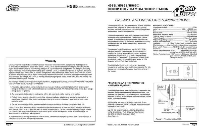
BP-2001
RPL 2000 1-Channel Beltpack
Operating
Instructions

Page 2 of 11
1 General................................................................... 3
2 Setting up................................................................ 3
2.1 Front view ........................................................... 3
2.2 Rear view ............................................................ 4
2.3 Control elements and connectors ...................................... 4
2.4 Connecting the beltpack to a Riedel Party Line (RPL) ................. 5
3 Operation................................................................. 5
3.1 Talk ................................................................. 5
3.1.1 Talk key properties .............................................. 5
3.1.2 Talking to the intercom channel .................................. 5
3.2 Listen ............................................................... 5
3.3 Call Light ........................................................... 5
3.3.1 Sending a call light signal ...................................... 5
3.3.2 Receiving a call light signal .................................... 6
3.3.3 Buzzer ........................................................... 6
3.4 S-CALL key “S” ....................................................... 6
3.5 Sidetone trimmers .................................................... 6
3.6 Mic Kill ............................................................. 6
4 Programming............................................................... 7
4.1 Programmable options ................................................. 7
4.2 Programming modes .................................................... 8
4.2.1 Examples ......................................................... 8
5 Connecting Options........................................................ 9
5.1 Headset: ............................................................. 9
5.2 Intercom Line Connector .............................................. 9
5.2.1 Intercom line connector in RPL Mode .............................. 9
5.2.2 Intercom line connectors in Clear-Com-Mode...................... 9
6 Technical Data........................................................... 10
6.1 Intercom Line ....................................................... 10
6.1.1 Signalling ...................................................... 10
6.2 Mic Preamp .......................................................... 10
6.3 Output Amp .......................................................... 10
6.4 Power Consumption ................................................... 11
7 Warranty…………………………………………………………………………………………………….10

Page 3 of 11
1General
The BP-2001 is an attractive single channel beltpack in a modern design and
with an impact-proof plastic housing. During the design phase, particular
attention was paid to easy access of the controls and the visibility of the
call light in practical use. Marks on the keys and the layout of the controls
enable “blind” operation. The volume control is mounted on the side for ease
of operation. The talk key is marked and include an LED indicator. The call
light has a particularly large design, thus guaranteeing the required
visibility. Apart from the call light, the beltpack also features an S-CALL
button. With the BP-2001 you can now also talk to the radio users or switch
to the paging system for announcements directly from the beltpack.
Connection is established via a 3-pin XLR with loop-through, and a 4-pin XLR
is used for the headset. The BP-2001 can be pre-programmed depending on the
application, i.e. a buzzer can be activated in addition to the call light.
The BP-2001 is compatible with ASL, Clear-Comand RTS/TelexSystems.
2Setting up
2.1 Front view

Page 4 of 11
2.2 Rear view
2.3 Control elements and connectors
The BP-2001 is a single-channel beltpack and therefore has one talk key and a
volume control. The talk key is
labelled “I”.
The call light key is marked with the letter “L“ and also located at the
front of the unit.
To activate the S-CALL, there is a key marked “S” underneath the volume
control on the right-hand side of the unit.

Page 5 of 11
On the right, next to the talk key is the channel indicator LED. It tells you
whether the talk key is activated or not.
The call light indicator is located on the top of the housing.
On the underside of the unit, you will find the XLR connectors for connecting
and looping through the intercom line (3-pin), as well as a 4-pin XLR for the
headset.
On the back of the unit are two sidetone trimmers, the BP-2001 only uses the
upper one.
2.4 Connecting the beltpack to a Riedel Party Line (RPL)
The beltpack is a portable headset station powered through the intercom
wiring using the PS-2002 or PS-2004 power supply.
The beltpack is connected to the party line via a 3-pin XLR plug and is ready
for use immediately. The headset is connected via the 4-pin XLR male headset
connector.
3Operation
3.1 Talk
3.1.1 Talk key properties
The Talk key has touch and latch function. Pressing the key briefly
represents the latch function for switching on and off. If the key is held
down for a longer period, the touch function will be activated. In this case,
the Talk function will be active for as long as the key is held down.
3.1.2 Talking to the intercom channel
Press Talk key “I” to talk to intercom channel I. The active Talk function is
indicated by the corresponding LED.
3.2 Listen
A volume control is provided on the right-hand side of the unit. To increase
the volume, rotate the knob clockwise.
Note: If the headset is put down and the Talk function is active, depending
on the volume of the headset, feedback can occur. Therefore, before putting
the headset down, always switch off the Talk function. Activated Talk keys
can be switched off remotely using the “Mic Kill” function on the MS-2004 and
MS-2002 master stations.
3.3 Call Light
3.3.1 Sending a call light signal
You can only send a call light signal to a channel where the Talk function
has been activated. If the channel is switched to “Talk”, the corresponding
LED indicator lights up. By pressing the call light key marked “L”, the call
light signal is sent to the intercom line. The call light illuminates on all

Page 6 of 11
beltpacks in the party line unless it has been suppressed by beltpack-setup.
Your own call light will also be illuminated for the duration of the call.
3.3.2 Receiving a call light signal
If the beltpack receives a call light signal from the party line, the call
light will be illuminated. If the Talk function of the beltpack is not
active, the channel LED indicator flashes.
3.3.3 Buzzer
By programming the beltpack, you can switch in an acoustic signal in addition
to the call light signal. This causes a buzzer in the beltpack to sound if a
call light signal is received. The buzzer is not activated in the factory
default setting. If the buzzer is activated and the beltpack receives a call
light signal, you can mute the buzzer by pressing the S-CALL key. The buzzer
will sound again with the next call light signal received. Pressing the S-
CALL button during a call light to mute the buzzer does not trigger an S-
CALL, but only deactivates the buzzer. It is only if the S-CALL key is
pressed yet again that an S-CALL is sent to the activated channel.
3.4 S-CALL key “S”
You can only send an S-CALL to a channel where the Talk function has been
activated. If the channel is switched to “Talk”, the corresponding LED
indicator lights up. By pressing the S-CALL key marked “S”, a “Special Call”
is generated and sent to the intercom line. It switches a relay in the MS-
2004 master station and in the IF-2004 2/4-wire interface for the duration of
the key-press.
By using the appropriate relay in the MS-2004 master station or IF-2004 4-
wire interface, you can, for example, key the transmitter of a radio base
station to talk to radio users or switch to a paging system for an
announcement, turn on a cue-light etc.
3.5 Sidetone trimmers
On the back of the unit are two sidetone trimmers, one above the other. The
top trimmer is responsible for setting the talk-back (sidetone) for Channel
I. The trimmer underneath is not used with the BP-2001.
You can adjust the talk-back from the user’s own microphone to the headset
earpieces to suit the requirements of the user using the sidetone trimmer.
To avoid malfunction please make sure that the control is not right up to the
left-hand stop.
3.6 Mic Kill
The beltpack detects the Mic Kill signal (sent from a master station) to turn
off the active Talk function. In this way it is possible to switch off all
open microphones on the particular channel from the master stations.
Page 7 of 11
4Programming
4.1 Programmable options
If the intercom supply is applied, the BP-2001 can be programmed to special
operating conditions in which the unit can be used. If the intercom power
supply is switched off or the unit is unplugged, the programming remains in
memory.
In Service Mode, the following settings are available:
Mode No. Clip label Explanation Default setting on
delivery (LED
indicator
illuminated = On)
1 Mic Electret A/B-power for electret microphone
provided Off
2 Mic Gain Microphone amplification increased
by +6dB Off
3 Channel
Assign A Beltpack channel assigned to RPL intercom
Channel A (I)
(Off: beltpack channel assigned to RPL
intercom Channel B (II) )
On
4 Buzzer Acoustic signal with call light
enabled Off
5 Call Enable call light function On
6 S-CALL A Enable S-CALL function On
7 CC-Mode
Clear-Com-compatible mode
activated Off (RPL)
8 Enable automatic latching function
of Talk key On

Page 8 of 11
4.2 Programming modes
Proceed as follows to either check or set up modes:
-Switch off Talk function.
-Then simultaneously hold down the keys call light (L) and S-CALL (S).
-Next press the Talk key 5 times in succession. The buzzer sounds once.
Service mode is now active. Now release the call light and S-CALL keys.
-With the call light key L, step through the menu list. Pressing once
displays the next menu item. You can also press the L key a number of
times to go direct to the required menu item. The current menu item is
signalled by the sounding of the buzzer in the frequency of the item
selected.
-You can change the setting of the current menu item by pressing the S-CALL
key “S”. The channel indicator displays the setting, i.e. an activated
menu item is indicated by an LED that is lit up.
-If all settings are made, by pressing Talk key I, you exit Service mode
and the settings are saved. Saving and exiting are possible at any time.
4.2.1 Examples
-Switch off Talk function.
-Then simultaneously hold down the keys call light L and S-CALL S.
-Next press the Talk key 5 times in succession. The buzzer sounds once.
Service mode is now active. Now release the call light and S-CALL keys.
-Press the “L“ key once, then after about 500ms, the buzzer sounds once.
You are now in Service mode Position 1 (Mic Electret).
-Press the “L“ key twice, then after about 500ms, the buzzer sounds four
times. You are now in Service mode Position 4 (Buzzer B).
-Press the “L“ key five times, then after about 500ms, the buzzer sounds
nine times. You are now in Service mode Position 9 (Call A).
-Press the “L“ key six times, then after about 500ms, the buzzer sounds
twice. You are now in Service mode Position 2 (Mic Gain).
-You can change the current setting of the menu item by pressing the S-CALL
key “S”. The channel indicator displays the setting, i.e. an activated
menu item is indicated by an illuminated LED.
-If all settings are made, by pressing Talk key I, you exit Service mode
and the settings are saved. Saving and exiting are possible at any time.

Page 9 of 11
5Connecting Options
5.1 Headset:
4-pin XLR-male for headset with dynamic or electret microphone
Pin Definition
1 GND
2 Microphone high
3 Loudspeaker low
4 Loudspeaker high
5.2 Intercom Line Connector
At this point, it is important to observe the different modes for RPL and
Clear-Com. In RPL mode, two channels are available on a 3-pin XLR connector.
Using the service mode you can select on which RPL intercom channel the BP-
2001 single channel beltpack will work. In CC mode, by contrast, pin 2 is
used only for the supply voltage of 30 VDC+. No audio is provided on pin 2.
The intercom connectors are looped through. Accordingly, pin 1 (female) is
connected to pin 1 (male), and so on.
5.2.1 Intercom line connector in RPL Mode
3-pin XLR male and XLR female
Pin Definition
1 Ground
2 Audio channel B and +30 VDC
3 Audio channel A
Audio channel B is only used if the BP-2001 is assigned to RPL intercom
channel B (II). This is not the default setting and must be configured using
the beltpack´ s service mode if required.
5.2.2 Intercom line connectors in Clear-Com-Mode
3-pin XLR male and XLR female
Pin Definition
1 Ground
2 +30 VDC
3 Audio

Page 10 of 11
6Technical Data
6.1 Intercom Line
Line Impedance: 200
Line Level: -12 dBu up to +6dBu maximum
Wire Type: 0,38 mm2(AWG 22), 2 conductor shielded mic
cable with <65pF/m
capacity and <70/km overall DC resistance
Line Length (single channel): up to 5000m
Signal to Noise, Single-Channel: -70dBu
6.1.1 Signalling
RIEDEL Mode:
Call Signal Send/Receive: 20 kHz 500 Hz Sine wave, appr. –12dBu
Special Call Signal Send/Receive: 28 kHz 500 Hz Sine wave, appr. –
12dBu
Mic Kill Signal Send/Receive: 24 kHz 500 Hz Sine wave, appr. –12dBu
Clear-ComMode:
Call Signal Send: +11 VDC
Call Signal Receive: +4 VDC
6.2 Mic Preamp
Mic Impedance: 200
Headset Mic: dynamic or electret with +6 VDC supply
Mic Gain: 40dB or 46dB (selectable via service mode)
Limiter Range: 20dB
6.3 Output Amp
Headset Output Level: +20 dBu / 600 maximum
Headset Impedance: > 50 (recommended 600 for low power
consumption)
Gain: 32dB

Page 11 of 11
6.4 Power Consumption
BP-2001 beltpack 22 mA, avg., channels activated
7Warranty
This equipment is under warranty for 24 month from the date of delivery
unless otherwise specified.
All equipment found to have manufacturers defects or defects resulting from
normal use within the warranty period will be repaired at no cost.
The warranty is null and void if repairs or modifications are made on the
equipment by the purchaser or a third party not authorized by LINEAR
TECHNOLOGIE.
Damages resulting from inappropriate use or handling, incorrect installation
or storage, or inappropriate connection are not covered by the warranty.
Table of contents
Other Linear Intercom System manuals

Linear
Linear dmcMP3 User manual

Linear
Linear ACCESS AE-100 Guide User manual

Linear
Linear AE-1 User manual

Linear
Linear M&S VMC1 User manual

Linear
Linear ACCESS AE-100 Guide Technical specifications

Linear
Linear 2GIG-DBELL1-345 Configuration guide

Linear
Linear DMC-10AWP User manual

Linear
Linear DMC1 User manual

Linear
Linear RE-1 User manual

Linear
Linear AM-KP User manual

Linear
Linear Open House H585 User manual

Linear
Linear AE-1000 User manual

Linear
Linear M&S VMC1 User manual

Linear
Linear AE-500 User manual

Linear
Linear AE-500 User manual

Linear
Linear DMC1 User manual

Linear
Linear ACP00937 Technical specifications

Linear
Linear M&S DMC-10DS User manual

Linear
Linear TE Instruction sheet