Videoswitch Vi-P14 User manual

Video Processor
User Manual
Product ranges covered by this manual
Vi-P14
Vi-P14A Vi-Q4C1
Document Reference Date Firmware
Viq601a.doc 26/11/2009 From Viq001a21
Videoswitch Telephone 01252-851510
Ocean House, Redfields Industrial Park Fax 01252-851296
Hants GU52 0RD Web www.videoswitch.co.uk
IntelligentSecurityandFireLtd

Viq601a.doc
IntelligentSecurityandFireLtd

Video Processor
Contents:
1Start Here ..................................................................1
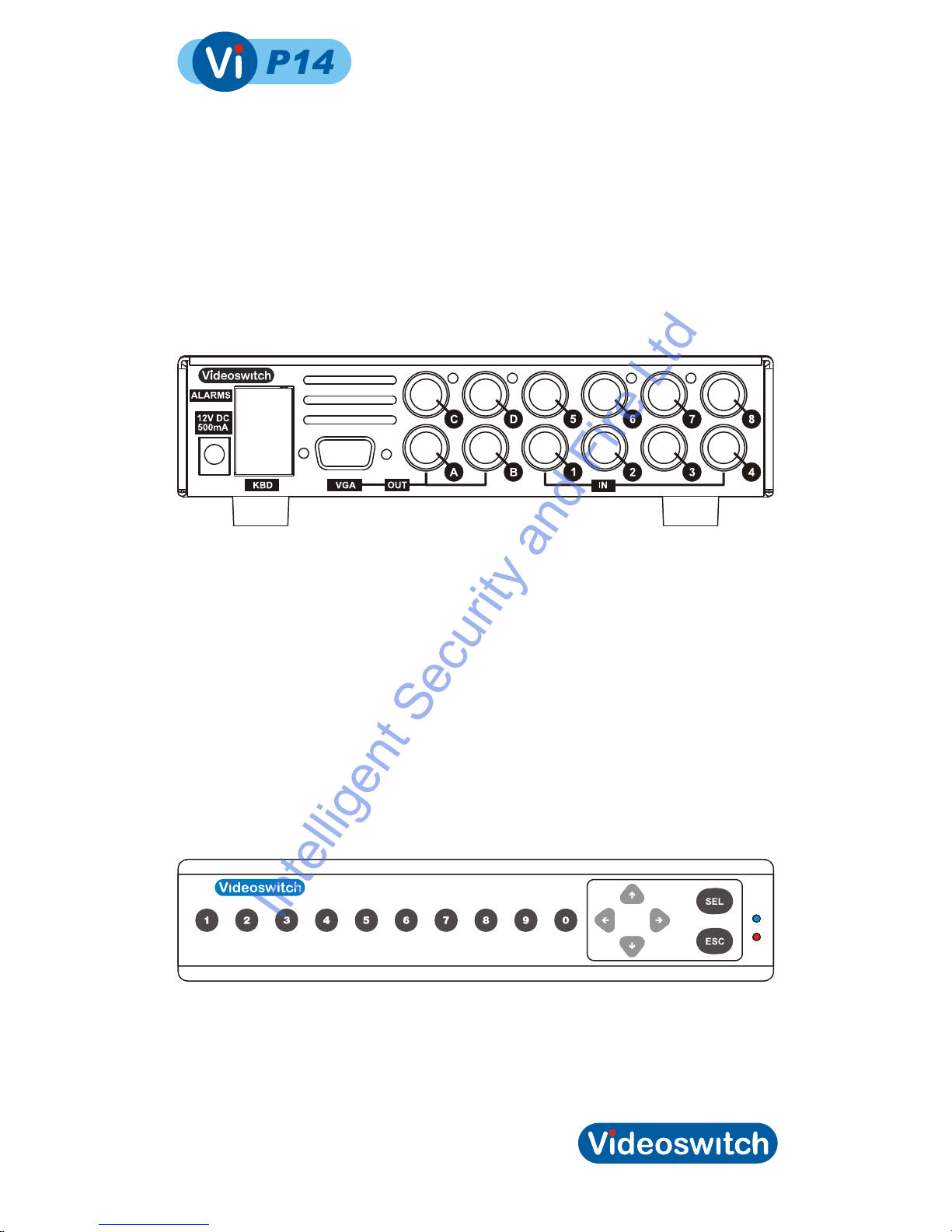
1.1Connecting Up .......................................................................................................................2
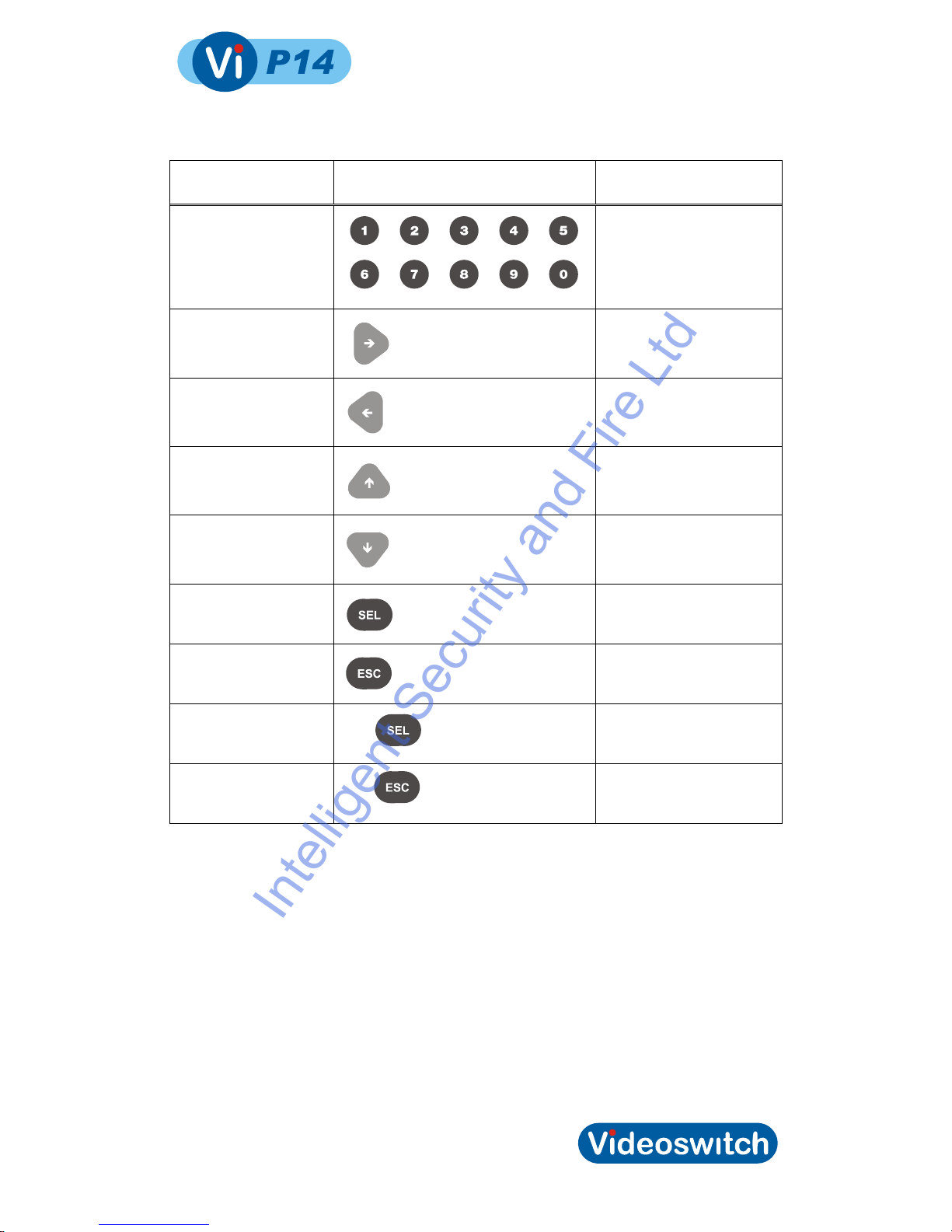
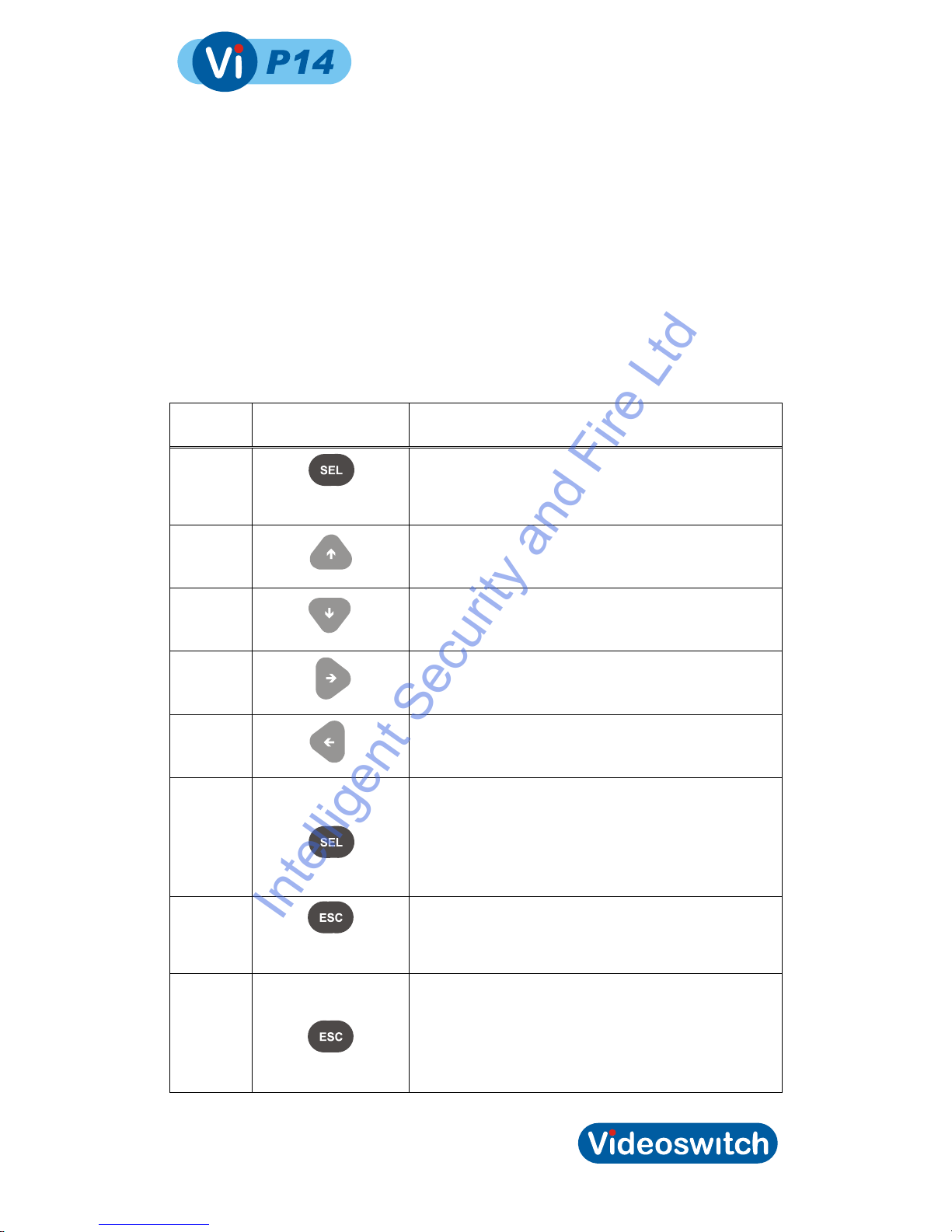
1.2Keypad...................................................................................................................................2
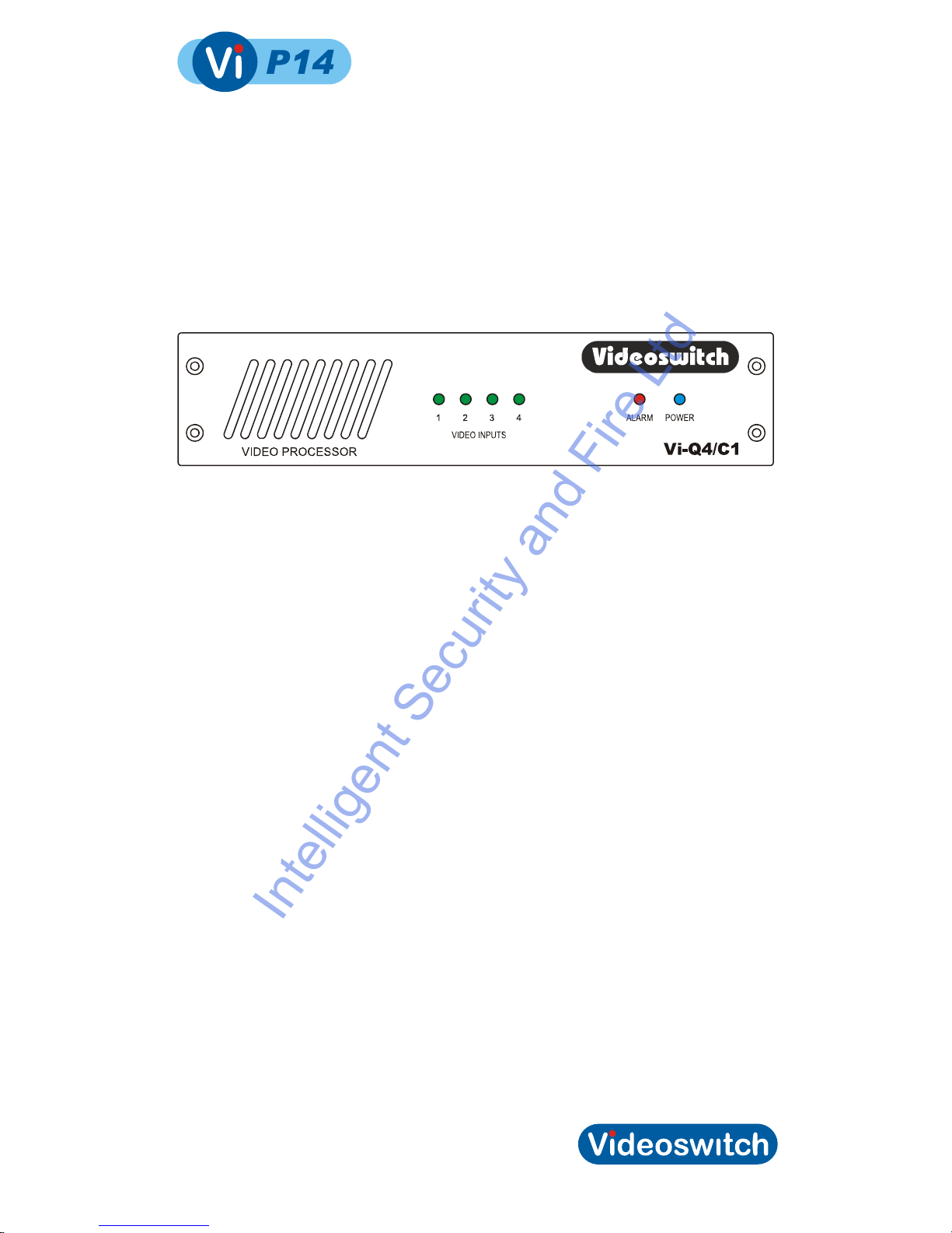
2Front Panel................................................................4
2.1Leds .......................................................................................................................................4
3Menus........................................................................5
3.1Login ......................................................................................................................................6
3.2System...................................................................................................................................6
3.2.1Datetime.............................................................................................................................6
3.2.1.1Enter Datetime .................................................................................................6
3.2.1.2Daylight Saving ................................................................................................6
3.2.1.3Show Datetime.................................................................................................6
3.2.2Vga Mode...........................................................................................................................6
3.2.3Language...........................................................................................................................6
3.2.4Restore Factory Defaults ...................................................................................................6
3.3Display ...................................................................................................................................7
3.3.1Format................................................................................................................................7
3.3.2Image Positions .................................................................................................................7
3.3.3Title Positions.....................................................................................................................7
3.3.4Selectable Formats............................................................................................................8
3.3.5Text Background................................................................................................................8
3.3.6Image Borders ...................................................................................................................8
3.3.7Titles ..................................................................................................................................8
3.3.7.1Unit Title ...........................................................................................................8
3.3.7.2Camera1 Title...................................................................................................9
3.3.7.3Camera2 Title...................................................................................................9
3.3.7.4Camera3 Title...................................................................................................9
3.3.7.5Camera4 Title...................................................................................................9
3.4ALARMS ................................................................................................................................9
3.4.1Pull Up ...............................................................................................................................9
3.4.2Relay Time.........................................................................................................................9
3.4.3Video Loss Mask................................................................................................................9
3.5CONFIG...............................................................................................................................10
3.5.1Lock Keypad ....................................................................................................................10
3.5.2Termination......................................................................................................................10
3.5.3Password .........................................................................................................................10
3.5.4Transmit Config................................................................................................................10
3.5.5Restore Factory Settings .................................................................................................10
4Connections............................................................11
5Technical Data........................................................12
5.1.1Remote Keyboard (lower connector) ...............................................................................12
5.1.2Alarms (upper connector) ................................................................................................12
5.2Specifications.......................................................................................................................13
5.2.1Vi-P14 Screen Modes......................................................................................................13
5.2.2Vi-P14A Additional Screen Modes...................................................................................13
5.2.3Vi-Q4C1 Screen Modes...................................................................................................13
5.2.4Video Processing.............................................................................................................13
5.2.5Display .............................................................................................................................14
5.2.6Control and Interface .......................................................................................................14
5.2.7Power, Physical & Environmental....................................................................................14
5.2.8Upgrades .........................................................................................................................14
i
IntelligentSecurityandFireLtd

Video Processor
5.2.9CE Marking ......................................................................................................................16
5.2.10Ventilation........................................................................................................................16
5.2.11Safety...............................................................................................................................16
ii
IntelligentSecurityandFireLtd

Video Processor
1 Start Here
•The Vi-P14, Vi-P14A and Vi-Q4C1 are quad video processors
•These products accept analogue video inputs from up to four cameras or other
video sources
•Each video input can be scaled, cropped, mirrored, positioned and then combined
on the analogue video output
•A VGA output is provided on the Vi-P14 and Vi-P14A for driving any VGA enabled
monitor or TV
•Menus allow the user to configure the unit
•Configuration may also uploaded and downloaded using a PC
•The Vi-P14A and the Vi-Q4C1 have fully user-programmable screen formats
•The Vi-Q4C1 has additional features aimed at transport applications, including
video presence status LEDs, video loss alarming, special screen formats for
platform monitoring and additional status monitoring software for high reliability
operation in critical applications.
•Alarm inputs are provided that may be used for full screen pull-up
•Software updates may be installed via RS485 from a PC running Vi-SA1
Configuration Manager.
Note:
This manual covers a range of products and therefore describes features that do not exist in
all models.
1
IntelligentSecurityandFireLtd

Video Processor
1.1 Connecting Up
For a standard digital recording system you will need
•The Vi-P14, Vi-P14A or Vi-Q4C1 Video Processor
•Some cameras with lenses
•A video monitor (with BNC composite video input) or a VGA monitor
•BNC cables
•Connect the monitor output (MAIN) of the Video Processor to a Video Monitor using
a BNC cable
•Make sure that the monitor termination is switched on (i.e. to 75 Ohms)
•Connect a camera to Camera Input 1 on the Video Processor using a BNC cable
•Connect further cameras to Inputs 2,3,4 etc
•Connect the mains power using the mains cable provided
1.2 Keypad
The Vi-P14 and Vi-P14A have a mini-keypad with the key layout as above. All functions can
be controlled by the 16 keys provided. Two additional functions are provided by holding
down the SEL key for 1 second or the ESC key for 1 second.
2
IntelligentSecurityandFireLtd

Video Processor
Names of keys used
in this manual Keypad legend Used for
number Select cameras and enter
numbers when in the menu
right
Select next screen format,
navigate in menu
left
Select prior screen format,
navigate in menu
up
Select next input for spot
monitor, navigate in menu
down
Select prior input for spot
monitor, navigate in menu
SEL
Enter menu or select or
confirm within the menu
ESC
Escape from current menu
level to prior level
DEFAULT Hold for 1 second Set a menu setting to default
value
EXIT Hold for 1 second Exit from menu
3
IntelligentSecurityandFireLtd

Video Processor
2 Front Panel
The Vi-Q4C1 has a front panel with LEDs to indicate important status information. Note that
this model requires a PC or Vi-K1 Remote Keyboard to access the menus or change screen
modes.
2.1 Leds
Video Inputs 1,2,3,4 The green video input LEDs illuminate when video is present on the
corresponding camera inputs
Alarm The red alarm LED illuminates when an alarm condition is detected.
Alarm conditions include video loss, external alarms and system
malfunction
Power The power LED indicates that DC power is being supplied to the
unit
4
IntelligentSecurityandFireLtd

Video Processor
3 Menus
•The menu system in this Video Processor allows many aspects of it operation to be
customised to suit a specific installation
•Note that not all menus options described below are available on some models
•The factory defaults may be restored at any time via the CONFIGURATION menu
The keys listed below refer to the built-in keypad. If you are configuring using the Vi-SA1
Configuration Manager software, the keys are the same except dedicated DEFAULT and
EXIT keys are provided.
Key
name Key legend Action
SEL
Enter the menu system. Select an item for editing and
also confirm changes
Up
Select the prior menu item or scroll a value when
editing
Down
Select the next menu item or scroll a value when
editing
Right
Go a level deeper into the menu or move cursor when
editing
Left
Come out of a level in the menu or move cursor when
editing
DEFAULT
Press and hold for 1
second
Set the default setting of a menu item
ESC
Escape from a menu level or escape from editing a
value without saving
EXIT
Press and hold for 1
second
Leave menu completely. Any changes will be saved.
5
IntelligentSecurityandFireLtd

Video Processor
3.1 Login
Some parts of the menu are password protected. Enter the password here to gain access to
the menu.
•Use left and right to move the cursor
•Use up and down to select the digits
•Use left or ESC to exit this menu item
A message on the screen will indicate if you have logged in successfully. A timer keeps you
logged in while you are pressing keys. After a period if inactivity, you will be logged out. You
may manually log out by changing the password to an invalid value (e.g. all zeros). The
default password is: 111100.
3.2 System
3.2.1 Datetime
3.2.1.1 Enter Datetime
Press SEL to start editing the date and time.
Enter the current date and time using the number keys.
Use the left and right keys to move between the digits as required if you do not want to re-
enter the whole date and time.
The date/time format is DD/MM/YY HH:MM:SS.
Press SEL when you have finished editing the date and time, or press ESC to cancel.
Battery backup ensures that the clock continues working even when power is removed for
short periods of time
3.2.1.2 Daylight Saving
If you select the daylight saving option, the clock automatically moves forwards an hour
during March and back an hour in October for daylight saving. No adjustment by the user is
required when the clocks change. The times and dates suit most European countries.
3.2.1.3 Show Datetime
This option determines whether the dat and time is displayed on the screen.
3.2.2 Vga Mode
This menu item allows the VGA output format to be set to suit the connected VGA monitor.
Choose the resolution to get the best results from the connected VGA monitor.
3.2.3 Language
Select from available languages using this option.
3.2.4 Restore Factory Defaults
If you wish to restore all screen formats and other settings the factory defaults, select Yes in
this menu option.
6
IntelligentSecurityandFireLtd

Video Processor
3.3 Display
3.3.1 Format
Prior to editing image positions of title positions, select the screen format that you wish to
edit.
3.3.2 Image Positions
•Use the number keys 1, 2, 3 and 4 to select the camera for which you wish to
adjust the image position.
•Use the up and down keys to select which field you wish to edit
•Use the left and right keys to edit the number in the selected fields
•Use DEFAULT to restore the factory defaults of the selected screen format
•Repeat for other cameras
•Press ESC to exit this screen back to the menu
The image parameters that can be adjusted are:
Field X range Y range Comments
Visible YES or NO Determines whether the camera image is
displayed
Top Left 0 to 176 0 to 142 Position of the top-left corner of the
displayed camera image
Bottom Right 0 to 176 0 to 142 Position of the bottom-right corner of the
displayed camera image
Scale 0 to 255 0 to 255 The scale of the displayed image relative
to the input image (255 represents 1:1)
Offset 0 to 176 0 to 142 The position in the input image that
becomes the top-left of the display
image.
Mirror YES or NO YES or NO Set to YES if you want the image to be
mirrored horizontally, vertically or both.
Note:
•The coordinate X=0, Y=0 represents the top-left of the image.
•X-coordinates refer to the horizontal, larger numbers being further to the right
•Y-coordinates refer to the vertical, larger numbers being further to the bottom
3.3.3 Title Positions
•Use the number keys 1, 2, 3 and 4 to select the camera for which you wish to
adjust the image position.
7
IntelligentSecurityandFireLtd

Video Processor
•Use the number keys 9and 0 to select the Date/Time and Unit title
•Use the up, down, left and right keys to move the selected title to the desired
location on the screen.
•Note that the down key moves the title down by 8 steps whilst up moves it up by
just 1 step. This arrangement allows fine control of the vertical position without
requiring too many key presses.
•Use DEFAULT to restore the factory defaults of the selected screen format
•Repeat for other cameras
•Press ESC to exit this screen back to the menu
Field X range Y range
Camera Title 0 to 57 0 to 144
Unit Title 0 to 57 0 to 144
Date/Time 0 to 57 0 to 144
•The coordinate X=0, Y=0 represents the top-left of the image.
•X-coordinates refer to the horizontal, larger numbers being further to the right
•Y-coordinates refer to the vertical, larger numbers being further to the bottom
3.3.4 Selectable Formats
Screen formats may be selected from the keypad by pressing the number keys or the left
and right keys. This menu option allows you to specify which formats you want to be able to
select.
•Use left and right to move choose the format
•Use up and down to specify whether you want the format to be selectable from the
keypad or not. A solid block indicates a format can be selected whereas a dash
indicates that it cannot.
3.3.5 Text Background
You can choose whether the text is surrounded by a solid block of black or blue background
colour or just a thin border (to ensure the text can be ready whatever the colour of the video
image).
3.3.6 Image Borders
Each camera image may be surrounded by a black or white border, or no border.
3.3.7 Titles
3.3.7.1 Unit Title
The Video Processor may be given a unit title that is displayed on the screen at all times.
•Use left and right to move the cursor
•Use up and down to select the character
8
IntelligentSecurityandFireLtd

Video Processor
•Use DEFAULT to default or clear the title
3.3.7.2 Camera1 Title
Each camera may be given a title that is displayed on the screen whenever that camera
image is displayed.
•Use left and right to move the cursor
•Use up and down to select the character
•Use DEFAULT to default or clear the title
3.3.7.3 Camera2 Title
See above
3.3.7.4 Camera3 Title
See above
3.3.7.5 Camera4 Title
See above
3.4 ALARMS
3.4.1 Pull Up
This setting determines whether an alarm input 1, 2, 3 or 4 will cause formats 1, 2, 3 or 4
respectively to be called up.
3.4.2 Relay Time
When an alarm occurs the relay operates. This option specifies for how the relays remains
active after the alarm condition has ceased.
3.4.3 Video Loss Mask
This mask determines which input are monitored for video loss.
•Use left and right to move the cursor
•Use up and down to select whether the input is to be monitored for video loss. A
solid block indicates that monitoring is ON. A dash indicates that monitoring is OFF.
•Use DEFAULT to default the monitoring settings to all on or all off.
9
IntelligentSecurityandFireLtd

Video Processor
3.5 CONFIG
3.5.1 Lock Keypad
If you do not want the user to be able to select screen formats or cameras, set this option to
YES. To change screen format you now have to enter menu, enter password and change
the screen format in the Format menu.
3.5.2 Termination
Select here whether you want each camera input to be terminated with 75 Ohms. The
default is termination ON.
•Use left and right to move the cursor
•Use up and down to select termination. A solid block indicates that termination is
ON (75 Ohms). A dash indicates that termination is OFF (high impedance)
•Use DEFAULT to default the termination settings to all ON.
3.5.3 Password
The default password (111100) may be changed in this menu.
3.5.4 Transmit Config
This menu option allows the whole menu configuration to be transmitted via the RS485
output. If you are using the Vi-SA1 configuration manager software, it is not necessary to
use this option as the software requests the configuration automatically.
3.5.5 Restore Factory Settings
Set this option to Yes if you want to default all settings including screen formats to the
factory defaults.
10
IntelligentSecurityandFireLtd

Video Processor
4 Connections
This shows a typical example of the video and power connections required. The spot
monitor is optional. The second row of BNC connectors may be used for loop-through.
11
IntelligentSecurityandFireLtd

Video Processor
5 Technical Data
5.1.1 Remote Keyboard (lower connector)
Physical: RJ45
PIN1 PIN8
Electrical: RS485
Pin Number Signal
1 RS485 Input+ (A)
2 RS485 Input- (B)
3 RS485 Output+ (A)
4 +9V output for Keyboard
5 GND
6 RS485 Output- (B)
7 Not used
8 Not used
5.1.2 Alarms (upper connector)
Physical: RJ45
PIN1 PIN8
Electrical: RS485
Pin Number Signal
1 Alarm Input 1
2 Alarm Input 2
3 Alarm Input 3
4 Alarm Input 4
5 GND
6 Relay COM
7 Relay N/O
8 Relay N/C
12
IntelligentSecurityandFireLtd

Video Processor
5.2 Specifications
5.2.1 Vi-P14 Screen Modes
The vertical and horizontal splits provide both cropped and squished options.
5.2.2 Vi-P14A Additional Screen Modes
All screen modes are fully programmable and may be edited by the user via the keypad or
using the Vi-SA1 Configuration Manager software.
5.2.3 Vi-Q4C1 Screen Modes
All screen modes are fully programmable and may be edited by the user via the keypad or
using the Vi-SA1 Configuration Manager software. Default screen modes are customised to
user requirements.
5.2.4 Video Processing
Camera inputs 4
Video format PAL
Colour/Monochrome Auto sense
Gain, Brightness, Colour Auto
13
IntelligentSecurityandFireLtd

Video Processor
Resolution 720 x 576 pixels x 16.8 million colours
Hardware/Software Embedded processor, proprietary Videoswitch software
Simultaneous processing Scaling, cropping, pan,
Video inputs 0.5 to 1V pk-pk, 75 Ohms (switch able via menu),
composite PAL (BNC), all inputs have loop-through BNCs
Loop-Though On BNC video inputs and outputs
5.2.5 Display
Main monitor output (a) Composite (BNC), 1V pk-pk composite PAL
(b) VGA monitor output
Spot monitor outputs BNC, 1V pk-pk composite PAL
Main monitor display modes Full screen, quad, 2-way, 3-way and 4-way vertical and
horizontal split with crop or squish. 2-wat and 3-way picture
in picture (PIP). Optional horizontal and/or vertical
mirroring.
Titles 16 character titles for each camera and for unit, may be
displayed anywhere on screen
Date and Time May be displayed anywhere on screen
5.2.6 Control and Interface
Keypad (not Vi-Q4C1) 16 single keys
Remote keyboard Inputs RJ45, RS485, 9600-baud (1 start, 8 data, 1 stop) data
Passwords Protects menu and optionally keypad control
Alarm inputs 4 inputs, suit normally open volt-free contacts
Relays Change-over contacts operate on alarm
Relay Contact Rating: 24Vdc, 200mA max normally open or closed
Alarm/activity response Pull-up full screen formats 1, 2, 3, and 4
Watchdog timer In the event of any unexpected condition, the system will
automatically restart
Status LEDs (Vi-Q4C1) Video inputs (x4) Green video presence LEDs
Alarm Red alarm warning LED
Power Blue 12V power LED
5.2.7 Power, Physical & Environmental
Mains Power input 90-135 Vac 0.5 Amps or 180-265 Vac 0.25 Amp, 47-63Hz
Temperature 5 to 35deg C (operating), -10 to 40deg C (storage)
Humidity 5 to 95% non-condensing
Dimensions/Weight (Unit) 180mm x 44mm x 200mm (WxHxD), 3kg
Dimensions/Weight (Boxed) 275mm x 380mm x 475mm (WxHxD), 5kg
5.2.8 Upgrades
14
IntelligentSecurityandFireLtd

Video Processor
Firmware upgrades Firmware upgrades will be made available on the Internet
(free of charge)
15
IntelligentSecurityandFireLtd

Video Processor
5.2.9 CE Marking
This product is CE marked. It has been fully tested and complies with 89/336/EEC
Electromagnetic Compatibility and 73/23/EEC Low Voltage directives, and with EN
60950:2000 safety standards.
Warning: This is a Class A product. In a domestic environment this product may cause
radio interference in which case the user may be required to take adequate measures.
5.2.10 Ventilation
The Video Processor has ventilation holes in the base and rear. The ventilation holes must
not be obstructed otherwise the lifetime and reliability of the system may be affected.
5.2.11 Safety
For warranty and safety reasons, the cover of this equipment must not be removed. There
are no user serviceable parts inside.
16
IntelligentSecurityandFireLtd
This manual suits for next models
2
Table of contents
Other Videoswitch Media Converter manuals