Videoswitch Vi-Q4/C3 User manual

Video Processor
User Manual
Products covered by this manual
Vi-Q4/C3
Document Reference Date Firmware
Viq602c 07/0 /2015 Viq004_581 Viq006_5810
Videoswitch Ltd Telephone 01252-851510
Uni15 Redfields Industrial Park Fax 01252-8512 6
Hants GU52 0RD Web www.videoswitch.co.uk

Viq602c.odt

Contents:
1 Overview.........................................................................1
2 Connections and Indicators..........................................2
2.1 Typical Configuration...........................................................................................................................2
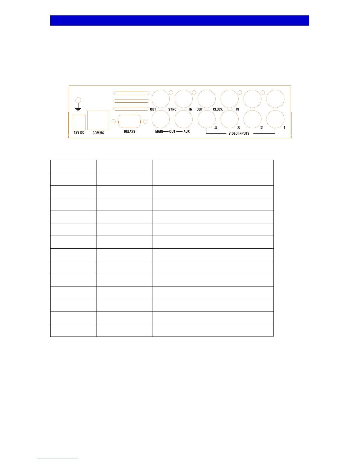
2.2 Rear Panel...........................................................................................................................................3
2.2.1 COMMS Port Pin-out....................................................................................................................4
2.2.2 RELAYS Port Pin-out...................................................................................................................4
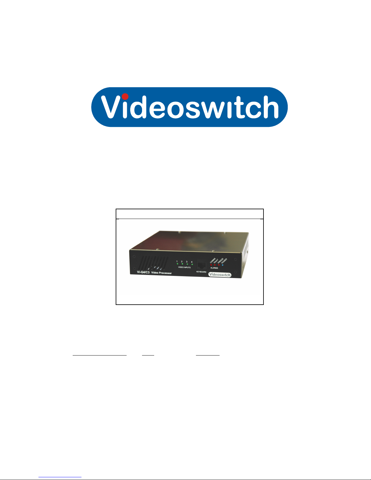
2.3 Front Panel..........................................................................................................................................5
2.3.1 Indicator LEDS.............................................................................................................................5
2.3.2 KEYBOARD Port Pin-out.............................................................................................................6
3 Menus.............................................................................7
3.1 Login 8
3.2 Installer................................................................................................................................................8
3.2.1 PTDI Enable/Disable....................................................................................................................8
3.2.2 Normal Format..............................................................................................................................8
3.2.3 Reversed Format..........................................................................................................................8
3.2.4 Video Loss Mask..........................................................................................................................8
3.3 Display.................................................................................................................................................8
3.3.1 Format..........................................................................................................................................8
3.3.2 Format Title..................................................................................................................................8
3.3.3 Image Metrics...............................................................................................................................8
3.3.4 Title Positions...............................................................................................................................
3.3.5 Selectable Formats......................................................................................................................
3.3.6 Colour Scheme.............................................................................................................................10
3.3.6.1 Text Background...........................................................................................................10
3.3.6.2 Image Borders...............................................................................................................10
3.3.6.3 Background...................................................................................................................10
3.3.6.4 Video Loss.....................................................................................................................10
3.3.7 Titles.............................................................................................................................................10
3.3.7.1 Unit Title........................................................................................................................10
3.3.7.2 Camera1 Title................................................................................................................10
3.3.7.3 Camera2 Title................................................................................................................10
3.3.7.4 Camera3 Title................................................................................................................10
3.3.7.5 Camera4 Title................................................................................................................10
3.3.8 Video Loss Messages..................................................................................................................11
3.3. Luminance Peaking......................................................................................................................11
3.3.10 Automatic Gain Control..............................................................................................................11
3.3.11 Disable On-screen Text..............................................................................................................11
3.3.12 Startup Screen Timeout.............................................................................................................11
3.4 Alarms..................................................................................................................................................11
3.4.1 Video Loss Mask..........................................................................................................................11
3.4.2 Relays Normally On.....................................................................................................................12
3.4.3 Reboot On Error...........................................................................................................................12
3.4.4 Reboot on Freeze.........................................................................................................................12
3.4.5 Max Reboots................................................................................................................................12
3.4.6 Reboot Period...............................................................................................................................12
3.5 Options.................................................................................................................................................12
3.5.1 Anti-Freeze...................................................................................................................................12

3.5.1.1 Freeze Mode.................................................................................................................12
3.5.1.2 Freeze Metrics...............................................................................................................12
3.5.1.3 Freeze White Level.......................................................................................................12
3.5.1.4 Freeze Black Level........................................................................................................12
3.5.1.5 Freeze Threshold..........................................................................................................12
3.5.2 Train Data Interface......................................................................................................................12
3.5.2.1 TDI Line Number...........................................................................................................12
3.5.2.2 TDI Bits/Line..................................................................................................................12
3.5.2.3 TDI Default Data............................................................................................................12
3.5.2.4 TDI White Level.............................................................................................................12
3.5.3 Genlock........................................................................................................................................12
3.5.3.1 Genlock Mode...............................................................................................................12
3.5.3.2 27MHz Clock Offset......................................................................................................12
3.5.3.3 Line Offset.....................................................................................................................12
3.5.3.4 Pixel Offset....................................................................................................................12
3.5.4 Heartbeat Cursor..........................................................................................................................12
3.5.4.1 Enable Cursor...............................................................................................................12
3.5.4.2 Cursor X........................................................................................................................12
3.5.4.3 Cursor Y........................................................................................................................13
3.5.4.4 Flash Period(ms)...........................................................................................................13
3.5.4.5 Cursor Background Colour............................................................................................13
3.5.5 Command Timeout(ms)................................................................................................................13
3.6 Config...................................................................................................................................................14
3.6.1 Address........................................................................................................................................14
3.6.2 Text Size.......................................................................................................................................14
3.6.3 Lock Keypad.................................................................................................................................14
3.6.4 Password......................................................................................................................................14
3.6.4.1 Installer Password.........................................................................................................14
3.6.4.2 Super-user Password....................................................................................................14
3.6.5 Auto Log-out time(secs)...............................................................................................................14
3.6.6 Restore Factory Settings..............................................................................................................14
4 Co and Protocol........................................................15
15
4.1 RS485 Commands..............................................................................................................................16
5 Specifications................................................................19
5.1 Default Screen Formats.......................................................................................................................1
5.2 Video Processing.................................................................................................................................1
5.3 Display.................................................................................................................................................20
5.4 Control and Interface...........................................................................................................................20
5.5 Power, Physical & Environmental........................................................................................................21
5.6 Firmware & Logic Upgrades................................................................................................................21
5.7 Assembly Drawing...............................................................................................................................22

Vi-Q4/C3 User Manual Viq602c
1 Overview
The Vi-Q4C3 is a quad video processor that accepts analogue video from up to four cameras or
other video sources and combines them on a single video output.
Each video input image can contribute to the composite real-time image on the analogue video
output.
The image from each input channel can be individually scaled, cropped, mirrored and positioned.
Menus allow the user to configure the unit
Configuration may also uploaded and downloaded using a PC
The Vi-Q4/C3 has fully user-programmable screen formats
The Vi-Q4/C3 can be gen-locked from another The Vi-Q4/C3
The Vi-Q4/C3 has features specifically aimed at rail transport applications including special
circuitry to monitor performance, alarm relays for reporting error conditions, rugged build standard
for hostile environments.
Video presence is displayed on front-panel LEDs and loss of video can trigger alarm relays (per
channel) if required.
Freeze detection hardware, that is independent of the main video processing path, monitors the
system to ensure frozen or swapped imaged cannot be displayed should a malfunction occur
within the unit.
If polled RS485 communication is used, an alarm is invoked if communication is lost.
Watchdog timers monitor the correct operation of the main processor and other hardware.
Software updates may be installed via either the front-panel or rear-panel RS485 ports.
Videoswitch Ltd 1/26 07/0 /15

Vi-Q4/C3 User Manual Viq602c
2 Connections and Indicators
2.1 Typical Configuration
Videoswitch Ltd 2/26 07/0 /15

Vi-Q4/C3 User Manual Viq602c
2.2 Rear Panel
The rear panel connectors are detailed below and in subsequent pin-out tables:
Identification Connector Type Function
MAIN OUT BNC Multi-screen output
AUX OUT BNC Test output
1 BNC Camera 1 Input
2 BNC Camera 2 Input
3 BNC Camera 3 Input
4 BNC Camera 4 Input
SYNC OUT BNC Composite sync gen-lock output
SYNC IN BNC Composite sync gen-lock input
CLOCK OUT BNC 54MHZ video processor clock gen-lock output
CLOCK IN BNC 54MHZ video processor clock gen-lock input
COMMS RJ45 RS485 port
12V 2.1mm Coax Power 12V DC Power input, 500mA
RELAYS -way Female D-type Alarm relays contacts
Videoswitch Ltd 3/26 07/0 /15

Vi-Q4/C3 User Manual Viq602c
2.2.1 COMMS Port Pin-out
Pin Function
1 RS485 Input+ (A)
2 RS485 Input- (B)
3 RS485 Output+ (A)
4 +12V output for Keyboard
5 GND
6 RS485 Output- (B)
7 Not used
8 Not used
2.2.2 RELAYS Port Pin-out
Pin Function
1 Alarm 1 – Video loss 1
2 Alarm 2 – Video loss 2
3 Alarm 3 – Video loss 3
4 Alarm 4 – Video loss 4
5 GND
6 Alarm 5 - System error alarm
7 Alarm 6 - Comms loss alarm
8 Relay Common
12V Input or output
Videoswitch Ltd 4/26 07/0 /15
54
9
3
8
21
76
PIN1 PIN8

Vi-Q4/C3 User Manual Viq602c
2.3 Front Panel
The Vi-Q4C3 has LEDs on the a front panel with to indicate video status and alarm information. It also has
a RS485 port for configuration and test purposes.
2.3.1 Indicator LEDS
LED Function Colour
1 Video Input 1 present Green
2 Video Input 2 present Green
3 Video Input 3 present Green
4 Video Input 4 present Green
COMMS No commands received via COMMS port within programmed
period
Red
FAULT A system fault has been detected Red
FREEZE Freeze detected one or more camera images Red
POWER 12V power is present Blue
Videoswitch Ltd 5/26 07/0 /15

Vi-Q4/C3 User Manual Viq602c
2.3.2 KEYBOARD Port Pin-out
Pin Function
1 RS485 Input+ (A)
2 RS485 Input- (B)
3 RS485 Output+ (A)
4 +12V output for Keyboard
5 GND
6 RS485 Output- (B)
7 Not used
8 Not used
Videoswitch Ltd 6/26 07/0 /15
PIN1 PIN8

Vi-Q4/C3 User Manual Viq602c
3 Menus
Menus are accessible using a Vi-K1000 keyboard plugged into the CONSOLE or COMMS port. They may
also be accessed using a virtual keyboard included in the configuration manager application, Vi-SA2
Key
na e Key legend Action
MENU Enter the menu system.
Up Select the prior menu item or scroll a value when
editing
Down Select the next menu item or scroll a value when
editing
Right Go a level deeper into the menu or move cursor when
editing
Left Come out of a level in the menu or move cursor when
editing
TAG Set the default setting of a menu item
ESC Escape from a menu level or from editing a value
LIVE Leave menu completely. Any changes will be saved.
Videoswitch Ltd 7/26 07/0 /15

Vi-Q4/C3 User Manual Viq602c
3.1 Login
Some parts of the menu are password protected. Enter the password here to gain access to the menu.
Use left and right to move the cursor
Use up and down to select the digits
Use left or ESC to exit this menu item
A message on the screen will indicate if you have logged in successfully. A timer keeps you logged in while
you are pressing keys. After a period if inactivity, you will be logged out. You may manually log out by
changing the password to an invalid value (e.g. all zeros). The default user password is: 111111.
3.2 Installer
3.2.1 PTDI Enable/Disable
3.2.2 Normal Format
3.2.3 Reversed Format
3.2.4 Video Loss Mask
3.3 Display
3.3.1 Format
Prior to editing image positions of title positions, select the screen format that you wish to edit. If you select
format 0, a colour bar test pattern is displayed.
3.3.2 Format Title
3.3.3 Image Metrics
Use the nu ber keys 1, 2, 3 and 4 to select the camera for which you wish to adjust the image
position.
Use the up and down keys to select which field you wish to edit
Use the left and right keys to edit the number in the selected fields
Use DEFAULT to restore the factory defaults of the selected screen format
Repeat for other cameras
Press ESC to exit this screen back to the menu
The image parameters that can be adjusted are:
Videoswitch Ltd 8/26 07/0 /15

Vi-Q4/C3 User Manual Viq602c
Field X range Y range
Co ents
Visible YES or NO
Determines whether the camera image is
displayed
Top Left 0 to 176 0 to 142
Position of the top-left corner of the
displayed camera image
Bottom Right 0 to 176 0 to 142
Position of the bottom-right corner of the
displayed camera image
Scale 0 to 255 0 to 255
The scale of the displayed image relative
to the input image (255 represents 1:1)
Offset 0 to 176 0 to 142
The position in the input image that
becomes the top-left of the display
image.
Mirror YES or NO YES or NO
Set to YES if you want the image to be
mirrored horizontally, vertically or both.
Note:
The coordinate X=0, Y=0 represents the top-left of the image.
X-coordinates refer to the horizontal, larger numbers being further to the right
Y-coordinates refer to the vertical, larger numbers being further to the bottom
3.3.4 Title Positions
Use the nu ber keys 1, 2, 3 and 4 to select the camera for which you wish to adjust the image
position.
Use the number keys 9 and 0 to select the Date/Ti e and Unit title
Use the up, down, left and right keys to move the selected title to the desired location on the
screen.
Note that the down key moves the title down by 8 steps whilst up moves it up by just 1 step. This
arrangement allows fine control of the vertical position without requiring too many key presses.
Use DEFAULT to restore the factory defaults of the selected screen format
Repeat for other cameras
Press ESC to exit this screen back to the menu
Field X range Y range
Camera Title 0 to 57 0 to 144
Unit Title 0 to 57 0 to 144
Date/Time 0 to 57 0 to 144
The coordinate X=0, Y=0 represents the top-left of the image.
X-coordinates refer to the horizontal, larger numbers being further to the right
Y-coordinates refer to the vertical, larger numbers being further to the bottom
3.3.5 Selectable Formats
Screen formats may be selected from the keypad by pressing the nu ber keys or the left and right keys.
This menu option allows you to specify which formats you want to be able to select.
Videoswitch Ltd /26 07/0 /15

Vi-Q4/C3 User Manual Viq602c
Use left and right to move choose the format
Use up and down to specify whether you want the format to be selectable from the keypad or not.
A solid block indicates a format can be selected whereas a dash indicates that it cannot.
3.3.6 Colour Scheme
3.3.6.1 Text Background
You can choose whether the text is surrounded by a solid block of black or blue background colour or just
a thin border (to ensure the text can be ready whatever the colour of the video image).
3.3.6.2 I age Borders
Each camera image may be surrounded by a black or white border, or no border.
3.3.6.3 Background
3.3.6.4 Video Loss
3.3.7 Titles
3.3.7.1 Unit Title
The Video Processor may be given a unit title that is displayed on the screen at all times.
Use left and right to move the cursor
Use up and down to select the character
Use DEFAULT to default or clear the title
3.3.7.2 Ca era1 Title
Each camera may be given a title that is displayed on the screen whenever that camera image is
displayed.
Use left and right to move the cursor
Use up and down to select the character
Use DEFAULT to default or clear the title
3.3.7.3 Ca era2 Title
See above
3.3.7.4 Ca era3 Title
See above
3.3.7.5 Ca era4 Title
See above
Videoswitch Ltd 10/26 07/0 /15

Vi-Q4/C3 User Manual Viq602c
3.3.8 Video Loss Messages
3.3. Luminance Peaking
3.3.10 Automatic Gain Control
3.3.11 Disable On-screen Text
3.3.12 Startup Screen Timeout
3.4 Alar s
3.4.1 Video Loss Mask
This mask determines which input are monitored for video loss.
Use left and right to move the cursor
Use up and down to select whether the input is to be monitored for video loss. A solid block
indicates that monitoring is ON. A dash indicates that monitoring is OFF.
Use DEFAULT to default the monitoring settings to all on or all off.
Videoswitch Ltd 11/26 07/0 /15

Vi-Q4/C3 User Manual Viq602c
3.4.2 Relays Normally On
3.4.3 Reboot On Error
3.4.4 Reboot on Freeze
3.4.5 Max Reboots
3.4.6 Reboot Period
3.5 Options
3.5.1 Anti-Freeze
3.5.1.1 Freeze Mode
3.5.1.2 Freeze Metrics
3.5.1.3 Freeze White Level
3.5.1.4 Freeze Black Level
3.5.1.5 Freeze Threshold
3.5.2 Train Data Interface
3.5.2.1 TDI Line Nu ber
3.5.2.2 TDI Bits/Line
3.5.2.3 TDI Default Data
3.5.2.4 TDI White Level
3.5.3 Genlock
3.5.3.1 Genlock Mode
3.5.3.2 27MHz Clock Offset
3.5.3.3 Line Offset
3.5.3.4 Pixel Offset
3.5.4 Heartbeat Cursor
3.5.4.1 Enable Cursor
3.5.4.2 Cursor X
Videoswitch Ltd 12/26 07/0 /15

Vi-Q4/C3 User Manual Viq602c
3.5.4.3 Cursor Y
3.5.4.4 Flash Period( s)
3.5.4.5 Cursor Background Colour
3.5.5 Command Timeout(ms)
Videoswitch Ltd 13/26 07/0 /15

Vi-Q4/C3 User Manual Viq602c
3.6 Config
3.6.1 Address
3.6.2 Text Size
3.6.3 Lock Keypad
If you do not want the user to be able to select screen formats or cameras, set this option to YES. To
change screen format you now have to enter menu, enter password and change the screen format in the
For at menu.
3.6.4 Password
3.6.4.1 Installer Password
3.6.4.2 Super-user Password
3.6.5 Auto Log-out time(secs)
3.6.6 Restore Factory Settings
Set this option to Yes if you want to default all settings including screen formats to the factory defaults.
Videoswitch Ltd 14/26 07/0 /15

Vi-Q4/C3 User Manual Viq602c
4 Co and Protocol
Both front and rear RS485 ports are capable of accepting and replying to commands. Replies are only sent
to the port receiving the command.
Character format: 600 baud, 1 start, 2 stop, no parity
Message format:
Start of
message
Source
address
Dest
Address
Extended
Data
Command Parameter End of Message
[ SS DD XX..XX CC PP ]
where
[ start of message (5B)
SS source address
DD Vi-Q4/C3 address (0,1,2,3 etc or FF= broadcast)
XX.XX Extended data, 0 to 128 bytes depending on command
CC Command
PP Parameter
] end of message (5D)
Note that, except for start and end characters, all message content comprises pairs of hex-ascii characters.
Videoswitch Ltd 15/26 07/0 /15

Vi-Q4/C3 User Manual Viq602c
4.1 RS485 Co ands
Key:
VP Vi-Q4/C3 Video Processor
EXT External controller such as PTDI, keyboard, PC
SS Source address byte
DD Destination address byte
XX..XX Extended data bytes (0 to 128 bytes permitted). If representing an ASCII string, two hex numbers
are used to encode each ASCII character within the string (e.g. “0123 ” is coded as 30313233).
CC Command byte
PP Parameter byte
0xNN Hex number
Co and
Na e
Co and
Originator
CC PP Description
Poll EXT 0xBB 0x00
to
0xFF
This command should be send to the Video Processor (VP)
regularly to hold off the COMMS alarm. The PP value must
change (e.g. increment) each time the command is issued
Ack VP 0xBA 0x00
to
0xFF
This command is send by the VP to acknowledge other
commands. The source address is VP address, DD is a copy
of the original command's source address,SS. This value can
be used to identify the command instead of being a fixed
source number. PP is the module 256 sum of all bytes in the
original command.
Set screen
format
EXT 0x10 0x11
0x17
0x80
to
0xA0
Set displayed screen format to previous number
Set displayed screen format to next number
Set displayed screen format to 0 to 32
Request
configuration
EXT 0x43 0x02 This command will cause the VP to send its whole
configuration as a series of Configuration Item commands
Configuration
Item
VP 0x42 0x02 The extended data XX..XX in this reply command contains an
ASCII string representing a menu configuration item and its
value e.g. “Format=5”
Save
configuration
EXT 0x42 0xE1 This commands causes the VP to save the entire
configuration to non-volatile memory. The memory has a
limited life-time of 1 Million write cycles (minimum), so this
command should not be issued too frequently.
Log-in EXT 0x46 0x00 The password represented as an ASCII string is passed as
extended data, XX..XX. If a valid password is received, this
enables subsequent access to the menu system.
Request Serial
Number
EXT 0x43 0x51 Issuing this command to the VP results in a Serial Number
reply command
Serial Number VP 0x44 0x51 This reply command from the VP includes the serial number
Videoswitch Ltd 16/26 07/0 /15
Table of contents
Other Videoswitch Media Converter manuals