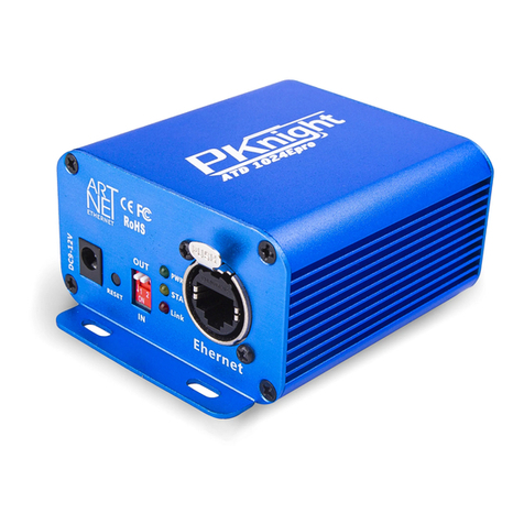
Pknight CR021R User manual

1/12
CR021R
(Art-Net-DMX512 Network Converter)
Ver1.0
CE

2/12
=================================== CONTENTS=================================
1. Parameters...........................................................................................................3
2. Panel Introduction............................................................................................... 4
3.Introduction of the lower side plate...................................................................5
4.Introduction of upper plate(Installation 1)........................................................5
5. Introduction of both side(Installation 2)...........................................................6
6. Configuring System Parameters..........................................................................6
Table 1 - Button instruction..........................................................................................................................................6
Table 2 - The steps for setting the parameters...........................................................................................................6
Table 3 - The menu presentation for output mode(the form contents to factory default values).....................7
Table 4 - Sets the error information table...................................................................................................................7
Table 5 - Recommended network settings:................................................................................................................ 7
Table 6 - Art-Net Network working conditions.............................................................................................................7
Table 7 -Port addresses definition...............................................................................................................................8
Table 8 -Attention about setting parameters..............................................................................................................8
7.Application 1:LED matrix screen driver.............................................................9
8.Application 2:The control lighting system from the Art-Net port to control the
Dmx 512 lighting equipment...................................................................................9

3/12
Introduction
CR021R is standard Art-Net Node. Because of this, you can use the device
with any application, console, or controller that supports Art-Net to
distribute Art-Net data via Ethernet network. Commonly the CR021R can be
used to extend the DMX output ports of tiger touch and MA2.
1. Parameters
Type
Parameters
Modify
yes/not
Configuration methods
Art-Net Equipment Name
CR021R
DMXWorkShop
Default IP Address
10.201.6.100
LCD Menu
Art-Net Broadcast Address
10.255.255.255
LCD Menu
Subnet Mask
255.0.0.0
LCD Menu
MAC address
d-4d-48-c9-06-64
LCD Menu
Support Art-Net Protocol
Art-Net I, Art-Net II, Art-Net
III
DMX512 Port Address
Net: 0, Subnet: 0,
Universe: 0-15
LCD Menu
NIC Speed
100Mbps
DMX512 output
2 universe
DMX512 Channels
2 x 512
LED(R-G-B)Pixels
2x 170
Power Supply 1
AC90-240V/50-60Hz
Power Supply 2
International POE,DC48V
DMXWorkShop
PC Software

4/12
2. Panel Introduction
10
7
6 9
8
5
4
3
1 2
NO.
Type
Function
1
Power Indicator: White LED
Show the power connection state
2
DMX512 signal indicator: Blue LED
DMX512 data running state
3
Art-Net data running indicator: White LED
data running state
4
Art-Net Connector Indicator: White LED
Physical link state
5
Menu button
Into set up state and set up selection
6
Up button
Parameter input
7
Down button
Parameter input
8
Enter button
Parameter change(short press) and
save(long press)
9
LCD display
Through the LCD menus to manually set
the system parameters, If LCD backlight
has not button operation, automatic shut
down after 5 minutes.
10
2pcs 3-XLR
Output DMX 512 signal

5/12
3.Introduction of the lower side plate
1 2
Number
Type
Function
1
AC220V Power Supply
Socket
AC90-240V/50-60Hz
2
Internet RJ45 port
Art-Net input,
International POE, 48V input
4.Introduction of upper plate(Installation 1)
Hook mounting holes(M10Screw hole) The effect of hook installation

6/12
5. Introduction of both side(Installation 2)
screw mounting holes on both sides, which can be fixed with screws
6. Configuring System Parameters
Table 1 - Button instruction
Key
Function
Menu (cancel)
UP
Down
Enter
(save)
Table 2 - The steps for setting the parameters
The buttons operation steps for setting each Art-Net parameter, as follows:
steps
instruction
1
Press the [MENU] to choose and switch the parameter menu;
2
Press the [ENTER] to edit the parameter menu,(then Appears blinking cursor)
3
Press the [ENTER], can switch the specific parameter (the parameter at the blinking cursor was
the one already choose)
4
Press [UP] or [DOWN],can modify the current parameters; Long press [UP]or [DOWN] for 1S to
quickly modify the current parameters
5
Long press the[ENTER] for more than 1S,system will save the modified parameters . If the info
was wrong, it will not be saved, then press [ENTER] to clear the wrong info, also can enter the
values follow the presentation and save again.

7/12
Table 3 - The menu presentation for output mode(the
form contents to factory default values)
Menu
DMX output mode
Default values
1
IP address
<Local IP >
10.201.6.100
2
Subnet Mask
<Subnet Mask>
255. 000. 000.000
3
Output Port universe
<Port universe>
OUT01~OUT02
00-01
4
Output Port net
< Port Net>
Net: 000
5
Output Port subnet
< Port Sub-Net>
SubNet: 00
6
Ethernet MAC
<Ethernet MAC>
d-4d-48-c9-06-64
7
Default Set
<Default Set>
No(Yes)
Table 4 - Sets the error information table
Menu item
LCD display the error info
The instruction for the error info
Set the local IP &
subnet mask
!!Local IP: hosted can’t is 0!!
Local IP host number is not 0
! Local IP hosted can’t all is 1!
Local IP host number is not 1
Set the input route
!!Port Universe can’t be same!!
The different DMX input ports must be only
Set the transmit
mode
"!!NO AD4 KEY!!"
Didn't get to the correct encryption information
Table 5 - Recommended network settings:
IP Address
Subnet Mask
Broadcast Address
2.x.x.x
255.0.0.0
2.255.255.255
10.x.x.x
255.0.0.0
10. 255.255.255
192.168.x.x
255.255.255.0
192.168.x.255
Table 6 - Art-Net Network working conditions
1
Network devices have the same subnet mask
255.x.x.x
2
Network devices have the same network segment and
unique IP address
2.x.x.x
10.x.x.x
192.168.x.x
3
Correct port address: Net+Sub-Net+Universe
000 + 00 + (0…15)
4
Network device has a unique MAC address
d-4d-48-c9-06-64
5
Network equipment is used with crossed cable, router,
switchboard, and connect multiple network devices
crossed cable, router

8/12
Table 7 -Port addresses definition
Port addresses
Net
Subnet
Line
Port Address
Net (0-127)
Subnet (0-15)
Universe (0-15)
Table 8 -Attention about setting parameters
NO.
Menu item
Pay attention to the items
1
Setting IP address
Each network set must have a unique IP address (not Other network
equipment occupancy) and the same subnet mask, otherwise will
cause the network does not work.
2
Setting subnet mask
The subnet mask is 255.x.y.z, do not need to modify x, y, z one by one,
we provide the subnet mask from menu table, there are 23 subnet
mask which may be used, select the subnet mask that you want to set
code on it.
3
Setting port of subnet
address
Each network (Net) of Art-Net includes 16 (universe)
The range is 0-15.
4
Setting port of
network address
Each network (Net) of Art-Net includes 256 route (universe),
Settings range from 0-127,
5
Setting the NIC's
MAC address
Each network device have a network card, each card must have
Unique MAC address d-00-22-a8-00-64, and the last 3 values of this
card’s MAC address already have been binding with the last 3 values
of IP address, can effectively prevent the collision about the MAC
address. If there is NIC conflict, the user can modify the second, the
third bytes of the MAC address.
6
default set
CR051R support default set, If you want to reset, all the parameters
which have been kept before, will modify the original parameters,
include the transmission mode , input mode also will be converted to
output mode, and the network parameter, Port addresses will be
initialized to default values.

9/12
7.Application 1:LED matrix screen driver
Equipment
Function
PC computer
Running Jinx!-LED Matrix Control
CR041R internet converter
Convert the Art-Net to 2ways DMX 512
Dmx512 Decoder(LED Decoder)
Convert the DMX512 to the signal of RGB LED strip
RGB LED trip(Assemble to the Matrix screen)
300pcs dot ,R,G,B ,3 channels
Size of the Matrix
20 x 17
Switch power
(support power to the RGB LED trip)
5V - 40A -200W
Equipment connection blocks diagrams:
8.Application 2:The control lighting system from the
Art-Net port to control the Dmx 512 lighting equipment
Equipment
Function
Art-Net lighting controller equipment
Running Jinx!-LED Matrix Control
CR021R internet converter
Convert the Art-Net to 2 ways DMX 512
Dmx512 lighting equipment
Receive the DMX512 signal to show the lighting effect
PC computer
CR021R
(Art-Net----DMX512)
LED
decoder 1
LED
decoder 2
LED stripe 1
LED stripe 2

10 /12
Equipment connection blocks diagrams:
Console
Switch/Router
Universe1
Universe2
CR021R(Art-net converter)

11 /12

12 /12
Table of contents
Other Pknight Media Converter manuals
Popular Media Converter manuals by other brands

Imagenation
Imagenation PXD1000 quick start guide

Axis
Axis P7224 user manual

Transition Networks
Transition Networks E-100BTX-FX-N-02 user guide

DEVA Broadcast
DEVA Broadcast DB9009-RX Maintenance and operation instruction manual

Blake UK
Blake UK Proception PROHDMISP12IR manual

Gefen
Gefen EXT-DVI-2-VGAN user manual