Videoswitch Vi-POSCON User manual

Videoswitch 1 Pos601a.doc
Vi-POSCON Installation Guide
Vi-POSCON
Installation Guide
Document Reference Date
Pos601a.doc 20/03/2007
Videoswitch Telephone 01252-851510
Ocean House, Redfields Industrial Park Fax 01252-851296
Hants GU52 0RD Web www.videoswitch.co.uk

Videoswitch 2 Pos601a.doc
Vi-POSCON Installation Guide

Videoswitch 3 Pos601a.doc
Vi-POSCON Installation Guide
Contents
1CAUTIONS ............................................................................................................................ 5
2About this Guide .................................................................................................................... 5
2.1 If you need assistance, call…......................................................................................... 5
3Introduction............................................................................................................................ 6
4System Components.............................................................................................................. 7
4.1 Vi-POSCON Front Panel ................................................................................................ 9
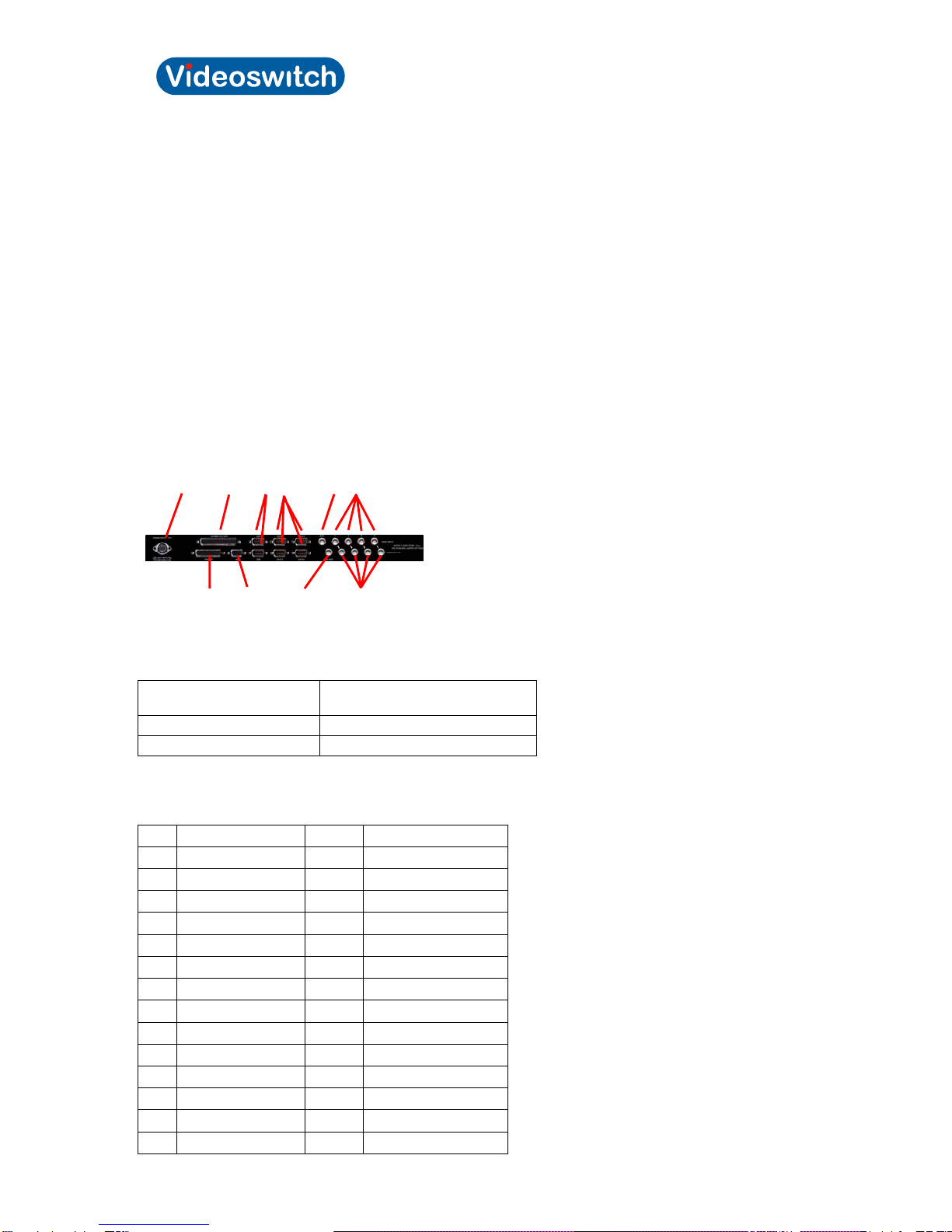
4.2 Vi-POSCON Rear Panel................................................................................................. 9
4.3 The Vi-POSCON Text Overlay ..................................................................................... 11
5Installation............................................................................................................................ 12
5.1 Introduction................................................................................................................... 12
5.2 Before You Begin.......................................................................................................... 12
5.3 Pre-Installation Checklist .............................................................................................. 12
5.4 Controller Installation Kits and Tools ............................................................................ 13
5.4.1 Install Kits................................................................................................................ 13
Installation Tools.................................................................................................................. 13
5.5 Installing a Vi-POSCON System................................................................................... 14
5.6 Power-Up Sequence..................................................................................................... 18
6Configuring the Vi-POSCON System................................................................................... 19
7The Vi-POSCON Service Menu........................................................................................... 20
7.1 Accessing the Service Menu......................................................................................... 20
7.2 Setting the Active Channels.......................................................................................... 21
7.3 Setting the Language.................................................................................................... 21
7.4 Setting the Currency Format......................................................................................... 22
7.5 Setting the Printer Type................................................................................................ 22
7.6 Displaying the Software Version................................................................................... 22
7.7 Setting the Unit Status.................................................................................................. 22
7.8 Setting Synchronize Clock............................................................................................ 23
7.9 Setting/Activating Alarm Events.................................................................................... 23
7.9.1 Setting the Current Alarm........................................................................................ 23
7.9.2 Setting the Identifier................................................................................................. 24
7.9.3 Setting the Alarm Allocation .................................................................................... 24
7.9.4 Setting the Contact Type......................................................................................... 24
7.9.5 Setting the Alarm Status.......................................................................................... 25
7.9.6 Setting the Alarm Duration ...................................................................................... 25
7.9.7 Setting the Active Period......................................................................................... 25
7.9.8 Setting the Start Time.............................................................................................. 25
7.9.9 Setting the End Time............................................................................................... 26
7.10 Setting the Channel Attributes...................................................................................... 26
7.10.1 Setting the Current Channel.................................................................................... 26
7.10.2 Setting the Baud Rate ............................................................................................. 26
7.10.3 Setting the Line Filtering.......................................................................................... 28
7.10.4 Setting the Register Identity .................................................................................... 28
7.10.5 Setting the Text Colour............................................................................................ 28
7.10.6 Setting the Text Window Border.............................................................................. 28
7.10.7 Setting the Text Window Position............................................................................ 29
7.10.8 Setting the Text Window Size.................................................................................. 29
7.11 Setting the Screen Attributes ........................................................................................ 29
7.11.1 Displaying Channel Bar........................................................................................... 29
Displaying Date & Time ....................................................................................................... 30
7.11.2 Setting the Video Type............................................................................................ 30
7.12 Clearing the User Password......................................................................................... 30
7.13 Print System Settings.................................................................................................... 30
7.14 Manager Menu.............................................................................................................. 30
7.15 Event Reports............................................................................................................... 31
8Troubleshooting................................................................................................................... 32
8.1.1 No Cash Transactions on Monitor........................................................................... 32
8.1.2 No Vi-POSCON Identifying Message on Monitor .................................................... 34
8.1.3 Menus Absent or Distorted on Monitor.................................................................... 36
8.1.4 No Video on Monitor................................................................................................ 36
8.1.5 No Mouse Function ................................................................................................. 36
8.1.6 No Printer Function.................................................................................................. 37
9Specifications....................................................................................................................... 39
9.1 Electrical....................................................................................................................... 39
9.2 Mechanical.................................................................................................................... 39
9.3 Environmental............................................................................................................... 39
10 Declarations......................................................................................................................... 40

Videoswitch 4 Pos601a.doc
Vi-POSCON Installation Guide
10.1 Regulatory Compliance................................................................................................. 40
10.2 Other Declarations........................................................................................................ 40

Videoswitch 5 Pos601a.doc
Vi-POSCON Installation Guide
1 CAUTIONS
CAUTION: For continued protection against risk of fire, replace only with the same type and rating of
fuse.
PCB Legend Value Type
Fuse F1 1A @ 250V Ceramic "F"
Fuse F2 500mA @ 250V Ceramic "L"
Fuse F3 500mA @ 250V Ceramic "L"
CAUTION: Danger if battery is incorrectly replaced.
Replace only with the same or equivalent type recommended by the manufacturer. Dispose of
batteries according to the manufacturer's instructions.
IMPORTANT!
PLEASE READ CAREFULLY
PURCHASERS WHO INSTALL THIS DEVICE FOR USE BY OTHERS MUST NOT
LEAVE THIS DOCUMENT WITH THE CUSTOMER.
PRECAUTIONS: Check that the operating voltage as indicated on the type plate [label] of the Power
Supply Unit [PSU] is identical with the voltage of your local mains power supply.
LOCATION: For pluggable equipment [which is the PSU], the socket outlet shall be installed near the
equipment, [the PSU], and shall be easily accessible.
Do not expose the Vi-POSCON or the PSU to humidity, rain or excessive heat; they are for use in dry
areas only.
SAFETY: The Mains Plug is considered to be the means of disconnecting primary power. To isolate
the equipment fully, ensure that the Mains Plug is removed.
All Video, Data and Alarm switching signal connections must be to SELV* levels only, in accordance
with EN 6095 and UL 1950 3rd Edition.
INSTALLATION: Both the Vi-POSCON and the PSU are designed to be free standing on a horizontal
surface.
NOTES:
*SELV = Safety Extra Low Voltage.
PSU = Power Supply Unit.
A separate copy of this safety card is included with the Vi-POSCON Install Kit and must be left with
the user.
2 About this Guide
This document describes the installation and configuration of the Vi-POSCON System.
2.1 If you need assistance, call…
Videoswitch: 01252-851510

Videoswitch 6 Pos601a.doc
Vi-POSCON Installation Guide
3 Introduction
The Vi-POSCON System is a point-of-sale exception monitoring device that connects to a store's
cash registers and camera surveillance system.
The Vi-POSCON System monitors EPoS (Electronic Point-of-Sale or cash register) terminal activity
and documents suspicious sales transactions. It does this by monitoring the register data for up to 10
sales transactions that the operator has designated as exception events. It also monitors up to four
external switch events (such as door switch or panic button).
When an exception event occurs, Vi-POSCON documents the event by:
Switching the DVR from time-lapse to real-time recording to record the register scene.
Displaying the register scene on a video monitor in a back room or office.
Highlighting the exception on the register receipt that overlays the video scene.
Generating a one-line printout that summarizes the exception event (if the Audit Trail option is
enabled).
Storing exception event information for the system reports.
By sounding an alarm tone.
Changes the relevant front panel Data LED from flashing green to steady red for the duration of the
event.
By lighting the red EVENT LED when the first event is logged. (The LED is not cleared until the event
is reviewed.)
After the system documents an exception, it:
Returns to routine surveillance, monitoring the register data according the surveillance parameters
you defined.
Switches the DVR from real-time to time-lapse recording.
Changes the relevant front panel Data LED from steady red to flashing green.
The Vi-POSCON System stores exception event data in its memory for generating its reports. The
Detailed Event Report provides complete details of the exception events. The Frequency Event
Report totals the number of exception events occurring per hour accumulatively over a number of
days. The Daily Report totals the number of exception events occurring per hour for a single day, for
up to 7 days. You can display and print the reports.

Videoswitch 7 Pos601a.doc
Vi-POSCON Installation Guide
4 System Components
The following illustration shows the components of a typical Vi-POSCON System for a single register
installation. Vi-POSCON can monitor up to four cash registers with a single DVR and video monitor.
Depending upon the specific needs of each installation, the system setup will vary from site to site.
The Vi-POSCON components required for a single cash register installation are described below. The
printer is optional, but is typically included.
Camera Provides video of the register scene or, if using a programmable
dome, other locations in the store.
Cash register The EPoS or electronic cash register system used to execute sales
related transactions. In this guide, the term register is used
interchangeably with EPoS.
Monitor Displays the live register scene, an overlay of the register receipt on
the register scene, and Vi-POSCON menus.
Mouse A pointing device used to control and program the Vi-POSCON
System.
Printer
(optional)
Prints a record of exception events as they occur, and prints
summary event reports.
Vi-POSCON Controller Controls the Vi-POSCON System for up to four registers and
cameras, including the switching of a time-lapse DVR.
It can also control the monitoring of up to four external switch events
(alarms), such as door switch or panic button.
Printer Port Interface (PPI) Connects a register to the Vi-POSCON controller; it converts the
register data into Vi-POSCON-understandable data.
DVR Records (in time-lapse mode) the register scene. When an exception
occurs, the DVR records (in real-time mode) the register scene along
with an overlay of the register receipt.

Videoswitch 8 Pos601a.doc
Vi-POSCON Installation Guide
The following illustration shows the maximum Vi-POSCON System configuration with one DVR and
monitor. You can connect up to four registers, cameras, DVRs, and monitors to the Vi-POSCON
controller. A Printer Interface is required for each register you want to monitor.
Vi-POSCON
Controller
Printer
(optional)
VCR or DVR Mouse
Video
Monitor
EPoS & Printer
Interface
EPoS & Printer
Interface
EPoS & Printer
Interface
EPoS & Printer
Interface
Camera 1
Camera 2
Camera 3
Camera 4

Videoswitch 9 Pos601a.doc
Vi-POSCON Installation Guide
4.1 Vi-POSCON Front Panel
The following is a escription of the Vi-POSCON front panel indicators and connector.
POWER – This red LED, when lit, indicates that the unit is powered on.
DATA – These four tri-colour LEDs are linked to the four data input ports on the rear panel. These
LEDs flash green as data is received at the associated interface input; they turn steady red as and
when an event occurs, reverting to flashing green once the period of time defined for the event has
lapsed. If no data is being received at a particular port then the associated LED is not lit.
EVENT – This red LED lights when the first event is logged into Vi-POSCON memory and remains lit
until the user has reviewed that event and all other subsequent logged events.
On system power-up, the DATA and EVENT LEDs momentarily light red.
MOUSE – This is a mini-DIN socket for connecting a PS/2 mouse to the Vi-POSCON System. A tick-
mark indicates the location of the connector's key.
4.2 Vi-POSCON Rear Panel
The following is an illustration and description of the Vi-POSCON rear panel connectors.
[A] Power Input – a DIN connector for the power supply unit (PSU). The following table identifies the
power supplies to be used with the Vi-POSCON Systems.
For Vi-POSCON Systems
in: Use Power Supply Part
Number:
North America 590001
Europe 590002
[B] Alarms I/O & VCR/DVR – a 37-pin D-type female connector for alarm inputs, relay outputs, and
DVR.
Pin Assignment Pin Assignment
1 Relay 1 NO* 20 Relay 1 COM
2 Relay 1 NC* 21 unassigned
3 Relay 2 NO 22 Relay 2 COM
4 Relay 2 NC 23 unassigned
5 Relay 3 NO 24 Relay 3 COM
6 Relay 3 NC 25 unassigned
7 Relay 4 NO 26 Relay 4 COM
8 Relay 4 NC 27 unassigned
9 Relay 5 NO 28 Relay 5 COM
10 Relay 5 NC 29 unassigned
11 unassigned 30 unassigned
12 unassigned 31 unassigned
13 unassigned 32 unassigned
14 unassigned 33 unassigned
[A] [B] [E] [F] [G] [I]
[C] [D] [H] [J]

Videoswitch 10 Pos601a.doc
Vi-POSCON Installation Guide
15 unassigned 34 Alarm GND
16 Alarm Input 4 35 Alarm GND
17 Alarm Input 3 36 Alarm GND
18 Alarm Input 2 37 Alarm GND
19 Alarm Input 1
* NO = Normally Open; NC = Normally Closed
Relay 1 is associated with Channel 1, Relay 2 with Channel 2, Relay 3 with Channel 3, and Relay 4
with Channel 4.
Relay 5 is associated with the Main Monitor output and if Vi-POSCON is configured as a standalone
system, this relay should be connected to the Alarm Input of the time-lapse DVR.
Pin Assignment Connect to DVR
9 Relay 5 NO Alarm SET
10 Relay 5 NC Alarm RESET
28 Relay 5 COM Alarm GROUND
[C] Printer – a 25-pin D-type female connector for connecting the Vi-POSCON printer.
[D] 485 – a 9-pin D-type RS-232/RS485 female connector for future use (to allow the connection of
multiple Vi-POSCON controllers).
[E] 232A and 232B – two 9-pin D-type RS-232 male connectors.
232A is used to output the Synchronizing Clock data to other equipment.
232B is for future use.
The RS-232 output is fixed at 9600, N, 8, 1.
[F] Data1 through Data4 – four 9-pin D-type RS-232/RS-485 male connectors for input from the
Printer Port Interfaces. (The Printer Port Interfaces can output data in either RS-232 or RS-485.)
Wire
Colour RS-232
Data In
Pin
Wire
Colour RS-485
Data In
Pin
RED 2 – RXD 4 – RX+
BLACK 5 – GND 5 – GND
9 – RX-
Note: Jumpers on the Vi-POSCON main PCB must be set to allow RS-232 or RS-485 data input. RS-
232 is the default setting for all four interface data input channels. Interface data input channels may
be set in any combination of RS-232 or RS-485 input.
RS-232/RS-485 Interface Data Input
Data
Input
Channel
Jumper RS-232 Data Input RS-485 Data Input
1 P12
2 P11
3 P10
4 P9
For RS-232, set
jumper towards rear
of unit (default).
For RS-485, set jumper
towards front of unit.
[G] AUX – a BNC connector for future use.
[H] Main Mon. – a BNC connector for the main monitor when Vi-POSCON is configured as a
standalone system (more than one camera/register input with output to a single DVR/monitor).
[I] Video Input (1 through 4) – four BNC connectors for camera input.

Videoswitch 11 Pos601a.doc
Vi-POSCON Installation Guide
Video Input Jumper Notes
1 JP5
2 JP4
3 JP3
4 JP2
AUX JP1
For future use
[J] Video Output (1 through 4) – four BNC connectors for video output. The video output signals
include the text overlay from the EPoS.
4.3 The Vi-POSCON Text Overlay
The monitor text overlay of the Vi-POSCON System is similar to the following illustration. The
surveillance scene is omitted for clarity.
The 3-part text line at the top of the monitor screen displays:
The time in either 12-hour or 24-hour format,
Up to 20 characters for the store's identifier, and
The date in DD/MM/YY, MM/DD/YY, or YY/MM/DD format. (Note: the system replaces the date
separator "/" with "." for the German, Polish, Finnish, Hungarian, Czechoslovakian and Russian
languages, and "-" for the Portuguese and Danish languages.)
The Transaction window displays all register transactions as they occur. The window displays a
maximum of 40 characters per line (38 characters if an outline border is selected). A 12-character
register name box is displayed at the top of the Transaction window.
In the Surveillance Mode, the Channel Bar at the bottom of the screen displays numbered boxes to
indicate the activated video input channels. The example in the above figure shows three activated
channels with Channel 3 being monitored (highlighted). When an event occurs, the system switches
to the channel reporting the event, and its box highlights.
When an Alarm (External) event occurs, the Store Identifier is replaced by a highlighted, flashing
ALARM # (where # = the number of the Alarm) or the Alarm Identifier text (if entered, for example:
DOOR). At the end of the event duration, the Store Identifier is restored.
HH:MM:SS Store Identifier DD/MM/YY
Orange Juice 0.89
Whole Milk 1.23
Skimmed Milk 1.18
Baked Beans 0.26
4 Items 3.56
Tax 0.21
Total 3.77
Cash 5.00
Change 1.23
Register 3
1
2
3
Transaction
window
Channel Bar

Videoswitch 12 Pos601a.doc
Vi-POSCON Installation Guide
5 Installation
5.1 Introduction
This section describes how to install and configure a single controller Vi-POSCON System.
5.2 Before You Begin
Verify that all the equipment has arrived.
Verify that the unit shipped is the right configuration for the store.
Be organized. Unpack components in the back room. At the installation area, lay out parts in the order
you will need them. Do not clutter traffic areas or cause a safety hazard.
5.3 Pre-Installation Checklist
5.3.1.1.1 Salesperson's Responsibilities
Key contacts identified.
Special installation dated noted (verify with Customer Engineer).
Electronic cash register types and printers are identified.
5.3.1.1.2 Customer's Responsibilities
Unswitched, 120Vac or 240Vac, 15A power provided at designated locations to supply the printer
interface(s) and operator station equipment-controller(s), monitor, printer, DVR, and quad splitter, if
installed.
A person with technical knowledge of the electronic cash register system scheduled to support the Vi-
POSCON installation.
5.3.1.1.3 Customer Engineer Responsibilities
Register types noted.
With agreement of the customer, location of the Vi-POSCON station and other components
determined; see Placement below.
Cabling distances between registers and all Vi-POSCON components. A printer interface and data
cable is required for each cash register to be monitored.
5.3.1.1.4 Placement
Vi-POSCON controller location determined, within 2.5m (8') of camera system card rack (if used) for
cable connections.
Printer interface location at registers determined, within 0.9m (3') of AC receptacle.
Four-conductor data cable run from each printer interface to the Vi-POSCON controller.
5.3.1.1.5 AC Power
Three receptacles of unswitched 120Vac or 240Vac, 15A power for the monitor, printer, and DVR. A
fourth receptacle is required if a quad splitter is used.
One receptacle of unswitched 120Vac or 240Vac, 15A power for each Vi-POSCON controller.
One receptacle of unswitched 120Vac or 240Vac, 15A power for each printer interface.
Less than 0.5Vac between neutral and ground of all AC receptacles.

Videoswitch 13 Pos601a.doc
Vi-POSCON Installation Guide
5.4 Controller Installation Kits and Tools
5.4.1 Install Kits
Vi-POSCON Install Kit (US) 540012
Part Number Description Qty
590001 USA PSU 1
520079 37-way D Plug (Solder Bucket) 1
520078 37-way D Cover 1
520075 9-way D Socket (Crimp) 4
520030 9-way D Cover 4
520076 Crimp Pin 12
Vi-POSCON Install Kit (EU) 540013
Part
Number Description Qty
590002 EUR PSU 1
500261 UK Power Cord 1
500262 EUR Power Cord 1
520079 37-way D Plug (Solder Bucket) 1
520078 37-way D Cover 1
520029 9-way D Socket (Solder Bucket) 4
520030 9-way D Cover 4
Accessories
Part
Number Description Qty
590003 Mouse 1
590004 Mouse Mat 1
NOTE: Any replacement or alternative mouse used with the Vi-POSCON system must be UL
approved.
Installation Tools
You will need the following tools to properly install Vi-POSCON:
Crimp tool, D-sub (for Crimp Pin Part #: 520076)
Extractor, D-sub (for Crimp Pin Part #: 520076)
Multimeter or equivalent
Wire stripper/crimper
Soldering iron
Measuring tape
Drill, bits, and screws as needed for mounting (typically to wood)
Drill, bits, and saw as needed for cable routing (typically through wood)

Videoswitch 14 Pos601a.doc
Vi-POSCON Installation Guide
5.5 Installing a Vi-POSCON System
Before installing the Vi-POSCON controller, conduct a site survey with the customer and a
salesperson. For more information on the site survey, see the Pre-Installation Checklist (page 6).
Determine where to install the controller, then continue with the following installation instructions.
Note: Before installing the Vi-POSCON controller, review the system connection diagram in Figures 2
and 3.
Verify pre-installation work.
•Ensure there is adequate space to install the Vi-POSCON controller.
Ensure the power transformer's cables can be routed safely to the controller and to the AC outlet.
Ensure AC power is within 1.8m (6') of the power transformer. The circuit must not be shared with
computer equipment.
Check printer interface-to-Vi-POSCON data cable.
Ensure data cable has been run from the printer interface through an electrical raceway (conduit or duct) to
the Vi-POSCON controller.
Configure the controller for RS-232 or RS-485 operation. The default setting is RS-232.
Remove the controller cover by removing the screws on the top and sides of the unit
Use Jumpers P9 through P12 (Figure 1, page 9) to set the communications protocol according to the
following table:
Data
Channel
Jumper RS-232
(default)
RS-485
1 P12 Pins 1 & 2 Pins 2 & 3
2 P11 Pins 1 & 2 Pins 2 & 3
3 P10 Pins 1 & 2 Pins 2 & 3
4 P9 Pins 1 & 2 Pins 2 & 3
Replace the cover and tighten the screws.
Install the controller.
Based on the site survey guidelines, set the controller in place.
If the controller requires mounting hardware:
Set the controller on the assigned rack shelf and secure it (all rear-panel connectors must be
easily accessible and the red POWER LED should be visible during normal operation).
If the controller does not require mounting hardware:
Set the controller on a shelf or countertop where there is adequate room for cable runs and connections.
Connect the video cables (Figure 2, page 10 or Figure 3, page 11).
Connect a cable from VIDEO OUTPUT 1 (if only one camera) or Main Mon (for multiple camera) on
the controller to the DVR (VIDEO IN).
Connect a cable from the VIDEO OUT connector on the DVR to the monitor (VIDEO IN).
Set the monitor's impedance switch to the 75-ohm position.
Connect a cable from the fixed camera(s) to the controller connector (VIDEO INPUT 1 through 4).
Connect the mouse cable to the MOUSE connector on the front panel of the controller.
Assemble and connect the PPI-to-controller data cable(s) (Figure 2 or 3).
Connect the data cable from the PPI(s) to controller connector(s) (DATA 1 through DATA 4).
Lightly tighten the connector screws to hold the cable(s) in place.
Connect the printer cable (Figure 2 or 3).
Connect the 25-pin connector on printer cable 500252 to the PRINTER connector on the controller.
Lightly tighten the connector screws to hold the cable in place.
Connect the 36-pin Centronics connector on the printer cable to the printer, and fasten the retaining
wires to the connector to hold the cable in place.

Videoswitch 15 Pos601a.doc
Vi-POSCON Installation Guide
Note: If you are installing the 40-column dot-matrix Epson TM-U200D printer option, you must set the
4-position DIP switch located beneath the inspection plate on the bottom of the printer. Set the switch
to the following positions: 1=OFF, 2=OFF, 3=OFF, and 4=ON.
Note: If you are installing the 40-column Epson TM-T88 Thermal printer option, you must set the 8-
position DIP switches located beneath the inspection plate on the bottom of the printer. Set switch
DSW1 to the following positions: 1-6 and 8=OFF, and 7=ON (default). Set switch DSW2 to the
following positions: 1-8=OFF (default).
Note: There are no changeable option settings for the 80-column Epson LX-300 printer. However,
you can use the control panel on the 80-column Epson LX-300+ printer to change its default settings
(refer to the LX-300+ User's Guide for instructions). You may have to change the default paper length;
all other options can remain at their default settings.
For instructions on alarm connections, see the documentation supplied for the DVR.
For instructions on programming the DVR, see the documentation supplied with the unit.
You have completed the Vi-POSCON hardware installation. Continue with the section titled Power-
Up Sequence (page 14).

Videoswitch 16 Pos601a.doc
Vi-POSCON Installation Guide
Figure 1. Controller PCB
CAUTION: Replace fuses only with the same type and rating.
PCB
Legend Value Type
Fuse F1 1A @ 250V Ceramic "F"
Fuse F2 500mA @ 250V Ceramic "L"
Fuse F3 500mA @ 250V Ceramic "L"
P11
P12
P10
P9
1 1
P12
P11
1 1
2 2
3 3
JP2 JP3 JP4 JP5 JP1
R25 R51 R77 R103
C5
U48 U47 U39
BT1
U36
F1 F2
F3
P7
U1
U2
U3
U37
P8 P5
Jumper position for
RS-485 operation Jumper position for
RS-232 operation

Videoswitch 17 Pos601a.doc
Vi-POSCON Installation Guide
Figure 2. System Connection Diagram with four registers

Videoswitch 18 Pos601a.doc
Vi-POSCON Installation Guide
5.6 Power-Up Sequence
This section describes the steps for applying power to the Vi-POSCON System.
CAUTION: Do not apply power to the Vi-POSCON controller or to the printer interface until directed to
do so.
Plug the power cord of the following components (as applicable) into an AC outlet and turn on their
power switch:
Cash registers
Monitor
DVR
Cameras
Verify that these components are powered-on.
Plug the printer's power cord into an AC outlet, and verify that the printer's power LED is lit.
If the LED is not lit, a failure occurred; see Troubleshooting (page 20).
Plug the Vi-POSCON controller's power supply into an AC outlet, and verify that its red POWER LED
is lit and that the surveillance scene video appears on the monitor.
If video does not appear, check all cable connections. If the controller's POWER LED is not lit, a failure
occurred; see Troubleshooting (page 20).
The surveillance scene is followed by the text overlay (Name/Time/Date window, the Transaction window,
and the Channel Bar). If the text overlay does not appear, a failure occurred; see Troubleshooting (page
20).
Plug each printer interface's power cord into an AC outlet.
The interface transmits a configuration message to the controller, which displays it on the monitor. If the
configuration message is not legible, perform the procedures in the section for setting the baud rate (page
17).
Perform the procedures in the section titled Configuring the Vi-POSCON System (page 12) to
complete the system setup.

Videoswitch 19 Pos601a.doc
Vi-POSCON Installation Guide
6 Configuring the Vi-POSCON System
This section describes the procedures for configuring the Vi-POSCON System.
You use the mouse to access the menus, make selections, and input settings. The term click as used
in these instructions means to press and release the left mouse button. When necessary, the
instructions will specify to "click the right mouse button".
Following is a suggested sequence of events for configuring your Vi-POSCON System. The menu to
use and the page on which it appears is shown in parenthesis following the event.
Verify the software version (Service, 14).
Set the language for the menus (Service, 13).
Set the video type (Service/Screen Attributes, 19)
Set the number of active channels (Service, 13).
Set the unit status (Service, 14).
Set the currency format (Service, 14).
Set the printer type (Service, 14).
Set synchronize clock (Service, 14)
Set the baud rate (Service/Channel Attributes, 17).
Set the line filtering (Service/Channel Attributes, 17).
Set the register identity (Service/Channel Attributes, 17).
Set the text colour (Service/Channel Attributes, 17).
Set the text window border (Service/Channel Attributes, 18)
Set the text window position (Service/Channel Attributes, 18).
Set the text window size (Service/Channel Attributes, 18).
Display the channel bar (Service/Screen Attributes, 18).
Display the date and time (Service/Screen Attributes, 18).
Set and activate alarm events (Service, 15).
Clear the user password (Service second screen, 19).
Print the system settings (Service second screen, 19).

Videoswitch 20 Pos601a.doc
Vi-POSCON Installation Guide
7 The Vi-POSCON Service Menu
This section details the procedures for using the Service Menu options. The Options are described in
the order in which they appear on the menu. You can access the Service Menu from the Manager
Menu (described in the following section) or while the system is in the Surveillance Mode.
7.1 Accessing the Service Menu
With the system in Surveillance Mode, click the left mouse button to display the ENTER PASSWORD
Screen.
To enter the password, use the mouse to highlight and click on the numbers 331475. An asterisk (*)
appears in the PASSWORD window for each number entered.
(To correct a number, highlight and click Error to erase, from right to left, numbers entered.)
Click OK to accept the password. The first screen of the 2-part SERVICE MENU appears.
To display the second part of the SERVICE MENU, highlight and click >>> more >>> at the bottom of
the menu.
1 2 3
4 5 6
7 8 9
0
Error
OK Cancel
ENTER PASSWORD
******
PASSWORD
Activate Channels : 1
Language : English (UK)
Currency Format : Decimal
Printer Type : No Printer
Software Version : Revision ##
Unit Status : Standalone
Synchronize Clock : Disabled
Set/Activate Alarm Events
Channel Attributes
Screen Attributes
>>> more >>>
SERVICE MENU
<<< back <<<
Clear User Password
Print System Settings
Mana
g
er Menu
SERVICE MENU
Table of contents
Other Videoswitch Recording Equipment manuals
Popular Recording Equipment manuals by other brands

Korg
Korg TMR-50 owner's manual

CALEFFI
CALEFFI SATK12313 INSTRUCTIONS FOR INSTALLATION, COMMISSIONING AND MAINTENANCE

Nagra
Nagra SNST-R operating instructions

HHB
HHB Burnit CDR830Plus Operating instructions supplement

B&G electronics
B&G electronics PW-50 Installation and operation manual

netvox
netvox R718H2 user manual