66251770 - V1.3 - 30/06/21
- 6 -
Serie 4000 Gamma antivandalo
Art.4512 - Istruzioni per l’installazione
Art.4512Pannello digitale frontale di chiamata Audio/Video per sistema IP
Art.4512V Art.4512RV
A
B
C
D
Fig. 1 Lato anteriore
4512V
4512V/UK
4512RV
4512RV/UK
4512V/F 4512RV/F
4512V/NFP 4512RV/NFP
Made in Italy
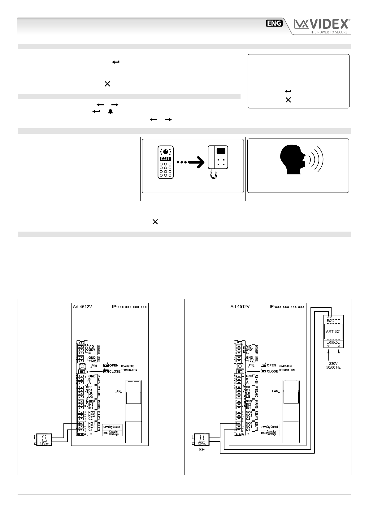
Digital call panel for IP system
Capacitor
discharge
Dry contact
output
INPUTS
IN1
IN2
GNDI
RELAY 2
C2
NC2
NO2
RELAY 1
C1
NC1
NO1
ETICHETTA 1
LAN
+12V
GND
POWER
PROG.
EXT. CAMERA
SL
GNDV
VID
RS485
A
B
GND
WIEGAND
LR
D1
D0
CLOSE
OPEN
RS485
BUS TERMINATION
Made in Italy
E
Q
F
I
L
M
N
G
H
P
O
Fig. 2 Lato posteriore
DESCRIZIONE
ART.4512V, ART.4512V/F
Pannello digitale di chiamata, serie 4000 (placca frontale in
acciaio inox spazzolato, spessore 2mm), per sistemi IP Videx. Il
pannello è compatibile con il sistema modulare della Serie 4000
e ha le dimensioni di due moduli della Serie 4000.
Tutti i pannelli digitali di chiamata, prodotti da Videx, integrano
la possibilità per tutti gli utenti di avere il proprio codice di
accesso unico (ogni appartamento può avere più di un codice
di accesso). Il codice di accesso può includere no a sei cifre e
non è visibile agli estranei. Inoltre, il pannello è integrato con
un lettore di prossimità che consente di memorizzare una
serie di chiavi di prossimità, per utilizzarle singolarmente o in
combinazione con il codice di accesso di ingresso all’edicio.
Oltre alle funzioni di portiere elettrico, il pannello comprende
un display graco LCD 128 x 64 pixel con retroilluminazione in
blu (per visualizzare messaggi graci e di testo che guidano i
visitatori attraverso il pannello operativo) e una tastiera con
18 pulsanti retroilluminati in blu, di cui 6 pulsanti alfabetici
(A..F) e 10 numerici (0..9) oltre ai pulsanti INVIO e CANCELLA.
È possibile eettuare una chiamata ai condòmini digitando il
relativo codice dell'appartamento.
Ad integrare i messaggi visivi forniti dal display, il pannello
dispone della funzionalità dei messaggi vocali con i quali si forniscono informazioni relative al funzionamento del sistema.
La telecamera incorporata è una telecamera CMOS a colori con obiettivo quadrangolare e LED di illuminazione a luce bianca
(l’obiettivo quadrangolare prevede un angolo di vista di 170 gradi). Le interfacce includono una porta Wiegand (sistemi basati su
questa interfaccia ancora non implementati) e un’interfaccia RS-485 per usi futuri.
La capacità di memoria consente di memorizzare no a 10000 dati utente, no a 10000 codici di accesso e no a 10000 chiavi di
prossimità. La nitura del pannello frontale è in acciaio inossidabile spazzolato mentre le niture del telaio sono quelle standard
della Serie 4000.
ART.4512RV, ART.4512RV/F
Come per l’Art.4512V, ma con l’utilizzo di una tastiera a 15 pulsanti retroilluminati in blu, di cui 3 pulsanti di navigazione utilizzati
per il servizio di repertorio nomi e 10 pulsanti numerici (0..9) oltre ai pulsanti INVIO e CANCELLA. È possibile chiamare i condòmini
digitando il relativo numero di appartamento o cercandone il nome con la funzione di repertorio nomi.
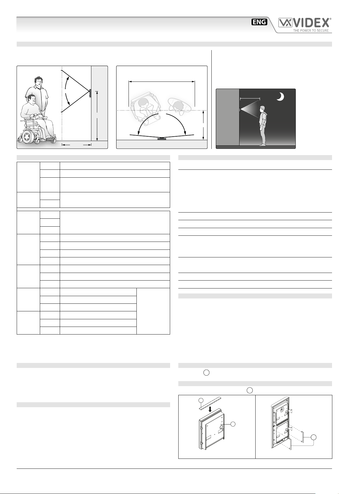
LEGENDA
ALED illuminazione e telecamera
BAltoparlante
CDisplay
DTastiera
EVolume microfono
FVolume altoparlante
GTerminali di collegamento telecamera esterna
HTerminali di collegamento alimentazione
IPulsante bootloader per aggiornamento rmware
LInterruttore terminazione bus RS485
MTerminali connessione bus RS485
N
Terminale collegamento Wiegand (non ancora implementato)
OTerminali collegamento sistema
PJumper modalità operativa relè apri-porta
QInterfaccia Ethernet POE
Per scaricare il software di programmazione
VX IP Wizard ed ottenere gli ultimi
aggiornameni di rmware e manuali è
necessario registrarsi sul sito web
https://service.videx.it/