ADCP-90-326 • Rev B • November 2020
Page 3
© 2020, CommScope Inc.
ADMONISHMENTS
Important safety admonishments are used in this manual to warn of possible hazards to persons or
equipment. The admonishments — in the form of Dangers, Warnings, and Cautions — must be
followed at all times. These warnings are flagged by use of a triangular alert icon (shown below),
and are listed in descending order of severity of injury or damage and likelihood of occurrence.
.
GENERAL SAFETY PRECAUTIONS
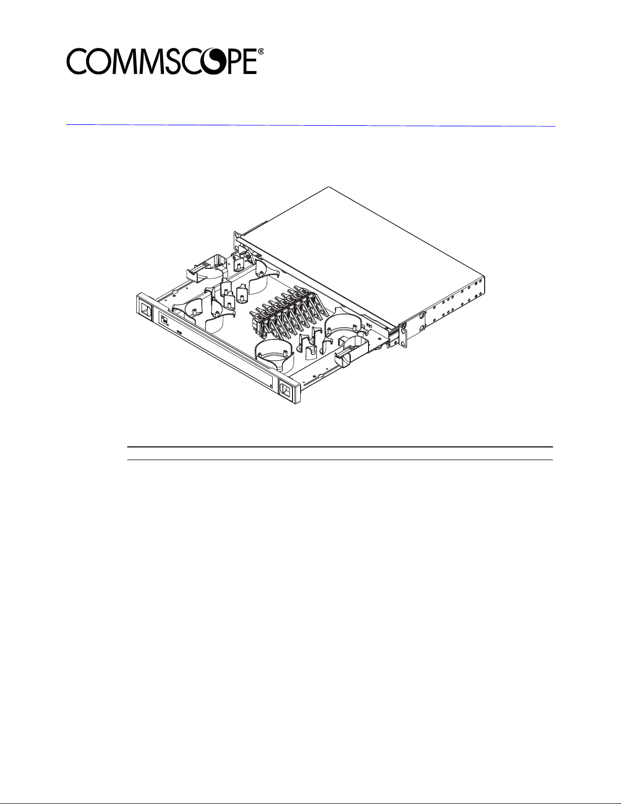
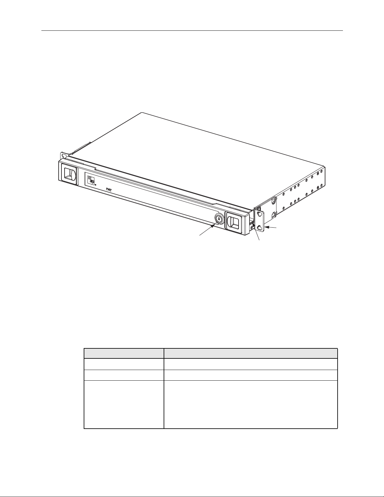
1 PRODUCT DESCRIPTION
The CommScope Fiber Management Tray (FMT) is a rack-mount, front-access fiber optic tray
available in a variety configurations. Some of these are noted below:
• 12- or 16-position termination and storage (universal storage);
• 24-position termination and storage (left or right storage);
• 12-position termination and splice (left or right splice entry);
• 32-, 48-, or 60-cable bulk slack storage (capacity dependent on cable diameter).
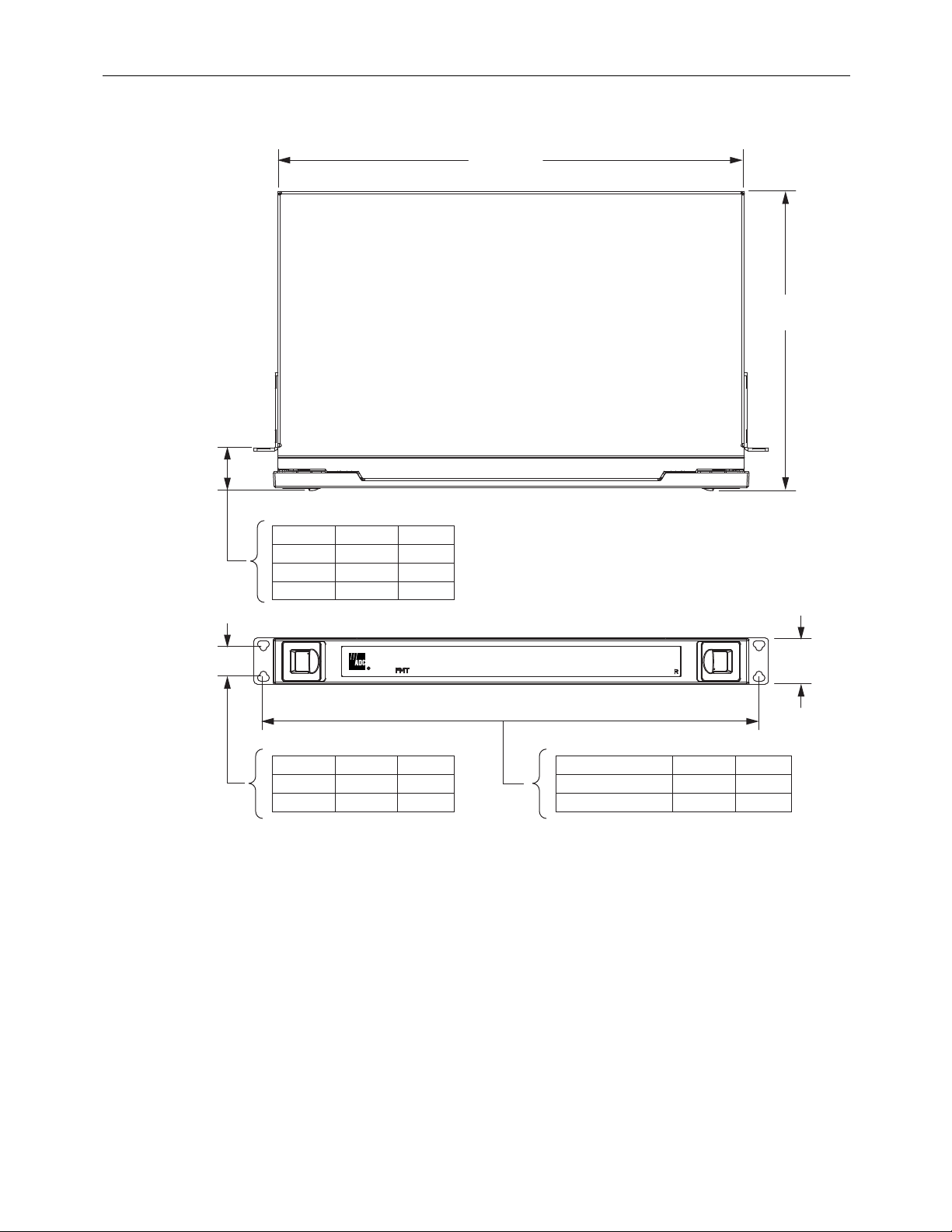
Rack-mount and recess options include:
• EIA or WECO, reversible 19- or 23-inch (48.26 or 58.42 cm) mounting brackets installed
for 5-inch recess;
• ETSI, 20.28-inch (51.5 cm) with 40 mm recess.
Customer adjustable recess configurations include:
• EIA 19-inch (48.26 cm) with 40 mm recess;
• EIA or WECO, 19 or 23-inch (48.26 or 58.42 cm) FMT offer
2.2-inch (5.59 cm), 3.1-inch
(7.9 cm), 5-inch (12.7 cm), or 6.5-inch (16.5 cm) recess;
Danger: Danger is used to indicate the presence of a hazard that will cause severe personal
injury, death, or substantial property damage if the hazard is not avoided.
Warning: Warning is used to indicate the presence of a hazard that can cause severe personal
injury, death, or substantial property damage if the hazard is not avoided.
Caution: Caution is used to indicate the presence of a hazard that will or can cause minor
personal injury or property damage if the hazard is not avoided.
Danger:
Infrared radiation is invisible and can seriously damage the retina of the eye. Do not
look into the ends of any optical fiber. Do not look directly into the optical adapters of the adapter
packs. Exposure to invisible laser radiation may result. An optical power meter should be used to
verify active fibers. A protective cap or hood MUST be immediately placed over any radiating
adapter or optical fiber connector to avoid the potential of dangerous amounts of radiation
exposure. This practice also prevents dirt particles from entering the adapter or connector
.