manuals.online logo
Brands
  1. Home
  2. •
  3. Brands
  4. •
  5. Videx
  6. •
  7. Intercom System
  8. •
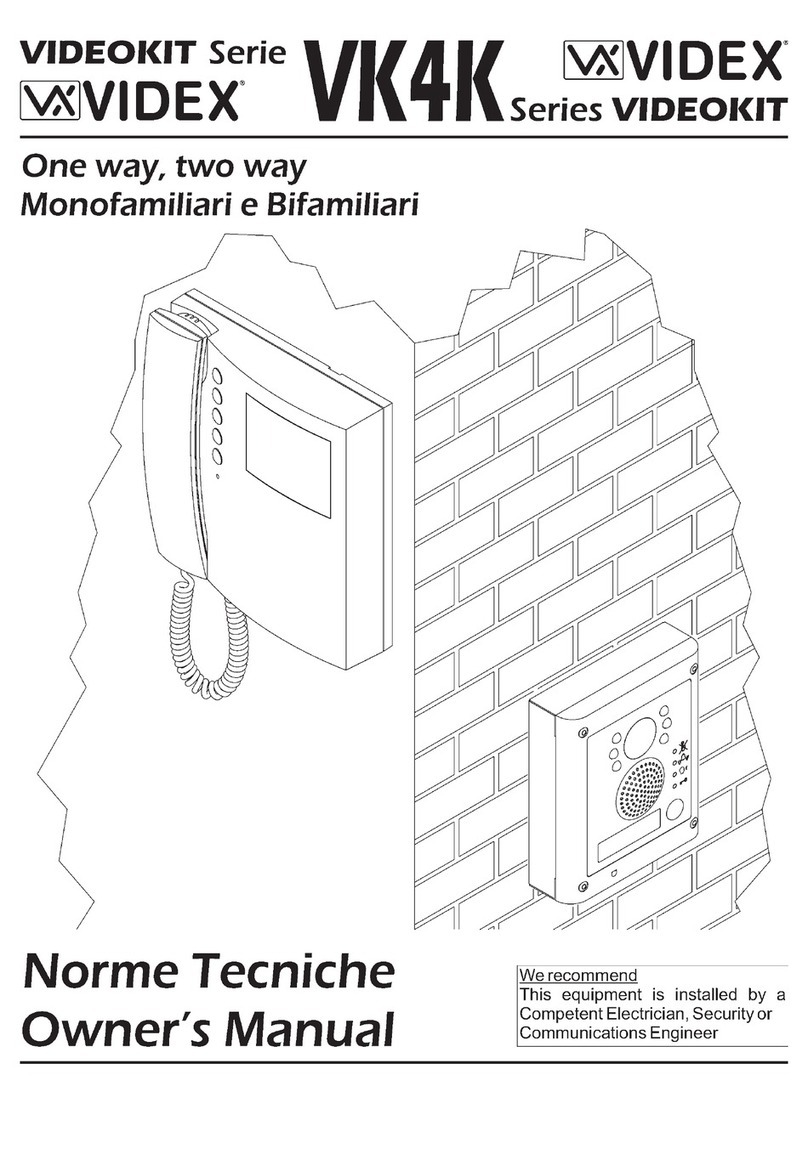
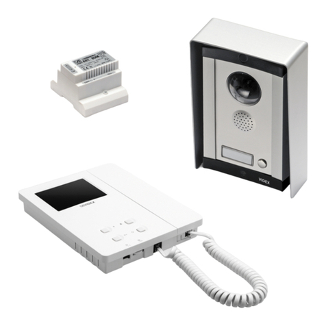
  9. Videx VIDEOKIT ESVK/6286 Series System manual

Videx VIDEOKIT ESVK/6286 Series System manual

This manual suits for next models

19

Other Videx Intercom System manuals

Videx VRVK Series System manual

Videx

Videx VRVK Series System manual

Videx 8000 Series User manual

Videx

Videx 8000 Series User manual

Videx ESVK Series System manual

Videx

Videx ESVK Series System manual

Videx S6200MV User manual

Videx

Videx S6200MV User manual

Videx 4000 Series User manual

Videx

Videx 4000 Series User manual

Videx 4000 Series User manual

Videx

Videx 4000 Series User manual

Videx ESVK User manual

Videx

Videx ESVK User manual

Videx 4000 Series User manual

Videx

Videx 4000 Series User manual

Videx VK4K/3656 Series System manual

Videx

Videx VK4K/3656 Series System manual

Videx Kristallo Series User manual

Videx

Videx Kristallo Series User manual

Videx 4000 Series User manual

Videx

Videx 4000 Series User manual

Videx CVR4KV User manual

Videx

Videx CVR4KV User manual

Videx GSM Lite 4000 Series User manual

Videx

Videx GSM Lite 4000 Series User manual

Videx 4000 Series User manual

Videx

Videx 4000 Series User manual

Videx VK8K/6256 Series System manual

Videx

Videx VK8K/6256 Series System manual

Videx VR4K-2/CL User manual

Videx

Videx VR4K-2/CL User manual

Videx VK6N Series User manual

Videx

Videx VK6N Series User manual

Videx VK4KX System manual

Videx

Videx VK4KX System manual

Videx VANDAL RESISTANT User manual

Videx

Videx VANDAL RESISTANT User manual

Videx ESVK Series System manual

Videx

Videx ESVK Series System manual

Videx ESVK/KRV782 Series System manual

Videx

Videx ESVK/KRV782 Series System manual

Videx ESVK 6388 Series System manual

Videx

Videx ESVK 6388 Series System manual

Videx Kristallo Series User manual

Videx

Videx Kristallo Series User manual

Videx 3000 Series User manual

Videx

Videx 3000 Series User manual

Popular Intercom System manuals by other brands

Auta COMPACT VISUALTECH manual

Auta

Auta COMPACT VISUALTECH manual

Aiphone LC-10S instructions

Aiphone

Aiphone LC-10S instructions

Aiphone PD-1 instructions

Aiphone

Aiphone PD-1 instructions

Aiphone JF-DVF-HID-I instructions

Aiphone

Aiphone JF-DVF-HID-I instructions

Comelit 4893M Technical manual

Comelit

Comelit 4893M Technical manual

MGL Avionics V16 manual

MGL Avionics

MGL Avionics V16 manual

SSS Siedle BVI 750-0 Installation & programming

SSS Siedle

SSS Siedle BVI 750-0 Installation & programming

urmet domus AIKO 1716/1 quick start guide

urmet domus

urmet domus AIKO 1716/1 quick start guide

urmet domus IPerVoice 1039 Installation

urmet domus

urmet domus IPerVoice 1039 Installation

Alpha Communications STR QwikBus TT33-2 Installation, programming, and  user's manual

Alpha Communications

Alpha Communications STR QwikBus TT33-2 Installation, programming, and user's manual

Monacor ICM-20H instruction manual

Monacor

Monacor ICM-20H instruction manual

Logenex A202CR Installation & programming

Logenex

Logenex A202CR Installation & programming

Quantum QR5 Installation and programming manual

Quantum

Quantum QR5 Installation and programming manual

EVGA XR1 quick guide

EVGA

EVGA XR1 quick guide

CyberData 011211 series Installation quick reference

CyberData

CyberData 011211 series Installation quick reference

Vidos duo M1021 user manual

Vidos

Vidos duo M1021 user manual

Savant DOR-SMS-00 Deployment guide

Savant

Savant DOR-SMS-00 Deployment guide

SSS Siedle BTSV 850-03 operating instructions

SSS Siedle

SSS Siedle BTSV 850-03 operating instructions

manuals.online logo
manuals.online logoBrands
  • About & Mission
  • Contact us
  • Privacy Policy
  • Terms and Conditions

Copyright 2025 Manuals.Online. All Rights Reserved.

66550032-EN - V5.0 - 31/10/19
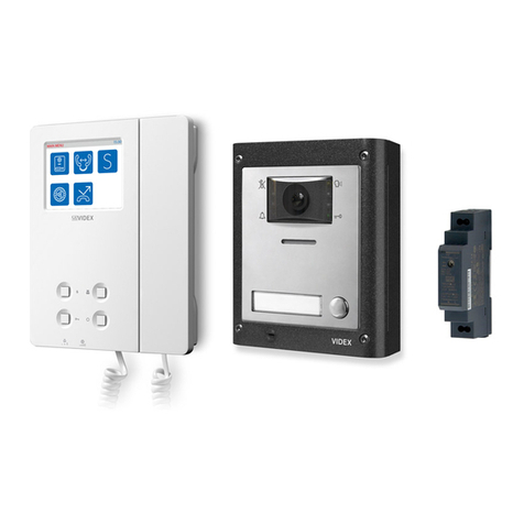
VIDEOKIT
ESVK/6286 SERIES
“2 Wire” bus one way, two way videokit
Installation handbook
6286
We recommend
This equipment is installed by a
Competent Electrician, Security or
Communications Engineer
.
ESVKRev.0.1
ESVKXRev.0.1
ESVKCRev.0.2
66550032-EN - V5.0 - 31/10/19
- 2 -
ESVK/6286 Series “2 wire Bus” videokit
ESVK/6286 Series - Installation handbook
Index
System components and available versions ................................................................................................................................ 3
General directions for installation................................................................................................................................................ 6
Art.4333/4333X Speaker unit module with built-in functional to digital interface................................................................. 8
Art.4901 Digital codelock module.............................................................................................................................................. 13
4000 Series surface and ush mounting door station installation .......................................................................................... 17
Art.6286 3.5" colour display videophone ................................................................................................................................. 19
6200 Series Videophone wall mounting instructions ............................................................................................................... 23
Art.2321-2321/P Power supplies for VX2300 .......................................................................................................................24
Art.2322 Power supply converter from BUS line to 12 Vdc ...................................................................................................... 25
Art.4342 .. 4345 Single row button expansion modules .......................................................................................................... 26
Installation diagrams ................................................................................................................................................................... 28
NOTES AND SUGGESTIONS
• All diagrams refer to all kits versions: ush or surface, colour or black & white.
• Dashed connections refer to optional connections (“Local bell”, “Push to exit” & “Door monitor”).
• Some diagrams show how to connect a 12Vdc electric lock: these directions are suitable for all diagrams in this manual.
• Each time a setting is changed on a videophone (address, extension, number of rings etc.), the videophone must be disconnected from
the relevant connection board then after a few seconds reconnected again to allow the recognizing of the new setting.
• All diagrams shown are valid for B&W or colour systems with surface or ush mount door station.
ADDRESSES 1..12 TABLE FOR DIPSWITCH BANKS WITH ON POSITION UP
= OFF
= ON
12 3 4 5 6 7 8
ON
1
12 3 4 5 6 7 8
ON
2
12 3 456 7 8
ON
3
12 3 4 5 6 7 8
ON
4
12 3 456 7 8
ON
5
12 3 4 5 6 7 8
ON
6
12 3 4 5 6 7 8
ON
7
12 3 4 5 6 7 8
ON
8
12 3 4 5 6 7 8
ON
9
12 3 4 5 6 7 8
ON
10
12 3 4 5 6 7 8
ON
11
12 3 4 5 6 7 8
ON
12
DECLARATION OF RESPONSIBILITY
This manual has been written and revised carefully. The instructions and the descriptions which are included in it are referring to
VIDEX parts and are correct at the time of print. However, subsequent VIDEX parts and manuals, can be subject to changes without
notice. VIDEX Electronics S.p.A. cannot be held responsible for damages caused directly or indirectly by errors, omissions or discrep-
ancies between the VIDEX parts and the Manual.
WE RECOMMEND
This equipment is installed by a Competent Electrician, Security on Communications Engineer
66550032-EN - V5.0 - 31/10/19
- 3 -
ESVK/6286 Series “2 wire Bus” videokit
ESVK/6286 Series - Installation handbook
System components and available versions
ESVK/6286
Colour videokit.
50
43,8
135,0
160,0
45,0 22,7
15,7
143,0
120,0
45,0
INDOOR
STATION
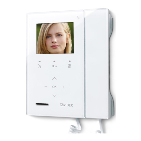
Videophone
Art.6286
pag. 19
ACCESSORIES
Power supply
Art.2321
pag. 24
OUTDOOR
STATION
Flush
Mounting
Surface
Mounting
Camera unit
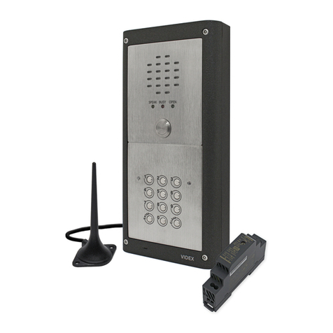
Art.4333
pag. 8
Fig. 1 - ESVK/6286 components (measures in mm)
ONE WAY VERSIONS
ESVK-1/6286 - ush mounting
1 Outdoor station composed of:
1 Art.4333-1: 1 button camera unit
1 Art.4851: Flush mounting box
1 Colour videophone
Art.6286
1 Power supply
Art.2321
ESVK-1S/6286 - surface mounting
1 Outdoor station composed of:
1 Art.4333-1: 1 button camera unit
1 Art.4881: Surface mounting box
1 Colour videophone
Art.6286
1 Power supply
Art.2321
TWO WAY VERSIONS
ESVK-2/6286 - ush mounting
1 Outdoor station composed of:
1 Art.4333-2: 2 buttons camera unit
1 Art.4851: Flush mounting box
2 Colour videophones
Art.6286
1 Power supply
Art.2321
ESVK-2S/6286 - surface mounting
1 Outdoor station composed of:
1 Art.4333-2: 2 buttons camera unit
1 Art.4881: Surface mounting box
2 Colour videophones
Art.6286
1 Power supply
Art.2321
66550032-EN - V5.0 - 31/10/19
- 4 -
ESVK/6286 Series “2 wire Bus” videokit
ESVK/6286 Series - Installation handbook
System components and available versions
ESVKX/6286 Colour videokit with embended proximity key reader.
50
43,8
135,0
160,0
45,0 22,7
15,7
143,0
120,0
45,0
INDOOR
STATION
Videophone
Art.6286
pag. 19
ACCESSORIES
Power supply
Art.2321
pag. 24
Card format fob
Art.955/C
Tag format fob
Art.955/T
OUTDOOR
STATION
Flush
Mounting
Surface
Mounting
Camera unit
Art.4333X
pag. 8
Fig. 2 - ESVKX/6286 components (measures in mm)
ONE WAY VERSIONS
ESVKX-1/6286 - ush mounting
1 Outdoor station composed of:
1 Art.4333X-1: 1 button camera unit
1 Art.4851: Flush mounting box
1 Colour videophone
Art.6286
1 Power supply
Art.2321
1 Card format fob
Art.955/C
2 Tag format fobs
Art.955/T
ESVKX-1S/6286 - surface mounting
1 Outdoor station composed of:
1 Art.4333X-1: 1 button camera unit
1 Art.4881: Surface mounting box
1 Colour videophone
Art.6286
1 Power supply
Art.2321
1 Card format fob
Art.955/C
2 Tag format fobs
Art.955/T
TWO WAY VERSIONS
ESVKX-2/6286 - ush mounting
1 Outdoor station composed of:
1 Art.4333X-2: 2 buttons camera unit
1 Art.4851: Flush mounting box
2 Colour videophones
Art.6286
1 Power supply
Art.2321
1 Card format fob
Art.955/C
4 Tag format fobs
Art.955/T
ESVKX-2S/6286 - surface mounting
1 Outdoor station composed of:
1 Art.4333X-2: 2 buttons camera unit
1 Art.4881: Surface mounting box
2 Colour videophones
Art.6286
1 Power supply
Art.2321
1 Card format fob
Art.955/C
4 Tag format fobs
Art.955/T
66550032-EN - V5.0 - 31/10/19
- 5 -
ESVK/6286 Series “2 wire Bus” videokit
ESVK/6286 Series - Installation handbook
ESVKC/6286 Colour videokit plus a codelock module.
50135,0
280,0
45,0 22,7
263,0
INDOOR
STATION
Videophone
Art.6286
pag. 19
ACCESSORIES
Power supply
Art.2321
pag. 24
Power supply converter
Art.2322
pag. 25
OUTDOOR
STATION
Flush
Mounting
Surface
Mounting
Camera unit
Art.4333
pag. 8
Codelock
unit
Art.4901
pag. 13
Fig. 3 - ESVKC/6286 components (measures in mm)
ONE WAY VERSIONS
ESVKC-1/6286 - ush mounting
1 Outdoor station composed of:
1 Art.4333-1: 1 button camera unit
1 Art.4901: Codelock module
1 Art.4852: Flush mounting box
1 Colour videophone
Art.6286
1 Power supply
Art.2321
1 Power supply
converter
Art.2322
ESVKC-1S/6286 - surface mounting
1 Outdoor station composed of:
1 Art.4333-1: 1 button camera unit
1 Art.4901: Codelock module
1 Art.4882: Surface mounting box
1 Colour videophone
Art.6286
1 Power supply
Art.2321
1 Power supply
converter
Art.2322
TWO WAY VERSIONS
ESVKC-2/6286 - ush mounting
1 Outdoor station composed of:
1 Art.4333-2: 2 buttons camera unit
1 Art.4901: Codelock module
1 Art.4852: Flush mounting box
2 Colour videophones
Art.6286
1 Power supply
Art.2321
1 Power supply
converter
Art.2322
ESVKC-2S/6286 - surface mounting
1 Outdoor station composed of:
1 Art.4333-2: 2 buttons camera unit
1 Art.4901: Codelock module
1 Art.4882: Surface mounting box
2 Colour videophones
Art.6286
1 Power supply
Art.2321
1 Power supply
converter
Art.2322
System components and available versions
66550032-EN - V5.0 - 31/10/19
- 6 -
ESVK/6286 Series “2 wire Bus” videokit
ESVK/6286 Series - Installation handbook
General directions for installation
CABLE TYPES AND CROSS SECTIONAL AREAS
The VX2300 digital system can use several types of cables but depending on their specication will allow dierent distances up to
400 meters maximum. We do not recommend the use of shielded cables because of the high eddy capacitance. It is also not advised
to double up on cables as this will also increase the capacitance. The following table species values of resistance, capacitance and
maximum distances achievable for several types of cables (capacitance and resistance values are referring to 100 metres of cable).
Cable Type** Wires Section (mm2)Resistance (Ohm) per
100 metres
Capacitance (nF) per
100 metres
*Maximum Distance
(metres)
VIDEX CM2 0.50 3.2 8 200m
CAT5 UTP/CW1308 0.22 8 4.9 70m
Std Telephone Cable 0.28 6.5 5.5 100m
Standard wire 0.8 / 1 2 6.5 70m
* The maximum distance represents the maximum distance from power supply. i.e. the cable length between the outdoor sta-
tion and the power supply or between the power supply and the videophone.
There are two important characteristics to consider when calculating cable, the resistance and the capacitance.The resistance
of the cable from power supply to end point must be less than 10 Ohms and can be calculated from point to point.The capac-
itance of the cable must not exceed 40nF and is an accumulation of all lengths and branches of the cable. For example: Videx
CM2 cable can be used for a maximum distance of 200m from door station to power supply and another 200m from power
supply to videophone (400 meters) but this distance may be reduced if the maximum capacitance is reached rst.
When using the block exchanger art. 2306 it is possible to exceed the limit of 400m. The 2306 breaks the system into
smaller systems or blocks, each block can then achieve the 400m.
For example: in a system with two block exchangers:
• Using 100m to reach the rst block, you can then use up to 300m cable in the block;
• Assuming you are using another 50 meters cable to get from the rst to the second block, in the second you can use
(400-100-50) = 250m.
** It is important that the video intercom system cables do not run with mains or other high power cables. Noise from such
cables (electromagnetic interference) may cause noises on audio/video and lost functionality. In cases where this advice
can not be followed or when existing cables are to be used it will be necessary to carry out tests to assess the quality and
functionality of the installation.
In case of use of cables not in conformity with above specication it is possible to experience deterioration of digital and video signals.
We suggest to use twisted cables with maximum resistance of 10 Ohm (between the furthest door station and the furthest video-
phone) and maximum capacitance of 40nF (this value must be calculated considering all the cables used in the system; the capac-
itance/metres value is normally specied on the cable package or directly on the cable).
BUS DEVICE SETUP AND VIDEO DISTRIBUTION
• When changing dip switch settings, disconnect the device from the bus for a minimum of 1 minute to allow the unit to fully discharge.
• When you have more than one device in the same apartment, all the devices must be connected to the same video distributor (Art.317N):
this means that you cannot use two video distributors Art.318 for one apartment where you have 3 or 4 videophones/intercoms.
• After completing the installation proceed to testing. The video level gain can be adjusted at several points including distributors,
entrance exchanger and bus boosters.
HOW TO CONNECT A LOCAL POWER SUPPLY
The drawing below shows how to connect a local power supply when required (i.e. when you have 4 videophones with the same
address that must be switched on at the same time). In both cases switch 4 of SW3 must be set to the ON position.
NOTE! OBSERVE CONNECTION POLARITIES AS SHOWN IN THE DIAGRAM BELOW.
0V
230V
+
_
BUS
Art.2321
Videophone:
Extension N.
1
1
ART.6286
0V
230V
+
_
BUS
Art.2321
5
4
3 8
7
6
ON
21 4
3
ON
21
Videophone:
Extension N.
BUS1
BUS2
GND
+12VM
GND
+DOL
AL-LB GND
LB
AL
-DOL
+VAUX
C
NO
JP1
1
1
ART.6388
66550032-EN - V5.0 - 31/10/19
- 7 -
ESVK/6286 Series “2 wire Bus” videokit
ESVK/6286 Series - Installation handbook
General directions for installation
CABLES LENGTH
Videx Electronics S.p.A.
Via del Lavoro 1, 63846 Monte Giberto (FM)
Phone: +39 0734 631669 - Fax +39 0734 631669
www.videx.it - info@videx.it
Autore:
Data modifica:
Data creazione:Title:
Notes:
Titolo:
Note: Cod.File:
Foglio
/11
Marco Rongoni
vx2300cla.dw
g
29/05/2019
29/05/2019
Art.2321
BUS
Art.317N
Art.6488Art.6286
Art.KRV86
A = Max 200m
B+C = Max 200m
Using Cable TW2 - Usando Cavo TW2
Art.6788
A
B
D C
EF
B+D = Max 200m
B+E = Max 200m
B+F = Max 200m
A+B+C+D+E+F = Max 400m
66550032-EN - V5.0 - 31/10/19
- 8 -
ESVK/6286 Series “2 wire Bus” videokit
ESVK/6286 Series - Installation handbook
Art.4333/4333X
Speaker unit module with built-in functional to digital interface
ED
C
A
F
B B
Fig. 1
STEEL
ALI
HIGH BRASS
MATTE
4333-1
4333-0
4333-2
4333X-1
4333X-0
4333X-2
Made in Italy
BUS
PTE
GND
C
BUS
GND
NO
VID2
+V2
EB2
GNDV
EB1
GND
+C
VAUX
NC
Balance
1 2 3 4 5 6 7 8
ON
G
H
I
J
K
Fig. 2
DESCRIPTION
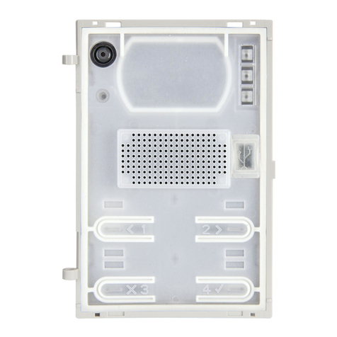
Speaker unit module with built-in colour camera with autoiris lens and white light illumination LEDs. Depending on the speaker
unit version it includes one or two call push buttons. The unit circuitry incorporates:
• An embedded proximity key reader (Art.4333X only);
• The transmitting amplier with microphone and volume control;
• The receiving amplier with volume control;
• The audio balance circuit with“BALANCE”control;
• The enslavement relay to enable the electric lock (3 contacts: common, normally open and normally closed). It can work also as
capacitor discharge to supply directly the electric lock;
• The call buttons from 1 to a maximum of 2 depending on the module version;
• The illumination LEDs for the card name holder;
• The camera comprised of illumination LEDs.
MODULE DETAILS:
ACamera with illumination LEDs;
BOperation LEDs;
CLoudspeaker;
DCard name holder with built-in proximity reader;
ECall push button (0, 1 or 2 depending on the model);
FMicrophone;
GBalance Control;
HLoudspeaker volume control;
IMicrophone volume control;
JDip-switch to carry out the following programming:
• Door station ID (switches from 1 to 3);
• Door opening time (switch 4 and 5);
• Conversation time (switch 6);
• Address order (switch 7);
• Main camera selection (switch 8);
KSystem connection terminals.
AVAILABLE MODULE VERSIONS
Art.4333-0
Art.4333-1
Art.4333X-1
Art.4333X-0
Art.4333-2
Art.4333X-2
Rev.0.1
66550032-EN - V5.0 - 31/10/19
- 9 -
ESVK/6286 Series “2 wire Bus” videokit
ESVK/6286 Series - Installation handbook
Art.4333/4333X Speaker unit module with built-in functional to digital interface
FRONT LEDS SIGNALLING DESCRIPTION
When illuminated, indicates that it is not possible to make a call because a call or a conversation is in progress (from
the outdoor station from which you are calling or from another outdoor station on systems with multiple entranc-
es). The LED will be o when the system is in stand-by,
If illuminated, indicates that the call from the outdoor station is in progress. The LED will switch OFF when the call
is answered or after the programmed number of rings.
If illuminated, indicates that it is possible to speak because the call has been answered. The LED will switch OFF at
the end of a conversation (or at the end of the conversation time).
If illuminated, indicates that the door lock has been operated. It will switch OFF at the end of the programmed
“door opening” time.
PROGRAMMING
The programming consists of the following settings:
• Unit ID (1..8);
• Door Opening Time (1, 2, 5 or 10 seconds);
• Conversation Time (1 or 2 minutes);
• Addressing order of the buttons.
• Main camera selection
The settings are carried out through the 8 way dip-
switch (reference Jon Fig. 2) accessible from the
rear side of the module.
UNIT ID
Switches ID
123
OFF OFF OFF 1
ON OFF OFF 2
OFF ON OFF 3
ON ON OFF 4
OFF OFF ON 5
ON OFF ON 6
OFF ON ON 7
ON ON ON 8
DOOR OPENING TIME
Switches Seconds
4 5
OFF OFF 1
ON OFF 2
OFF ON 5
ON ON 10
CONVERSATION TIME
Switch Minutes
6
OFF 1
ON 2
ADDRESSES ORDER
Switch Sort Switch Sort
7 7
OFF
1
2
8
9
10
11
12
3
4
5
6
7
EB2
EB1
ON
11
12
6
7
8
9
10
1
2
3
4
5
EB2
EB1
Art.125 required. When Art.125 is used, follow the directions in the diagram to supply the push buttons modules.
MAIN CAMERA SELECTION
Switch Selection
8
OFF Main camera internal
ON Main camera external
MAXIMUM ILLUMINATION DISTANCE FROM CAMERA AT NIGHT
The illumination LED’s within the camera will illuminate the visitor when they are within 50cm of the camera.
MAX 50 cm
66550032-EN - V5.0 - 31/10/19
- 10 -
ESVK/6286 Series “2 wire Bus” videokit
ESVK/6286 Series - Installation handbook
Art.4333/4333X Speaker unit module with built-in functional to digital interface
PROGRAMMING TAGS FOR ART.4333X
MASTER TAG
The external module is supplied with a master tag. The master tag is programmed in-factory, it is white to easily stand out. This tag
enables user tags to be programmed or cleared.
If the master tag is lost, a new one will have to be ordered and a specic procedure performed to program it on the external module.
In this instance, it will be necessary to reprogram all the user tags.
USER TAG
The user tags can be programmed on the external module using the master tag to access programming mode:
1. Place the master tag in front of the tag reader.
↪The external module emits two high-pitched “bip”.
BIP BIP
2. Press the call button (the lower call button in the case of a 2-button external module).
↪The external module emits a low-pitched continuous “beeping” sound.
BIIIIIIP
3. Release the call button.
↪The low-pitched “beeping” sound stops.
4. Place the user tag to be programmed in front of the tag reader.
↪The external module emits a high-pitched “beeping” sound, the tag is programmed. If you do
not remove the tag quickly, may be emitted the alert for an already programmed tag.
BIP
5. Repeat the step 4 for each tag to program.
Note: the external module emits three low-pitched “beeping” sounds if an already programmed
tag is placed in front of the tag reader.
BIP BIP BIP
Note: the external module emits three high-pitched “beeping” sounds to indicate that its
memory is full (50 tags maximum). In this instance, it is not possible to program new tags.
BIP BIP BIP
6. To exit programming mode:
» place the master tag in front of the tag reader, or
» wait 10 seconds after the most recent programming operation.
↪ The external module emits two low-pitched “beeping” sounds in order to indicate
that it is in operational mode.
BIP BIP
USING TAGS
Place a tag in front of the tag reader:
↪If the tag is programmed, the external module emits two high-pitched “beeping” sounds
and its relay is activated.
BIP BIP
↪If the tag is not programmed, the external module emits three low-pitched “beeping”
sounds and its relay is not activated.
BIP BIP BIP
CLEARING USER TAGS
The following procedure will clear the programming on all user tags.
Clearing the user tag programming is carried out on the external module using the master tag to run the procedure:
1. Place the master tag in front of the tag reader.
↪The external module emits two high-pitched “bip”.
BIP BIP
2. Press the call button (the lower call button in the case of an external 2-button module) BIP.
↪The external module emits a low-pitched continuous “beeping” sound.
BIIIIIIP
3. Release the call button.
↪The low-pitched “beeping” sound stops.
4. Press and hold down the call button and place the master tag in front of the tag reader.
↪The external module emitts two low-pitched “beeping” sounds, all user tags have been
cleared and the external module exits programming mode.
BIP BIP