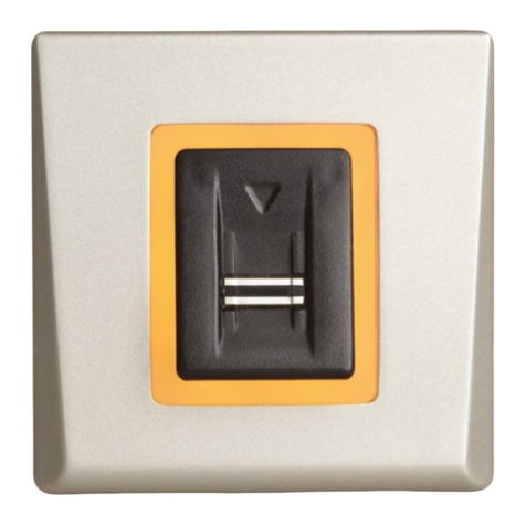
Videx 4000 Series User manual

66250203 - V4.4 - 15/05/22
- 1 -
4000 Series Vandal Resistant Range
Art.4212 - Installation instructions
Art.4212 Audio/video digital front panel
Wide angle colour
camera
Speaker
Display
Keyboard
Art. 4212V Art. 4212RV
Fig. 1 Front view
12T
GNDV
V2/V
V1
PTE
TRD
NO
C
NC
SL
BS
L
¢
+12
GND OC OUTPUT
D0
D1
LR
LG
WIEGAND
A
B
GND
RS485
Dry contact output
Capacitor discharge
RS485
BUS TERMINATION
Open
Close
Balanced V1, V2
Coax V2=V
V1 not used
Balance
V.PB.CHIP
Made in Italy
12T
GNDV
V2/V
V1
PTE
TRD
NO
C
NC
SL
BS
L
¢
+12
GND OC OUTPUT
D0
D1
LR
LG
WIEGAND
A
B
GND
RS485
Dry contact output
Capacitor discharge
RS485
BUS TERMINATION
Open
Close
Balanced V1, V2
Coax V2=V
V1 not used
Balance
V.PB.CHIP
Made in Italy
Voice annunciation
speech adjustment
Speaker
volume adjustment
RS485
bus termination switch
RS485
bus connection terminals
Wiegand
connection terminals
Connection
terminals
Video signal setup
switch
Door Open Relay
Operating Mode jumper Audio balance
adjustment
Microphone
volume adjustment
Fig. 2 Back view
Rev.0.1

66250203 - V4.4 - 15/05/22
- 2 -
4000 Series Vandal Resistant Range
Art.4212 - Installation instructions
Art.4212 Audio/video digital front panel
DESCRIPTION
ART.4212V, ART.4212V/F, ART.4212V/SA, ART.4212
4000 Series Vandal resistant (front plate in brushed stainless with 2mm thickness) digital call panel forVidexVX 2200 digital systems (2 wire
BUS audio, 6 wire BUS video). This panel is compatible with the 4000 Series modular system and has the size of two 4000 Series modules.
Complementing all digital door panels manufactured by Videx is the ability for all users to have their own unique access code (each
apartment can have more than one access code). The access code can have up to six digits and is blind to onlookers. Also,integrated
into the panel is a proximity reader enabling a number of proximity fobs to be stored and used individually or in combination with
the access code to enter the building. In addition to the speaker unit functions, the panel includes a 128 x 64 pixel graphical LCD
display with blue back light (to provide text and graphical messages in multiple languages guiding a visitor through the panel op-
eration) plus a keypad with 18 blue back lit buttons 6 of which are alpha buttons (A..F), 10 are numeric buttons (0..9) plus and
buttons. The tenants can be called by dialling the relevant apartment code.
To complement the visual messages provided from the display, the panel has the voice annunciation facility (optional chip installation)
to supply audio messages concerning the system operation. The built-in camera (excluding Art.4212 and Art.4212R) is a colour CMOS
wide angle camera with white light illumination LED’s (the wide angle camera provides a viewing angle of 170 degrees). The camera
can be set to work with composite video signal (coax cable) or balanced video signal (one twisted pair). Interfaces include a Wiegand
output (for systems based on this interface) plus two serial interfaces (USB and RS-485) both allow for programming and event logging.
The programming menu and the setup menu are protected by two passwords with dierent login levels (the engineer password that
grants full access and the system administrator password that is limited to some specic settings) while if you operate from a PC an“En-
gineer’s Password”is requested to program the unit. A“Trade Code” function is available (for periodic visitors) enabled by the specic
input or by programmable time band and “Direct Call Mode”for small installations (up to 10 apartments).
The memory capacity allows to store up to 998 users data, up to 2800 access codes, up to 2800 proximity keys and up to 4000
events. The front panel nish is brushed stainless steel while the frame nishes are the standard oered in the 4000 Series.
ART.4212RV, ART.4212RV/F, ART.4212RV/SA, ART.4212R
As Art.4212V but using a keypad with 15 blue back lit buttons 3 of which are navigation buttons used for the repertory name facility, 10 are
numeric buttons (0..9) plus and buttons. The tenants can be called by dialling the relevant apartment number or by searching the relevant
name using the repertory name function.
AUDIO/VIDEO VERSIONS
Art.4212V
For 4000 Series mod-
ular system, ush or
surface mounting.
Art.4212RV
For 4000Series
modular system, ush
or surface mounting,
with repertory name.
Art.4212V/F
Flush version.
Art.4212RV/F
Flush version with
repertory name.
Art.4212V/SA
Surface version.
Art.4212RV/SA
Surface version with
repertory name.
AUDIO ONLY VERSIONS
Art.4212
For 4000 Series mod-
ular system, ush or
surface mounting.
Art.4212R
For 4000Series
modular system, ush
or surface mounting,
with repertory name.

66250203 - V4.4 - 15/05/22
- 3 -
4000 Series Vandal Resistant Range
Art.4212 - Installation instructions
Art.4212 Audio/video digital front panel Operation
OPERATION
STANDBY MODE
The display alternates between HOME1 page and logo (if enabled - see "Home 2" on
pag. 8).
HOME1 (shown in Fig. 3)is composed by 4 lines:
• rst line contains date, time and symbol (if enabled - see "RFID" on pag. 12).
Date and time have the format specied by date format and clock format (see pag. 8);
• second, third and fourth lines are edited from Home parameters menu (see "Line 1,
2, 3" on pag. 8) ;
The switching time between HOME1 and logo is specied by Switch parameter on
Home parameters menu (see pag. 8).
Press the “0” button to enter the coded access mode.
Press or (only for 15 button panels) to scroll through the users. (see "Scrolling users" on pag. 3).
Use the numeric keypad followed by to call an apartment (see "Flat" on pag. 7).
Passing a valid and enabled card/fob in front of symbol will open the door.
HOW TO INSERT A CODE
From stand-by mode, pressing “0” will enter the code mode (see Fig. 4).
Every inserted digit is displayed as a dot. will conrm the code.
The following codes can be entered:
• Master code to enter Programming menu (see "Master" on pag. 10);
• Admin code to enter Programming menu with restricted permission (see "Admin"
on pag. 10);
• Trade code to open door (if enabled - see "Trade" on pag. 10);
• a valid Access code , the door will be open, or “NOT FOUND!” message will appear.
To delete digits or exit page press .
HOW TO CALL AN APARTMENT
From stand-by mode, enter a at number (see Fig. 5).
Each digit will be displayed. Pushing will conrm the at number.
If at number is present in memory and user is enabled then a call request is made, or
“NOT FOUND!” message will appear.
To delete digits or exit page press .
SCROLLING USERS
From stand-by mode, pressing or will begin scrolling. The highlighted central line is the selected user: pressing or will
make a call request.
For 15 button panel version scrolling is made using or , for 18 button version “A” and “C” buttons are used.
Callers can press a lettered key to jump to users beginning with that letter. The letter will appear next to the
abc
symbol.
If no users are found with that letter the panel will revert to the previous selection.
HOW TO MAKE A CALL
A call request can be made by either scrolling the user name or entering the at num-
ber. When a call is in progress the panel will show“Calling”as in Fig. 6.
The “CALLING” message alternates with at number (if user has made a call by typing
number) or name (if the scroll was used).
If bus is busy or intercom is not present, “BUSY!” message will appear on the screen. If
no answer after 40 seconds the call will be cleared.
If the call is answered a conversation can begin.
10:30 29/12/2015
VIDEX ELECTR.
FLAT 3
WELCOME
Fig. 3
to conrm
to canc
Code: • • • • • •
Fig. 4
123
to conrm
to canc
Fig. 5
calling
Fig. 6

66250203 - V4.4 - 15/05/22
- 4 -
4000 Series Vandal Resistant Range
Art.4212 - Installation instructions
The display will be as per Fig. 7. The conversation timeout is programmable parameter
speech time (see "Speech time" on pag. 9) in seconds. If the door is released this
time is reduced to 10 seconds.
When the door is released, the animation appears on the screen and to the right of that
the following information is displayed:
• Flat number or name;
• block Id (if system works in MAIN MODE - see "Panel mode" on pag. 11);
• oor (if in NORMAL MODE - see "Mode" on pag. 11);
To delete a call request or close a converastion press . The panel will show the
“CALL END” message.
HOW TO TYPE TEXT
Text typing with Art.4212 is similar to mobile phone text typing. This table shows the characters and symbols that can be typed by
pressing one or more times the keypad numeric push buttons. The alphabetic push buttons “ ”, “ ” and “ ”are used for special
functions:
-“ ”to scroll back;
-“ ”to scroll forward;
-“ ”to alternate between capital and lower case letters.
For instance, to type the name“VIDEX” it is necessary to press:
3 times “8” button =“V”;
3 times “4” button =“I”;
1 times “3” button =“D”;
2 times “3” button =“E”;
2 times “9” button =“X”;
The cursor moves forward when, after inserting a character, the same button is not pressed for more than one second or a dierent
button gets pressed.
Press no. of
times
Key
1 2 3 4 5 6 7 8 9 10 11 12 13
1space . & ! : = # @ " 1
2a b c 2
3d e f 3
4g h i 4
5j k l 5
6m n o 6
7p q r s 7
8t u v 8
9w x y z 9
0+ - * , 0 • _
Scroll back
Alternate between capital and lower case
Scroll forward
ACOUSTIC SIGNALS
Name Signal Event
Key Tone Single beep Key press.
Overow Tone/
Error Tone
Quadruple quick beep • When user inserts a numeric value that exceed the maximum value;
• When searching a user by letter and no users are found (last inserted character
is deleted);
• When saving data to memory fails.
Tag Tone Double beep When a fob or a card is passed in front of RFID antenna.
Save Tone Long single beep When saving data in memory is successful.
Open Door Tone Triple beep When door is opened.
1 CONCIERGE
Fig. 7
Art.4212 Audio/video digital front panel Operation

66250203 - V4.4 - 15/05/22
- 5 -
4000 Series Vandal Resistant Range
Art.4212 - Installation instructions
PROGRAMMING
TO ENTER PROGRAMMING MODE
From standby mode:
• press “0” to enter the coded access mode;
• enter the Master code (with engineer permissions - see "Master" on pag. 10) or Admin code (with limited permissions - see
"Admin" on pag. 10);
• press to enter the code or to delete characters or exit access code mode;
• if entered code isn’t stored in memory, panel will show “NOT FOUND!”.
ADDING USERS
From Programming menu (Fig. 8):
• press “1” to enter the user menu;
• then press “2” to add a new user;
• The adding a new user routine is dierent depending on on if the panel mode is
COMPATIBILITY MODE or NORMAL MODE:
» In COMPATIBILITY MODE, user can add elds in following order:
NAME -> FLAT -> CODE -> FLOOR -> ENABLE -> PHONE -> BLOCK (only in MAIN
MODE);
» In NORMAL MODE:
NAME -> FLAT -> FLOOR -> ENABLE -> PHONE -> BLOCK (only in MAIN MODE);
• At the end of the routine the system checks if the user can be saved to memory.
New item is invalid when Phone ID and Block ID are equal to another one in memory and the at number doesn’t match. In this
case a “ALREADY IN MEMORY” message will appear.
To modify users please refer "User parameters" on pag. 7.
CODE MANAGEMENT
This routine is only valid in NORMAL MODE. When in COMPATIBILITY MODE, please refer to "User parameters" - "Code" on pag. 7.
From Programming menu:
• press “1” to enter the user menu then “1” to modify a user.;
• nd the user by name or at;
• press “3” and enter in User Code menu;
HOW TO ADD A CODE
• press “3” to add a code;
• insert code;
• if code is not already in memory, display will show “ITEM SAVED”, or “ALREADY IN MEMORY” with corresponding acoustic signals.
Note: if in Code + fob mode. Adding a code will automatically be followed by inserting a fob.
HOW TO MODIFY A CODE
• press “1” to modify a code;
• insert code. If searched code is present, panel enters user Code modify page;
• press “1” to enable or disable code;
• press “2” to edit the code;
• type access code;
• press to save or to delete characters or exit edit mode without saving. If code is not already in memory, display will show
“ITEM SAVED”, else “ALREADY IN MEMORY” with corresponding acoustic signals.
HOW TO DELETE A CODE
• press “2” to enter in User Code Delete menu;
• press “1” to delete single item or “2” to delete all codes linked with selected users;
» if user has previously selected the “All” option, panel will delete all codes linked with selected user and “DELETED MESSAGE” will appear;
» if user has previously selected “Single” the panel will enter the User Code Search:
› if searched code is present, panel will show”ITEM SAVED” message;
› if searched code isn’t present in memory, panel will show “NOT FOUND!”.
QUICK CALL
This feature allows the user to set a favorite user (only one) to be called quickly by simply pressing the button.
The call will begin only if the selected user is enabled (see user parameter "Enable" on pag. 7 ).
NOTE: this function is only available for Art.4212RV, Art.4212RV/F, Art.4212RV/SA and Art.4212R.
1: 2: 3:
4: 5: 6:
Prog. Menu fw version X.X.X
Fig. 8
Art.4212 Audio/video digital front panel Programming

66250203 - V4.4 - 15/05/22
- 6 -
4000 Series Vandal Resistant Range
Art.4212 - Installation instructions
SETTING QUICK CALL USER
• enter programming mode as Master (see "How to insert a code" on pag. 3);
• from the main programming (Fig. 8), press “1” to enter the user menu;
• then press “3” for the scrolling user menu (the current quick call shows the icon after the name);
• User the scroll keys and then press to select the user. The message “ITEM SAVED” will appear if the parameter is correctly saved.
DELETING QUICK CALL USER
• enter programming mode as Master;
• from the main Programming menu (Fig. 8), press “1” to enter the user menu;
• then press “4”to delete the parameter from the memory. The message “ITEM DELETED” will appear if the parameter is correctly
removed.
KEY MANAGING
From Programming menu:
• from the main menu press “1” to enter the user menu;
• select user searching by name or at;
• Press “8” to enter user tag menu;
HOW TO ADD A KEY
• press “3” to add a key: the dislpay will show “INSERT KEY” as shown in Fig. 9
• pass the key over the symbol;
• if key is not already in memory display will show “ITEM SAVED”, or “ALREADY IN
MEMORY”with corresponding acoustic signals.
NOTE: when security mode is Code + Fob it is not possible to add a fob in this way. It
must be added with a code in the code menu..
HOW TO MODIFY A KEY
• press “1” to enter the User Tag Search menu;
• press “1” to search by number or “2” to search by key;
» if user has previously select search by number option, he has to enter the key number;
» if user has previously select search by key option, he has to pass card/fob over the symbol;
• if searched key is present, the user tag modify page will appear: pressing “1” to enable/disable the key;
• press to save or to exit without saving.
If searched key isn’t present in memory, panel will show “NOT FOUND!”.
HOW TO DELETE A KEY
• press “2” to enter the User Tag Delete menu;
• press “1” to delete single key or “2” to delete all keys linked with selected users;
» if user has previously select “All”, all keys associated with that user will be deleted, “DELETED MESSAGE” will appear;
» if user has previously select “Single” a search will be needed to locate the key:
› press “1” to search by number or “2” to search by key;
– if user has previously selected search by number, the key number must be entered;
– if user has previously selected search by key, pass the card/fob over the symbol.
› if searched key is present, panel will show ”ITEM SAVED” message;
› if searched key isn’t present in memory, panel will show “NOT FOUND!”.
to exit
Insert key
Fig. 9
Art.4212 Audio/video digital front panel Programming

66250203 - V4.4 - 15/05/22
- 7 -
4000 Series Vandal Resistant Range
Art.4212 - Installation instructions
PROGRAMMING PARAMETERS
USER PARAMETERS
User par. menu Parameter Name Programming Method Permission Default value
1: Usr User name By panel and PC software All “ “
2: Flat Flat By panel and PC software All /
3: Code Code By panel and PC software All /
4: Fl. Floor By panel and PC software All /
5: En. Enable By panel and PC software All Enabled
6: Ph. Id Phone Id By panel and PC software Only Engineer /
7: Bl. Id Block Id By panel and PC software Only Engineer /
8:Tag Tag By panel and PC software All /
USER NAME
The user name can be up to 16 characters long and is displayed
during searching and calling.
Modify routine
• select user searching by name or at;
• press “1” button to enter into edit mode;
• type name;
• press to save or to delete characters or exit edit mode
without save.
FLAT
The at number is entered by the visitor to call a at. It can be 1
to 6 digits long.
Modify routine
• select user searching by name or at;
• press “2” button to enter into edit mode;
• type at number;
• press to save or to delete characters or exit edit mode
without save.
CODE
Access Code is entered by the user to open the door.
Modify routine depends on Mode setting: in COMPATIBILITY
MODE only one code is possible per user. Pressing “3” will allow
the code to be edited.
In NORMAL MODE multiple codes can be assigned to a user.
This routine is described in "Code management" on pag. 5
In both cases codes can be from 3 to 6 digits using keys 0 - 9. It
can be disabled by leaving it blank.
Modify routine (only for COMPATIBILITY MODE)
• select user searching by name or at;
• press “3” to enter into edit mode;
• type new access code;
• press to save or to delete characters or exit edit mode
without saving.
FLOOR
The oor eld displays the oor number of the user called. It is avail-
able only in NORMAL MODE and can be any value from“1”to“250”.
Modify routine
• select user searching by name or at
• press “4” to enter into edit mode;
• type oor number;
• press to save or to delete characters or exit edit mode
without save.
ENABLE
It species whether User is enabled or not. If a visitor tries to call
a disabled user typing the at number, display will show “NOT
FOUND” otherwise the intercom for that at will be called. In-
tercom specied by Phone Id and Block Id.
Modify routine
• select user searching by name or at;
• press “5” to enter into edit mode;
• press “5” to enable or disable;
• press to save or to exit edit mode without save.
PHONE ID
The phone ID represents the address of the intercom to call (Set
by the 8 way dip switches in the intercom).
Modify routine
• select user searching by name or at;
• press “6” to enter into edit mode;
• type Phone Id number;
• press to save or to delete characters or exit edit mode
without save.
BLOCK ID
Block Id eld species the address of Art.2206N. It can assume
values from “1” to “15”. This eld is visible only if the panel is set
to MAIN MODE (see "Panel mode" on pag. 11).
Modify routine
• select user searching by name or at;
• press “7” to enter into edit mode;
• type Block Id number;
• press to save or to delete characters or exit edit mode
without save.
TAG
The tags (key or fob) allow users to open the door. Three fob
code lengths are supported (2, 3 & 4 bytes). It is specied by Tag
width parameter (see "Fob width" on pag. 12).
User can be linked to more than one access code. The modify
routine is described in "Quick call" on pag. 5.
Art.4212 Audio/video digital front panel Programming

66250203 - V4.4 - 15/05/22
- 8 -
4000 Series Vandal Resistant Range
Art.4212 - Installation instructions
HOME PARAMETERS
Home par. menu Parameter Name Programming method Permission Default value
1: Line 1 Line 1 By panel and PC software All /
2: Line 2 Line 2 By panel and PC software All /
3: Line 3 Line 3 By panel and PC software All /
4: Home 2 Home 2 By panel and PC software All Disabled
5: Switch Time Switch time By panel and PC software All 2 s
LINE 1, 2, 3
Each line can be up to 16 characters long and will appear on the
main screen in standby. Enter the string and press . The have
a blank line enter one or more space characters.
Modify routine
• press “1”, “2” or “3” to enter into edit mode;
• enter the string;
• press to save or to delete characters or exit edit mode
without saving.
HOME 2
To enable a second screen which can display a logo.
Modify routine
• press “4” button to enter into edit mode;
• press “4” to enable or disable;
• press to save or to exit edit mode without saving.
SWITCH TIME
Time delay when switching between the two main screens.
Modify routine
• press “5” to enter into edit mode;
• enter time is seconds: it must be between“1“ and “250”;
• press to save or to delete characters or exit edit mode
without saving.
TIME PARAMETERS
Time par. menu Parameter Name Programming method Permission Default value
1: Clock Clock format By panel and PC software All 0-23
Clock By panel and PC software All /
BST/GMT Enable/disable By panel All Enabled
2: Date Date format By panel and PC software All European
Date By panel and PC software All /
Day By panel All /
3: Trade Trade enable By panel and PC software All Disabled
Trade start By panel and PC software All /
Trade end By panel and PC software All /
4: Relay Time Relay time By panel and PC software Only Engineer 2 s
5: Speech Time Speech time By panel and PC software Only Engineer 120 s
CLOCK FORMAT
It changes the clock format shown on the home page.
Select either 12 hour or 24 hour clock format.
Modify routine
• press “1” to enter the clock menu;
• press “1” to enter into edit mode;
• press “1” to switch from 1-12 to 0-23 and viceversa;
• press to save or to exit edit mode without saving.
CLOCK
Set the time on the door panel.
Modify routine
• press “1” to enter the clock menu;
• press “2” to enter edit mode;
• enter the hour, minutes and seconds (all elds are composed of
two digits). After entering two digits to set the hour it automat-
ically advances to the minutes and then to seconds.If in 12 hour
clock format, after seconds it is possible to select AM/PM;
• After setting the last parameter the time will be saved.
Art.4212 Audio/video digital front panel Programming

66250203 - V4.4 - 15/05/22
- 9 -
4000 Series Vandal Resistant Range
Art.4212 - Installation instructions
Art.4212 Audio/video digital front panel Programming
BST/GMT ENABLE/DISABLE
Enable or disable BST/GMT automatic Summer/Winter time
adjustment.
Modify routine
• press “3” to enter edit mode;
• in edit mode, press “3” to enable or disable the facility;
• press to save or to exit edit mode without saving.
DATE FORMAT
It changes the date format shown on the home page.
The date can either be in EU (dd/mm/yy) or US (mm/dd/yy) format.
Modify routine
1. press “2” to enter the date menu;
2. press again “1” to enter into edit mode;
3. press “1” to switch from EU to US and viceversa;
4. press to save or to exit edit mode without saving.
DATE
Set the date in the call panel.
Modify routine
• press “2” to enter the date menu;
• press “2” to enter edit mode;
• rst eld will be day when in EU format or month when in US
format. All elds are two digits. After entering the two digit
number it will automatically advance to the next eld;
• after setting the last parameter time will be saved.
DAY
Set the day of the week.
Modify routine
• press “3” to enter edit mode;
• in edit mode, press “3” repeatedly to scroll through the days;
• press to save or to exit edit mode without saving.
TRADE ENABLE
Enables the trade facility working in conjunctions with the trade
start and trade end time band and the TRD connection terminal.
When the TRD connection is shorted to 0V or the time is within
the trade time band setting it is possible for a user to type in the
trade code to open the door.
Modify routine
• press “3” to enter the trade menu;
• press “1” to enter edit mode;
• press “1” to enable or disable the facility;
• press to save or to exit edit mode without saving.
TRADE START TRADE END
The beginning and end times of the trade time band.
Modify routine
• press “3” to enter the trade menu;
• press “2” or “3” to enter edit mode;
• enter the hour, minutes and seconds (all elds are composed
of two digits). After entering two digits it will automatically
advance to the next eld. FORMAT is 12 hour then then you
will be able to enter AM or PM after the seconds eld.
• After setting the last parameter the time will be saved.
RELAY TIME
This parameter species how long the relay remains energised
when the activated.
Modify routine
• press “4” to enter edit mode;
• edit relay time: it must be between“1“ and “255”;
• press to save or to delete characters or exit edit mode
without saving.
SPEECH TIME
This parameter species the maximum speak duration. From 1
to 255 seconds”.
Modify routine
• press “5” to enter edit mode;
• edit relay time: it must be between“1“ and “255”;
• press to save or to delete characters or exit edit mode
without saving.

66250203 - V4.4 - 15/05/22
- 10 -
4000 Series Vandal Resistant Range
Art.4212 - Installation instructions
CODE PARAMETERS
Code par. menu Parameter Name Programming method Permission Default value
1: Master Master By panel and PC software Only Engineer 111111
2: Trade Trade By panel and PC software Only Engineer 000000
3: Admin Admin By panel and PC software Only Engineer 222222
4: Manage Trade Card / By panel and PC software Only Engineer /
MASTER
The master code must to between 3 to 6 digits and must also
be dierent from the admin, trade and user codes. Entering the
correct master code will switch the panel in to programming
mode with engineer permissions.
Modify routine
• press “1” to enter into edit mode;
• insert new code;
• press ;
• insert the same code to conrm;
• press to save or to delete characters or exit edit mode
without saving.
TRADE
The trade code works within the trade time band and only when
TRD is shorted to 0V.
It must be between 3 to 6 digits and dierent to all other codes.
Entering the correct code when the above requirements are
met will open the door for the programmed time.
If the code is left blank the “Clear” button will open the door
during the active trade time.
Modify routine
• press “2” to enter into edit mode;
• insert new code;
• press ;
• insert the same code to conrm;
• press to save or to delete characters or exit edit mode
without saving.
ADMIN
The admin code will switch the door panel in the programming
mode similar to the master code but with restricted permissions.
The code must to between 3 to 6 digits and dierent from all
other codes.
Modify routine
• press “3” to enter into edit mode;
• insert new code;
• press ;
• insert the same code to conrm;
• press to save or to delete characters or exit edit mode
without saving.
MANAGING TRADE CARD
Add, edit or delete proximity cards which can be used for trade
purposes only during active timeband settings.
Add routine
• press “4” to enter into edit mode;
• press “3” to add and then present a card to the reader when
asked;
• press to exit edit mode.
Art.4212 Audio/video digital front panel Programming

66250203 - V4.4 - 15/05/22
- 11 -
4000 Series Vandal Resistant Range
Art.4212 - Installation instructions
SYSTEM SETTINGS
System par. menu Parameter Name Programming method Permission Default value
1: Language Language By panel and PC software Only Engineer English
2: ID ID By panel and PC software Only Engineer 1
3: Master Master By panel and PC software Only Engineer Enabled
4: Panel mode Panel mode By panel and PC software Only Engineer Local
Security Level Only by PC software / Fob or Code
Mode Only by PC software / Compatibility mode
Enable Direct Call Only by PC software / Disabled
Proximity Access Mode Only by PC software / Stand alone mode
LANGUAGE
Languages supported are: English, Italian, Spanish, Portuguese,
French, German, Czech, Croatian, Danish, Polish, Slovenian,
Dutch and Hebrew.
Only user messages change language, the programming menu’s
are always in English.
Modify routine
• press “1” to enter into edit mode;
• press “1” repeatedly to scroll through the available languag-
es;
• press to save or to exit edit mode without saving.
ID
The panel ID came be from 1 to 15. Each panel on a system
should have a unique ID.
Modify routine
• press “2” to enter into edit mode;
• Enter the panel ID from 1 to 15;
• press to save or to delete characters or exit edit mode
without saving.
MASTER
Species if the panel is a master or a slave. On each bus there should
only be one master, all other panels on that bus should be slaves.
Modify routine
• press “3” to enter into edit mode;
• press “3” to enable or disable;
• press to save or to exit edit mode without saving.
PANEL MODE
Species if the system includes the Art. 2206N bus exchange
devices or not and if the panel is a main panel or a local panel. If
there are no Art.2206N devices on the system then this setting
should be LOCAL. If there are Art.2206N devices on the system
and this panel is a main entrance calling all apartments then this
setting should be MAIN. If the panel is a block entrance panel
then this setting should be LOCAL.
Modify routine
• press “4” to enter into edit mode;
• press “4” to switch from LOCAL to MAIN and viceversa;
• press to save or to exit edit mode without saving.
SECURITY LEVEL
Art.4212 can work in two dierent security modes: Fob or Code
and Fob + Code.
In Fob or Code, key and code are linked only with user. Insertion of
enabled code or passing a key over the reader will open the door.
In Fob + Code, key and code are linked together. Single code is
linked with single key.A user must enter a code and present a
key to open the door. Parameter can be changed only through
PC programming routine.
MODE
Options are COMPATIBILY MODE or NORMAL MODE.
COMPATIBILITY MODE guarantees retrocompatibility with older
programming interfaces but restricts the features of the panel.
NORMAL MODE enables features of oor eld in user item,
multiple code-to-user or key-to-user linking. This means that
user can manage more than one open door code and key.
In COMPATIBILITY MODE each user only has one access code.
ENABLE DIRECT CALL
It species whether Direct Call Mode is active or not. If yes, only
the rst 18 or 15 (depending on keyboard conguration) users
written in memory are active. Pushing the rst key from top left
corner of keyboard will call rst user memory location.
PROXIMITY ACCESS MODE
This parameter species if the proximity reader works in a self
contained standalone mode or is connected via a Wiegand in-
terface to an external controller such as Portal Plus.
STANDALONE MODE: when a fob/code is used the panels in-
ternal memory is checked for a match. If a match is found the
relay will energise and the display will show the door opening. If
no match is found the display will show ‘NOT FOUND’.
WIEGAND MODE: When a fob/code is used the panel sends the
data to the Wiegand output and awaits a reply. If the external
Wiegand controller replies by setting the LR terminal to 0V then
the fob/code is denied and the display will show ‘NOT FOUND’.
If the external Wiegand controller replies by setting the LG ter-
minal to 0V then the key is accepted and the display will show
door open. If the Wiegand control does not reply then the panel
will show‘NOT FOUND’.
Art.4212 Audio/video digital front panel Programming

66250203 - V4.4 - 15/05/22
- 12 -
4000 Series Vandal Resistant Range
Art.4212 - Installation instructions
DEVICE
Device par. menu Parameter Name Programming method Permission Default value
1: RFID RFID By panel and PC software Only Engineer Disabled
2: Voice Chip Voice Chip By panel and PC software Only Engineer Disabled
3: Wiegand Wiegand By panel and PC software Only Engineer 26 bit
Fob width Only by PC software Only Engineer 2 byte
RFID
Enables or disables the proximity access reader within the door
panel.
Modify routine
• press “1” to enter into edit mode;
• press “1” to enable or disable;
• press to save or to exit edit mode without saving.
VOICE CHIP
Voice annunciation facility. It can be either DISABLED, SINGLE
or COMBINED.
In SINGLE mode number called is pronounced singularly (i.e.
123 ... one, two three).
In COMBINED mode number called is pronounced all in one
(i.e. 123 ... one hundred and twenty three).
Modify routine
• press “2” to enter into edit mode;
• press “2” to switch between DISABLED, SINGLE or
COMBINED;
• press to save or to exit edit mode without saving.
WIEGAND
This parameter species Wiegand protocol format. Wiegand 26
bit and 34 bit are supported.
Modify routine
• press “3” to enter into edit mode;
• press “3” to switch from 34 bit or 26 bit and viceversa;
• press to save or to exit edit mode without saving.
FOB WIDTH
This option species how much of the fobs internal code is used.
It can be set to 2, 3 or four bytes.
This parameters can only e set using the PC software. When set
to 2 bytes it will send the 2 least signicant bytes of the fob,
when set to 3 will be the 3 least signicant bytes and 4 will be
the four least signicant bytes.
RESET AND TEST
RESTORE TO FACTORY PRESET
• Power o then power on the panel;
• when the display shows “VX4212”, press and keep pressed the and buttons;
• the display will show “RESET TO FACTORY SETTING”.
TESTING CONNECTION
• insert Master code;
• press “5” and enter in System menu;
• press “5” and init the test. Now display will look like Fig. 10.
• the cental line describes the current test status; Flat, Ph. Id and Bl. Id specify which inter-
com is under test. Panel makes a call to every item stored in memory: if it receives the
acknoledge from intercom status will be OK and after 2 seconds skips to test the next
intercom. If no ack is received then status reports Fail: it is kept for 10 seconds. After that
time routine continues on testing next intercom. User can stop routine by pressing :
test is paused. A further press of will end the routine. To resume test press .
JUMPERS, SWITCHES AND CONNECTION TERMINALS
JUMPERS
Dry contact output
Capacitor discharge
SWITCHES
Balanced V1, V2
Coax V2=V, V1 not used
RS485 BUS TERMINATION
Open
Close
stop
Testing...
Flat: 1
Ph. Id. 1
System-Test Connection
Fig. 10
Art.4212 Audio/video digital front panel Programming

66250203 - V4.4 - 15/05/22
- 13 -
4000 Series Vandal Resistant Range
Art.4212 - Installation instructions
HOW TO CONNECT ELECTRIC LOCK
The“door-open” relay can operate either as“dry contact” or “capacitive discharge” mode.
• In “dry contact” operation mode the relay works in a traditional way, a power supply or a power source is needed to operate the
lock (12-24Vac/dc 2A max), and activation lasts according to the door opening time programmed.
• In “capacitive discharge” operation mode the relay’s contacts, when active, supply directly the lock (12Vac/dc 1A max) for a mo-
ment. You don’t need a power supply for the lock and the door opening time programmed do not aect the activation time.
A possibile deterioration of the mechanical performance of the electric lock, might cause the“capacitive discharge”malfunctioning
in time. In case the electric lock is used in very dusty environments or in peculiar climate conditions, we suggest to use the “open
door”relay in“dry contacts” mode.
12Vac/dc 1A Max
Fig. 11 Using capacitive discharge
12Vac 1.6A Max using Art.321
24Vac/dc 2A Max using other power supplies
Fig. 12 Using separate P.S.U.
CAMERA NOTES
PRECAUTIONS ON THE CAMERA
• Please note that OPENING THE MODULE WILL INVALIDATE THE WARRANTY. In addition, any dust ingress could
COMPROMISE THE IMAGE QUALITY.
• REMOVE THE PROTECTIVE FILM ONLY AFTER INSTALLATION AND SUCCESSFUL TESTING HAS TAKEN PLACE to avoid
scratches that could AFFECT THE IMAGE QUALITY.
MAXIMUM ILLUMINATION DISTANCE
FROM CAMERA AT NIGHT
The illumination LED’s within the camera
will illuminate the visitor when they are
within 50cm of the camera.
MAX 50 cm
FIELDS OFVIEW
The elds of view is 80° for vertical angle and 170° for horizontal angle.
195 cm
80°
75 cm
135 cm
70 cm
Vertical
angle
170°
180 cm
70 cm
Horizontal angle
Art.4212 Audio/video digital front panel Programming

66250203 - V4.4 - 15/05/22
- 14 -
4000 Series Vandal Resistant Range
Art.4212 - Installation instructions
CONNECTION TERMINALS
12T +12Vdc Camera power supply unit
GNDV Camera power supply ground & video ground
on coax video system
V2/V Balanced video signal sync- (V2) or coax video
signal (V). Refer to“SWITHCES”table on this page
V1 Balanced video signal Sync+
PTE Push to exit button
TRD Trade signal (from Art.701T or other devices)
NO Relay out normally open contact MAX 24Vac/dc
2A
CRelay out common contact
NC Relay out normally close contact
SL Accessory control signal
BS “Busy system”signal
LBus connection - positive
−Bus connection - negative
+12 Power supply - positive
OC OUTPUT Open collector output
RS485 CONNECTION
TERMINALS
ARS-485 serial inter-
face
B
GND Ground
WIEGAND CONNECTION
TERMINALS
D0 Data 0 output
D1 Data 1 output
LR Red denied LED
status input
LG Green accept LED
status input
TECHNICAL SPECIFICATION
Memory capacity: 998 users - 2800 keys - 2800 codes
Working voltage: 12 Vdc +/- 10%
Max absorb: about 350mA
Working Temperature: -20 +60 °C
CLEANING OF THE PLATE
Use a clean and soft cloth. Use moderate warm water or non-ag-
gressive cleansers.
Do not use:
• abrasive liquids;
• chlorine-based liquids;
• metal cleaning products.
Mounting with 4000 Series front support or surface unit
MANUAL REFERENCE
To install the panel with a 4000 Series front support Art.4852 or surface unit Art.4882, please refer to the 4000 Series
Mounting instructions provided with the front support or the surface unit or download it from this link:
http://www.videx-electronics.com/download/66848500.pdf
NOTES:
• This kind of installation is only available for these versions of
the panel:
Art.4212
Art.4212R
Art.4212V
Art.4212RV
• In order to proceed with the panel installation with Art.4852
or Art.4882, remove the cross bar Afrom the support frame
as shown in Fig. 13.
• Fit the module xing brackets using the nxing screws as
shown in Fig. 14.
A
1 2
ON
Fig. 13 Fig. 14
Art.4212 Audio/video digital front panel Programming

66250203 - V4.4 - 15/05/22
- 15 -
4000 Series Vandal Resistant Range
Art.4212 - Installation instructions
Flush mounting door station installation
Fig. 1 Fig. 2 Fig. 3
Fig. 4 Fig. 5
1. Embed the ush mounting box into the wall (160-170cm between the top of the box and the oor level as shown in Fig. 1) pass-
ing the cables (Fig. 2) through a cable knockout hole in the box;
2. Make all the connections on the removable terminal blocks (Fig. 2), then plug back into the panel (Fig. 3), setup the dip-switches
as per provided connection diagram or instruction sheet, then power up the system and check that it works correctly;
In order to prevent water ingress we highly recommend using a silicon sealant between the plate and the wall ON
THE LEFT, TOP AND RIGHT SIDES ONLY. DON’T USE SILICON SEALANT ON THE BOTTOM SIDE OF THE PLATE (Fig. 4);
3. Fix the plate to the ush mounting box using the screwdriver provided (torx end) and the pin machine torx screws (Fig. 5).
Do not over tighten the screws more than necessary.

66250203 - V4.4 - 15/05/22
- 16 -
4000 Series Vandal Resistant Range
Art.4212 - Installation instructions
Surface mounting door station installation
A
B
C
C
Fig. 1
B
Fig. 2
B
F
D
D
E
G
G
E
Fig. 3 Fig. 4
B
C
A
C
Fig. 5
1. To separate the panel Afrom the surface box B, rst remove the two screws Clocated on the bottom of the surface box using
a screwdriver, then lever the panel from the bottom to extract it (Fig. 1);
2. Place the surface box Bagainst the wall (165-170cm between the top of the box and the oor lever) and mark the 4 xing holes
for the wall plugs and the hole for the cables (Fig. 2);
3. Drill the 4 xing holes D, insert the wall plugs Eand feed the cables Fthrough the surface box, x surface box to the wall using
the screws G(Fig. 3);
4. Connect the wires using a terminal screw driver then setup the dip-switches as per provided connection diagram or instruction
sheet, then power up the system and check that it works correctly (Fig. 4);
5. Insert the top end of the panel Arst, then level down and x to the surface box Bwith the two screws C(Fig. 5).
Do not over tighten the screws more than necessary.

66250203 - V4.4 - 15/05/22
- 17 -
Serie 4000 Linea Antivandalo
Art.4212 - Istruzioni di installazione
Art.4212 Pannello digitale di chiamata audio/video
Telecamera Wide
angle a colori
Altoparlante
Display
Tastiera
Art. 4212V Art. 4212RV
Fig. 1 Fronte
12T
GNDV
V2/V
V1
PTE
TRD
NO
C
NC
SL
BS
L
¢
+12
GND OC OUTPUT
D0
D1
LR
LG
WIEGAND
A
B
GND
RS485
Dry contact output
Capacitor discharge
RS485
BUS TERMINATION
Open
Close
Balanced V1, V2
Coax V2=V
V1 not used
Balance
V.PB.CHIP
Made in Italy
12T
GNDV
V2/V
V1
PTE
TRD
NO
C
NC
SL
BS
L
¢
+12
GND OC OUTPUT
D0
D1
LR
LG
WIEGAND
A
B
GND
RS485
Dry contact output
Capacitor discharge
RS485
BUS TERMINATION
Open
Close
Balanced V1, V2
Coax V2=V
V1 not used
Balance
V.PB.CHIP
Made in Italy
Regolazione voce
sintesi vocale
Regolazione volu-
me altoparlante
Switch terminazione bus
RS485
Morsettiera di connessio-
ne RS485
Morsettiera di connessio-
ne Wiegand
Morsettiera di
connessione
Switch impostazione
segnalie video
Jumper modalità operativa
relè apertura porta Regolazione bilancia-
mento audio
Regolazione volume
microfono
Fig. 2 Retro
Rev.0.1

66250203 - V4.4 - 15/05/22
- 18 -
Serie 4000 Linea Antivandalo
Art.4212 - Istruzioni di installazione
Art.4212 Pannello digitale di chiamata audio/video
DESCRIZIONE
ART.4212V, ART.4212V/F, ART.4212V/SA, ART.4212
Pannello di chiamata digitale Serie 4000 antivandalo (placca frontale in acciaio inox spazzolato 2mm di spessore) per sistemi digitali
Videx VX2200 (audio BUS 2 li, video BUS 6 li). Questo pannello digitale è compatibile con il sistema modulare della Serie 4000 e
ha le dimensioni di due moduli della Serie 4000 .
A complementare le caratteristiche di tutti i pannelli digitali prodotti dalla Videx questo pannello ore la possibilità a tutti gli utenti
di avere un proprio codice di accesso unico (per ogni utente è possibile memorizzare più codici di accesso). Il codice di accesso può
avere no a sei cifre ed è invisibile. Inoltre, per ciascun utente, il pannello consente di memorizzare più di una chiave di prossimità
che può essere utilizzata per accedere all’edicio singolarmente o in combinazione con il codice di accesso. In aggiunta alle funzioni
del portiere elettrico, il pannello include un display graco LCD retro illuminato blu da 128 x 64 pixel (per fornire messaggi visivi e
di testo in più lingue relativi al funzionamento del pannello) e una tastiera a 18 tasti illuminati blu di cui 6 tasti lettere (A. . F) e 10
numerici (0 .. 9) più pulsanti e . Gli inquilini possono essere chiamati componendo il codice appartamento corrispondente.
Come complemento ai messaggi visivi forniti dal display, il pannello è dotato di una Speech board (installazione di chip opzionale)
per fornire messaggi audio circa il funzionamento del sistema. La telecamera integrata è una telecamera CMOS a colori con gran-
dangolo (Wide) con illuminazione a LED a luce bianca (la telecamera grandangolo Wide fornisce un angolo di visione di 170 gradi).
La telecamera può essere impostata per funzionare con il segnale video composito (cavo coassiale) o con il segnale video bilanciato
(twistato). Come interfaccia, il pannello include un’uscita Wiegand (per sistemi basati su questa interfaccia) più due interfacce seriali
(USB e RS - 485) per consentire sia la programmazione che la registrazione degli eventi. Quando si aziona la tastiera del pannello
digitale, il menu di programmazione e il menu di congurazione sono protetti da due password con diversi livelli di accesso (la
password tecnico che garantisce il pieno accesso e la password dell’amministratore di sistema che è limitata ad alcune impostazio-
ni), mentre se si opera da un PC viene richiesta una “Password tecnico” per programmare l’unità. È disponibile la funzione “Codice
Visitatore Periodico“ (per i visitatori periodici) attivata da un ingresso specico o per fascia oraria programmabile e “Modalità Direct
Call“ per piccoli impianti (no a 10 appartamenti).
La capacità di memoria consente di memorizzare no a 998 dati utenti , no a 2800 codici di accesso, no a 2800 chiavi di prossimità
e no a 4000 eventi. La nitura della placca frontale è in acciaio inox spazzolato, mentre le niture della cornice sono quelle standard
oerte nella Serie 4000 .
ART.4212RV, ART.4212RV/F, ART.4212RV/SA, ART.4212R
Come l'Art.4212V ma con tastiera retroilluminata blu da 15 pulsanti 3 dei quali sono utilizzati per la navigazione del repertorio nomi, 10 sono
pulsanti numerici (0..9) più il pulsante e . Gli inquilini possono essere chiamati digitanto il relativo numero di appartamento o cercando il
relativo nome utilizzando la funzione repertorio nomi.
VERSIONI AUDIO/VIDEO
Art.4212V
Per sistema modulare
Serie4000, montaggio
da incasso o da super-
cie.
Art.4212RV
Per sistema modulare
Serie4000, montaggio
da incasso o da super-
cie, con repertorio nomi.
Art.4212V/F
Versione da incasso.
Art.4212RV/F
Versione da incasso
con repertorio nomi.
Art.4212V/SA
Versione da supercie.
Art.4212RV/SA
Versione da supercie
con repertorio nomi
VERSIONI SOLO AUDIO
Art.4212
Per sistema modulare
Serie4000, montaggio
da incasso o da super-
cie.
Art.4212R
Per sistema modulare
Serie4000, montaggio
da incasso o da super-
cie, con repertorio nomi.

66250203 - V4.4 - 15/05/22
- 19 -
Serie 4000 Linea Antivandalo
Art.4212 - Istruzioni di installazione
Art.4212 Pannello digitale di chiamata audio/video Funzionamento
FUNZIONAMENTO
MODALITÀ STANDBY
Il display alterna tra la pagina HOME1 e logo (se abilitato - vedi "Home 2" a pag. 24).
HOME1 (Fig. 3) è composta da 4 linee:
• la prima linea contiene data, ora e il simbolo (se abilitato - vedi "RFID" a pag. 28).
Data e ora hanno il formato specicato dal formato data e formata ora (vedi pag. 24);
• la seconda, terza e quarta linea sono denite dal menù dei parametri Home (vedi
"Line 1, 2, 3" a pag. 24) ;
Il tempo di alternanza tra HOME1 e logo è denibile dal parametro Switch nel menù dei
parametri Home (vedi pag. 24).
Premere il pulsante “0” per entrare in modalità di accesso tramite codice.
Premere o(solo per i pannelli con 15 pulsanti) per scorrere attraverso gli utenti
(vedi "Scorrere la lista utenti" a pag. 19).
Utilizzare il tastierino numerico seguito da per chiamare un appartamento (vedi "Flat" a pag. 23).
Avvicinando una tag di prossimità valida ed abilitata davanti al simbolo verrà aperta la porta.
COME INSERIRE UN CODICE
Dalla modalità stand-by, premere “0” per entrare in modalità inserimento codice (vedi Fig. 4).
Ogni cifra digitata viene mostrata come un pallino. Premere per confermare il codice.
Possono essere inseriti i seguenti codici:
• Codice Master per entrare nel menù Programmazione (vedi "Master" a pag. 26);
• Codice Admin per entrare nel menù Programmazione con permessi ristretti (vedi
"Admin" a pag. 26);
• Codice Trade per aprire la porta (se abilitato - vedi "Trade" a pag. 26);
• Se inserito un codice di accesso valido, la porta verrà aperta, altrimenti apparirà il
messaggio “NON TROVATO!”.
Per cancellare le cifre digitate o uscire, premere il pulsanti .
COME CHIAMARE UN APPARTAMENTO
Dalla modalità stand-by, inserire un numero di appartamento (vedi Fig. 5).
Ogni cifra digitata verrà mostrata in chiaro. Premere per confermare il numero di
appartamento.
Se il numero di appartamento è presente in memoria e se l'utente è abilito, la chiamata
verrà eettuata, altrimenti apparirà il messaggio “NON TROVATO!”.
Per cancellare le cifre digitate o uscire, premere il pulsanti .
SCORRERE LA LISTA UTENTI
Dalla modalità stand-by, premere oper iniziare a scorrere la lista. La linea centrale evidenziata rappresenta l'utente seleziona-
to: premere o per eettuare la chiamata.
Per scorrere la lista utenti nelle versioni dei pannelli a 15 tasti utilizzare i pulsanti o, per le versioni a 18 tasti i pulsanti “A” e “C”.
L'utente chiamante può premere un pulsante alfabetico per saltare direttamente verso gli utenti che hanno quella lettera come
iniziale. La lettera apparirà vicino al simbolo
abc
.
Se non sono presenti utenti che iniziano con quella lettera, il pannello tornerà alla selezione precedente.
COME EFFETTUARE UNA CHIAMATA
Una chiamata può essere eettuata o scorrendo la lista utenti o inserendo il numero di
appartamento.
Quando una chiamata è in corso il pannello mostrerà la scritta "Chiamando" come in Fig. 6.
Il messaggio “CHIAMANDO” viene mostrato in alternanza al numero di appartamento
chiamato (se l'utente ha eettuato la chiamata digitando il numero) oppure il nome (se
è tata utilizzata la lista utenti).
Se il bus è occupato oppure l'interno non è presente nel sistema, verrà mostrato il mes-
saggio “OCCUPATO!!!”. Se non si avrà nessuna risposta dopo 40 secondi, la chiamata
verrà annullata.
Se invece la chiamata verrà risposta, inizierà la conversazione.
10:30 29/12/2015
VIDEX ELECTR.
FLAT 3
WELCOME
Fig. 3
to conrm
to canc
Code: • • • • • •
Fig. 4
123
to conrm
to canc
Fig. 5
calling
Fig. 6

66250203 - V4.4 - 15/05/22
- 20 -
Serie 4000 Linea Antivandalo
Art.4212 - Istruzioni di installazione
Il display mostrerà quanto in Fig. 7. Il tempo massimo di conversazione è programmabi-
le in secondi tramite il parametro speech time (vedi "Speech time" a pag. 25). Se la
porta viene aperta, questo tempo si riduce a 10 secondi.
Quando la porta viene aperta, appare un'animazione sul display e vengono mostrate le
seguenti informazioni:
• Numero appartamento o nome;
• Block Id (se il sistema lavora in MAIN MODE - vedi "Panel mode" a pag. 27);
• Piano (se in NORMAL MODE - vedi "Mode" a pag. 27);
Per eliminare una richiesta di chiamata o per chiudere una conversazione premere .
Il pannello mostrerà il messaggio “FINE CHIAMATA”.
COME DIGITARE UN TESTO
Digitare un testo con l'Art.4212 è simile alla digitazione su telefoni cellulari. La tabella sottostante mostra i caratteri ed i simboli che
possono essere inseriti premendo una o più volte i pulsanti numerici della tastiera. I pulsanti alfabetici,“ ”, “ ” e “ ”sono utilizzati
per funzioni speciali:
-“ ”per scorrere indietro;
-“ ”per scorrere avanti;
-“ ”per alternare tra maiuscole e minuscole.
Ad esempio, per digitare il nome“VIDEX” è necessario premere:
3 volte il pulsante “8” = “V”;
3 volte il pulsante “4” = “I”;
1 volte il pulsante “3” = “D”;
2 volte il pulsante “3” = “E”;
2 volte il pulsante “9” = “X”;
Il cursore avanza se, dopo aver inserito un carattere, lo stesso tasto non viene premuto per più di un secondo o se si preme un tasto diverso.
Numeropressioni
Tasto
1 2 3 4 5 6 7 8 9 10 11 12 13
1spazio . & ! : = # @ " 1
2a b c 2
3d e f 3
4g h i 4
5j k l 5
6m n o 6
7p q r s 7
8t u v 8
9w x y z 9
0+ - * , 0 • _
Scorri indietro
Alterna tra maiuscole e minuscole
Scorri avanti
SEGNALI ACUSTICI
Nome Segnale Evento
Tono tasti Bip singolo Pressione di un tasto.
Tono overow/
Tono Errore
Quattro bip brevi • Quando l'utente inserisce un valore numerico che eccede il valore massimo;
• Quando cercando un utente tramite iniziale e non viene trovato (l'ultimo carat-
tere inserito viene cancellato);
• Quando il salvataggio di dati in memoria fallisce.
Tono tag di
prossimità
Bip doppio Quando una tag di prossimità viene passata di fronte all'antenna RFID
Tono salvataggio Bip singolo lungo Quando il salvataggio di dati in memoria ha successo.
Tono apertura
porta
Bip triplo Quando la porta viene aperta.
1 CONCIERGE
Fig. 7
Art.4212 Pannello digitale di chiamata audio/video Funzionamento
Other manuals for 4000 Series
31
This manual suits for next models
8
Table of contents
Languages:
Other Videx Security System manuals
Popular Security System manuals by other brands

Suresafe
Suresafe Guardian user guide

DSC
DSC ALEXOR Programming manual

Federal Signal Corporation
Federal Signal Corporation G-LED Series manual

Sprue
Sprue CO-FA-9B user manual

Black & Decker
Black & Decker SafeLiter Use and care book

Bühler technologies
Bühler technologies Fluidcontrol WW3 Brief instructions