manuals.online logo
Brands
  1. Home
  2. •
  3. Brands
  4. •
  5. Viessmann
  6. •
  7. Boiler
  8. •
  9. Viessmann VITOCROSSAL 300 Instruction manual

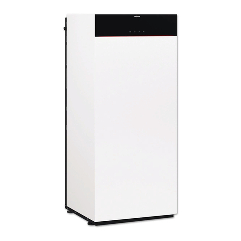
Viessmann VITOCROSSAL 300 Instruction manual

Other manuals for VITOCROSSAL 300

28

This manual suits for next models

8

Other Viessmann Boiler manuals

Viessmann VITOLADENS 300-W Quick guide

Viessmann

Viessmann VITOLADENS 300-W Quick guide

Viessmann VITOLIGNO 300-S User manual

Viessmann

Viessmann VITOLIGNO 300-S User manual

Viessmann FB2B Quick guide

Viessmann

Viessmann FB2B Quick guide

Viessmann VITODENSd 100-W Instruction manual

Viessmann

Viessmann VITODENSd 100-W Instruction manual

Viessmann VITOCELL 300B User manual

Viessmann

Viessmann VITOCELL 300B User manual

Viessmann VITODENS 200 WB2B User manual

Viessmann

Viessmann VITODENS 200 WB2B User manual

Viessmann Vitogas 050 ECD Series Supplement

Viessmann

Viessmann Vitogas 050 ECD Series Supplement

Viessmann Vitoligno 250-S User manual

Viessmann

Viessmann Vitoligno 250-S User manual

Viessmann B2HB 45 User manual

Viessmann

Viessmann B2HB 45 User manual

Viessmann WB2B 45 User manual

Viessmann

Viessmann WB2B 45 User manual

Viessmann Vitocrossal 300 CA3 2.5 Quick guide

Viessmann

Viessmann Vitocrossal 300 CA3 2.5 Quick guide

Viessmann VITOCELL 300-H User manual

Viessmann

Viessmann VITOCELL 300-H User manual

Viessmann VITOCELL 100-U User manual

Viessmann

Viessmann VITOCELL 100-U User manual

Viessmann Vitodens 200 WB2 11-44 User manual

Viessmann

Viessmann Vitodens 200 WB2 11-44 User manual

Viessmann VITOCROSSAL 300 Operating instructions

Viessmann

Viessmann VITOCROSSAL 300 Operating instructions

Viessmann Vitodens 300 User manual

Viessmann

Viessmann Vitodens 300 User manual

Viessmann VITOCROSSAL 300 Operating instructions

Viessmann

Viessmann VITOCROSSAL 300 Operating instructions

Viessmann Vitodens 200-W System Operating instructions

Viessmann

Viessmann Vitodens 200-W System Operating instructions

Viessmann Vitorond 100 Quick guide

Viessmann

Viessmann Vitorond 100 Quick guide

Viessmann VITODENS 100-W P25 User manual

Viessmann

Viessmann VITODENS 100-W P25 User manual

Viessmann Vitodens 200-W System Quick guide

Viessmann

Viessmann Vitodens 200-W System Quick guide

Viessmann VR1 22 Quick guide

Viessmann

Viessmann VR1 22 Quick guide

Viessmann VITOFLEX 300-UF Installation and user guide

Viessmann

Viessmann VITOFLEX 300-UF Installation and user guide

Viessmann VITORONDENS 200-T Operating instructions
Viessmann

Viessmann VITORONDENS 200-T Operating instructions

Popular Boiler manuals by other brands

IDEAL IMAX XTRA EL 320 user guide

IDEAL

IDEAL IMAX XTRA EL 320 user guide

UTICA BOILERS BC3D Installation, operation & maintenance manual

UTICA BOILERS

UTICA BOILERS BC3D Installation, operation & maintenance manual

Lochinvar SOLUTION 260000 Installation & service manual

Lochinvar

Lochinvar SOLUTION 260000 Installation & service manual

Weil-McLain EG 6 Series manual

Weil-McLain

Weil-McLain EG 6 Series manual

RBI LCD Series Installation & operation manual

RBI

RBI LCD Series Installation & operation manual

Baxi MainEco Combi 28 Installation and service manual

Baxi

Baxi MainEco Combi 28 Installation and service manual

Unical ALKON R 24 Installation and Servicing Manual

Unical

Unical ALKON R 24 Installation and Servicing Manual

Automatic Heating Gasogen Installation and Servicing Manual

Automatic Heating

Automatic Heating Gasogen Installation and Servicing Manual

Alpha GasSaver GS-1 Installation and servicing instructions

Alpha

Alpha GasSaver GS-1 Installation and servicing instructions

Baxi ROCA LAURA PLUS 28/28 Operating, cleaning and maintenance instructions for the user

Baxi

Baxi ROCA LAURA PLUS 28/28 Operating, cleaning and maintenance instructions for the user

Vaillant uniSTOR VIH SW GB 500 BES operating instructions

Vaillant

Vaillant uniSTOR VIH SW GB 500 BES operating instructions

Kärcher HWE 4000 Gas manual

Kärcher

Kärcher HWE 4000 Gas manual

Radijator BIO max 23.1 instruction manual

Radijator

Radijator BIO max 23.1 instruction manual

Granby BKC Installation, operation and maintenance manual

Granby

Granby BKC Installation, operation and maintenance manual

Brunner BSV 20 Instructions for use

Brunner

Brunner BSV 20 Instructions for use

Potterton 50e Installation and Servicing Manual

Potterton

Potterton 50e Installation and Servicing Manual

UTICA BOILERS TriFire Assembly instructions

UTICA BOILERS

UTICA BOILERS TriFire Assembly instructions

ECR International UB90-125 Installation, operation & maintenance manual

ECR International

ECR International UB90-125 Installation, operation & maintenance manual

manuals.online logo
manuals.online logoBrands
  • About & Mission
  • Contact us
  • Privacy Policy
  • Terms and Conditions

Copyright 2025 Manuals.Online. All Rights Reserved.

V
VV
VI
II
IT
TT
TO
OO
OC
CC
CR
RR
RO
OO
OS
SS
SS
SS
SA
AA
AL
LL
L 3
33
30
00
00
00
0
Gas-fired condensing boiler
638 to 3361 MBH / 187 to 985 kW
Product may not be exactly as illustrated.
Vitocrossal 300 CT3 boiler with
Vitotronic NR2 control
Technical Data Manual
Model Nos. and pricing: see Price List
Vitocrossal 300
CT3 Series
High efficiency, gas-fired condensing oiler
for natural gas or liquid propane
with vertical Inox-Crossal heat exchanger surfaces
of corrosion-resistant stainless steel.
For operation without low limit on boiler return water
temperature.
For closed loop hot water heating systems with maximum
supply water temperatures of 210°F / 99°C for a
maximum operating pressure of 30 psig.
Heating input: 638 to 3361 MBH
187 to 985 kW
5
2
8
5
8
7
1
v
1
.
9
1
1
/
2
0
1
2
Product Information
2VITOCROSSAL 300, CT3
VITOCROSSAL 300
The enefits at a glance:
HVertical Inox-Crossal heating surfaces for
high operational reliability and long service
life.
– Easy dispersal of condensate through
vertical gas flues; therefore no
concentration of condensate.
– Increased self-cleaning effect through
smooth stainless steel surfaces.
HHighly efficient heat transfer and high
condensation rate through
– heat exchanger surfaces which intensely
turbulate the flue gas flow
– boiler water and hot gases flowing in
counterflow.
HEfficiency up to 98.3 % through intensive
condensation. The flue gas temperature is
only approx. 9 - 27°F / 5 - 15°C above
boiler return temperature.
HClean combustion – through perfect match
of burner and boiler low combustion
chamber loading and straight-through
combustion chamber.
HTwo return connections – providing
separate connection for heating circuits
with lower return temperature. This leads
to increased hot gas condensation.
HEasy handling in boiler rooms through
particularly low build height and weight;
also available in sections.
HEasy installation and elimination of wiring
mistakes with Viessmann prewired plug-in
system.
HHeating boiler heating system control
domestic hot water storage tank and all
other Viessmann system technology
components are co-ordinated to one
another. All components are
design-matched for quick installation.
HEconomical and safe heating system
operation through Vitotronic digital control
system with communication capability.
Tailored to every need covering all known
control strategies and applications.
Standard LON BUS for complete
integration into building management
systems.
Possible integration into the Vitocontrol
control panel.
5
2
8
5
8
7
1
v
1
.
9
Vitocrossal 300 boiler efficiency dependent on system
heating water return temperatures and load conditions
Product Information
Cut-Away Section
Product may not be exactly as illustrated
VITOCROSSAL 300, CT3 3
Two return Stainless steel Stainless steel Wide diameter Highly effective, 4”
connections arranged Inox-Crossal heat water-cooled water walls – proper wrap-around insulation
a ove each other exchanger surfaces com ustion cham er gravity circulation
5
2
8
5
8
7
1
v
1
.
9
4VITOCROSSAL 300, CT3
Technical data
Boiler model CT3- 17 22 28 37 46 57 72 89
Input MBH 638 846 1071 1389 1726 2160 2702 3361
kW 187 248 314 407 506 633 792 985
Output
*1
MBH 626 827 1044 1350 1675 2094 2616 3252
kW 183 242 306 396 491 614 767 953
Com ustion efficiency
Thermal efficiency
%
%
98.3
98.1
97.8
97.7
97.4
97.4
97.2
97.2
97.1
97.1
96.9
96.9
96.8
96.8
96.7
96.7
Boiler output at
80/60° C - 176/140° F
70/50° C - 158/122° F
40/30° C - 104/86° F
MBH
kW
MBH
kW
MBH
kW
554
162.3
576
168.7
607
177.8
734
215.3
763
223.7
805
235.8
930
272.6
966
283.2
1019
298.6
1206
353.3
1253
367.1
1321
387.1
1502
440.2
1561
457.4
1645
482.2
1879
550.7
1953
572.2
2059
603.2
2351
689.0
2443
716.0
2575
754.8
2924
857.0
3038
890.4
3203
938.7
Boiler stand y loss
at maximum input
80/60° C - 176/140° F
70/50° C - 158/122° F
40/30° C - 104/86° F
Btu/h
W
%
Btu/h
W
%
Btu/h
W
%
2566
752
0.40
2139
627
0.34
856
251
0.13
2818
826
0.33
2347
688
0.28
938
275
0.11
3064
898
0.29
2552
748
0.24
1020
299
0.10
3583
1050
0.26
3047
893
0.22
1143
335
0.08
4299
1260
0.25
3583
1050
0.21
1433
420
0.08
5240
1536
0.24
4367
1280
0.20
1747
512
0.08
5753
1686
0.21
4794
1405
0.18
1918
562
0.07
6633
1944
0.20
5753
1686
0.17
2211
648
0.07
Dimensions - oiler as shipped
(p)Length (door removed)
(q)Width 1 (max. shell width)
(r)Height
*2
(max.)
Overall dimensions
(s)Overall length
(t)Overall width (incl. insulation
and control)
(u)Overall height (to top of
installed
header)
(v)Width (upper with jacketing)
(w)Width (lower with jacketing)
Boiler support frame
(x)Length
(y)Width
(z)Height
inches
mm
inches
mm
inches
mm
inches
mm
inches
mm
inches
mm
inches
mm
inches
mm
inches
mm
inches
mm
inches
mm
59¾
1516
27
684
69
7
/
8
1773
64¼
1636
40
1016
79
7
/
8
2027
34½
874
31½
798
35¼
895
27¼
690
2¾
70
62¾
1594
27
684
71d
1808
67½
1714
40
1016
81d
2062
34½
874
31½
798
38e
975
27¼
690
2¾
70
66
1675
27
684
71¼
1811
70½
1795
40
1016
81¼
2065
34½
874
31½
798
41½
1055
27¼
690
2¾
70
69
1751
31½
800
79f
2023
73½
1871
44½
1132
93
5
/
16
2370
39
990
36
914
47¼
1200
32½
800
2¾
70
72¼
1829
31½
800
79f
2023
76¾
1949
44½
1132
93
5
/
16
2370
39
990
36
914
50
1270
32½
800
2¾
70
78¼
1985
31¼
800
79f
2023
83
2105
44½
1132
93
5
/
16
2370
39
990
36
914
56¼
1430
32½
800
2¾
70
82½
2095
37½
951
88
2235
85½
2172
49
1249
101¾
2585
45d
1147
39
990
56¼
1430
35½
900
2¾
70
90
2289
37½
951
88
2235
93¼
2366
49
1249
101¾
2585
45d
1147
39
990
64d
1630
35½
900
2¾
70
Weight
boiler shell
front cone (includes combustion
chamber door)
Overall weight
complete with insulation and
control (less burner)
lbs
kg
lbs
kg
lbs
kg
1012
459
413
187
1228
557
1114
505
413
187
1352
613
1202
545
413
187
1455
660
1671
758
490
222
1962
890
1759
798
490
222
2064
936
1995
905
490
222
2322
1053
2706
1230
600
273
3014
1370
3014
1370
600
273
3344
1520
*1
Output ratings are based on the IBR BTS-2 “method to determine efficiency of commercial space heating boilers”.
*2
Boilers CT3-17, 22, 28 are shipped with header attached (u) - see overall height dimensions and add 4” (1 mm) for the wood blocks
as per transportation height.
Technical Data
5
2
8
5
8
7
1
v
1
.
9
Technical Data
VITOCROSSAL 300, CT3 5
Technical data (continued)
Boiler model CT3- 17 22 28 37 46 57 72 89
Boiler water content USG 71.3 78.2 87.2 129.5 140.8 150.6 199.2 221.9
ltr 270 296 330 490 533 570 754 840
Heat exchanger surface
water-cooled ft.
2
85.0 107.6 123.8 176.5 200.2 245.4 316.5 383.2
m
2
7.9 10.0 11.5 16.4 18.6 22.8 29.4 35.6
Max. operating temperature °F 210
°C 99
Max. operating pressure psig 30
kpa 207
Flue gas resistance “w.c. 0.40 0.56 0.64 0.80 0.88 1.08 1.20 1.32
Pa 100 140 160 200 220 270 300 330
Boiler connections
boiler supply (BS)
& return (BR1)
Boiler return (BR2)*
3
Safety supply
Boiler drain
Condensate drain
inches
mm
inches
mm
inches
mm
inches
inches
2½
65
2
50
1¼
32
1
½
2½
65
2
50
1¼
32
1
½
3
80
2
50
2
51
1
½
4
100
3
75
2
50
1
½
4
100
3
75
2
50
1
½
4
100
3
75
2
50
1
½
5
125
4
100
2½
65
1
½
5
125
4
100
2½
65
1
½
Vent pipe
internal Ø inches
mm
8
201
8
201
8
201
10
251
10
251
10
251
12
301
12
301
Flue gas values*
4
Temperature (at a return
temperature of 86°F / 30°C)
- at rated input
- at partial load
Temperature (at a return
temperature of 140°F / 60°C)
Mass flow rate (of flue gas)
Gas volume of combustion
chamber and heat exchanger
°F
°C
°F
°C
°F
°C
lbs/h
kg/h
ft.
3
m
3
113
45
104
40
167
75
704
320
8.83
0.250
113
45
104
40
167
75
928
422
9.92
0.281
113
45
104
40
167
75
1179
536
12.00
0.340
113
45
104
40
167
75
1531
696
15.90
0.450
113
45
104
40
167
75
1903
865
18.40
0.521
113
45
104
40
167
75
2380
1082
21.54
0.610
113
45
104
40
167
75
2979
1354
40.61
1.150
113
45
104
40
167
75
3705
1684
42.73
1.210
Pressure
at boiler flue outlet
- at partial input
- at maximum input
Pa
Pa
±0
-3
-3
-4
±0
-2
-5
±0
±0
±0
±0
±0
±0
±0
±0
±0
*3
Boiler has two return connections - the heating return with the lower temperature should be connected to the boiler return BR1.
*4
Values for calculating the size of the flue system based on 1 % CO
2
for natural gas.
Flue gas temperatures measured as gross values at 68ºF / 2 ºC combustion air temperature.
The details for partial load refer to an output of 3 % of rated input. Calculate the flue gas mass flow rate accordingly when the
partial load differs from that stated above (subject to the burner mode).
"
For information regarding other Viessmann System Technology componentry, please reference documentation of respective product.
5
2
8
5
8
7
1
v
1
.
9
Technical Data
6VITOCROSSAL 300, CT3
Note: - Dimensions p through z shown above are listed on page 4.
- Minimum shipping dimensions: use “o” in the table below, and height, width q or y (which ever is larger) in the diagram above.
Dimensions
Boiler model CT3- 17 22 28 37 46 57 72 89
a
b
c
d
e
f
g
h
j
k
l
m
n
o(split boiler
shipping length)
Recomended
Boiler pad
inches
mm
inches
mm
inches
mm
inches
mm
inches
mm
inches
mm
inches
mm
inches
mm
inches
mm
inches
mm
inches
mm
inches
mm
inches
mm
inches
mm
inches (L)
mm
inches (W)
mm
inches (H)
mm
28¾
715
11¾
298
20½
518
62¾
1594
76e
1940
7
177
9
227
31½
802
7
180
10
257
51¼
1299
7½
194
5½
141
37
942
47
1200
35
889
4
100
28¾
715
11¾
298
20½
518
64¼
1631
78
1980
7
177
9
227
33½
852
7
180
10
257
53
1349
7½
194
5½
141
40
1020
50
1270
35
889
4
100
28¾
715
11¾
298
20½
523
64¾
1644
78f
1996
7
177
9
221
33½
852
7
180
10
257
53
1349
7½
194
4¾
121
42½
1081
53
1346
35
889
4
100
29¾
751
12¾
325
22¾
577
73
1854
88¾
2254
9½
200
8
241
36¼
921
7d
182
11¼
284
59
1500
7½
190
3
79
42½
1079
59
1500
39
990
4
100
29¾
751
12¾
325
22¾
577
73
1854
88¾
2254
9½
200
8
241
36¼
921
7d
182
11¼
284
59
1500
7½
190
3
79
45½
1157
62
1573
39
990
4
100
29¾
751
12¾
325
22¾
577
73
1854
88¾
2254
9½
200
8
241
36¼
921
7d
182
11¼
284
59
1500
7½
190
3
79
51½
1313
68
1727
39
990
4
100
29¾
755
14¼
363
25¼
644
80½
2043
97
2463
10
250
11
280
38
965
8
7
/
8
225
14
360
63¾
1621
7¾
197
2½
65
55¼
1405
76
1930
43
1092
4
100
29¾
755
14¼
363
25¼
644
80½
2043
97
2463
10
250
11
280
38
965
8
7
/
8
225
14
360
63¾
1621
7¾
197
2½
65
63
1599
76
1930
43
1092
4
100
*1
The minimum combustion head length of 5½” / 14 mm must be maintained. When a burner with a shorter combustion head is used,
all functions including combustion results must be verified. The maximum combustion head length must also be observed so that the
burner on the hinged combustion chamber door can swing into service position. Radius of door hinge to outside combustion head:
18¾” / 476 mm.
5
2
8
5
8
7
1
v
1
.
9
Legend
V Vent pipe connection
SH Female connection R ½” for air vent
and pressure gage
D Drain
CD Condensate drain
BR 1 Boiler return 1
BR 2 Boiler return 2
BTS Boiler temperature sensor
BD Boiler door with burner connecting
flange
BS Boiler supply
IO Inspection opening
SS Safety supply for pressure relief
valve
OP Observation port (boiler from
CT3-17 - 28: offset by 90º )
Technical Data
VITOCROSSAL 300, CT3 7
Recommended minimum service clearances
Boiler
Burner
To enable convenient installation and
maintenance observe the stated clearance
dimensions. Maintain the minimum
clearances where space is tight. In the
delivered condition the boiler door opens to
the right. You can relocate the hinge bolts
so that the door can open to the left.
Mechanical room
HDo not operate when air is polluted with
halogenated hydrocarbons (e.g. as in
aerosols paints solvents and cleaning
agents)
HPrevent very dusty conditions
HPrevent high levels of humidity
HPrevent freezing and ensure good
ventilation
Boiler model CT3- 17 22 28 37 46 57 72 89
v
w
x
y
z
inches
mm
inches
mm
inches
mm
inches
mm
inches
mm
28
711
62¾
1593
36½
930
40
1012
41¼
1048
28
711
65¾
1671
39¼
1000
40
1012
41¼
1048
28
711
69
1752
43¼
1100
40
1012
41¼
1048
35
889
72
1828
59
1500
44½
1128
45¼
1149
35
889
75
1906
59
1500
44½
1128
45¼
1149
39
991
81¼
2062
59
1500
44½
1128
45¼
1149
45
1143
85½
2172
59
1500
49
1243
48
1219
45
1143
93¼
2366
59
1500
49
1243
48
1219
M
inimum clearances to com usti les
Boiler model CT3- 17 22 28 37 46 57 72 89
Top 6” / 150 mm
Sides 6” / 150 mm
Flue As per vent manufacturer’s specifications
Front 6” / 150 mm
Floor combustible
5
2
8
5
8
7
1
v
1
.
9
Length of
burner
y
wx
v
z
500
mm
19¾”
500
mm
19¾”
200 mm
8”
Technical Data
8VITOCROSSAL 300, CT3
Pressure drop (primary circuit)
The Vitocrossal 300 boiler is only suitable for heating systems with
pumped heating water.
Legend:
CT3-17 to -22
CT3-28
CT3-37 to -57
CT3-72 to -89
Recommended Flow Rates
Boiler model CT3- 17 22 28 37 46 57 72 89
20°F ∆t
40°F ∆t
11°C ∆t
22°C ∆t
GPM
GPM
ltrs/s
ltrs/s
61
31
3.9
2.0
81
41
5.1
2.6
103
52
6.5
3.3
134
67
8.5
4.2
166
83
10.5
5.3
208
104
13.2
6.6
260
130
16.5
8.2
323
162
20.4
10.3
"
∆t= temperature difference
"
This boiler does not require a flow switch.
5
2
8
5
8
7
1
v
1
.
9
60
80
70
8
7
1
2
3
4
5
6
10
20
30
40
50
60
100
2 3 4 5 6 7 8 10 20 30 40 50
Flow rate
Pressure drop
40
20
16
”w.c.
8.8 13.2
17.6
22
26.4
44 88 132 176 GPM
220
264
308
352
mbar
m
3/
h
70 80
32
28
24
12
8
3.2
4
2.8
2.4
2
1.6
1.2
0.8
0.4
Standard Equipment
Boiler Control Alternatives
VITOCROSSAL 300, CT3 9
Standard Equipment
Note:
Boiler controls and burners are purchased
separately. Please see Price List for details.
Boiler body and fitted boiler door with burner
plate fitted clean-out cover and fitted
mating flanges incl. gaskets on all
connectors with flue gas collector.
For tight spaces Vitocrossal 300 can also be
delivered in sections. The front of the
combustion chamber can be removed on
site be brought into the boiler room and
refitted there.
H2 cartons with insulation
H1 carton containing boiler control unit
H1 water connection pipe fitted to the
boiler skid (from CT3-37)
H1 burner plate pack
H1 carton of installation fitting
Standard equipment of installation fittings
includes:
Hlow water cut-off
Hsafety header (c/w 30 psig pressure relief
valve air vent and pressure gage)
Hdrain valve
Hproduct documentation
Ensure
specific regional, provincial, or
state requirements, such as gas train and
additional safety control requirements
etc., are known efore the product order
is placed, to determine proper urner
selection and pricing.
Boiler Control Alternatives
For single oiler systems:
Hwithout Vitocontrol control panel
Vitotronic 100 (type GC1)
for constant boiler water temperature or
outdoor reset mode in conjunction with an
external control unit (BMS).
Vitotronic 300 (type GW2)
for modulating boiler water temperature
with mixing valve control for a maximum
of two heating circuits with mixing valve.
Hwith Vitocontrol control panel
Vitotronic 100 (type GC1)
and
Vitocontrol-S, CT3 control panel
with Vitotronic 333 for outdoor reset
mode and mixing valve control for a
maximum of 2 heating circuits with mixing
valve and additional Vitotronic 050
type HK1S or HK3S for 1 or up to 3
heating circuits with mixing valve.
For multi- oiler system (up to
4 boilers):
Hwithout Vitocontrol control panel
Vitotronic 100 (type GC1) and LON module
for modulating boiler water temperature in
conjunction with an extrnal control unit
(BMS).
Hwith Vitocontrol control panel
Vitotronic 100 (type GC1) and LON module
for modulating boiler water temperature
for each boiler of the multi-boiler system
and
Vitocontrol-S, CT3 control panel
with Vitotronic 333 for multi-boiler system
outdoor reset mode and mixing valve
control for a maximum of 2 heating circuits
with mixing valve and additional
Vitotronic 050 type HK1S or HK3S for 1 or
up to 3 heating circuits with mixing valve.
For single- or multiple- oiler
installations:
Custom control panels
Custom control panels for residential or
commercial applications are designed and
manufactured by Viessmann to suit any
customer’s specific requirements. Custom
control panels can have features such as
pool heating hot tub heating snow melting
telephone tie-in integration with Building
Management Systems as well as several
other functions. Please inquire.
5
2
8
5
8
7
1
v
1
.
9
IMPORTANT
System Design Considerations
10 VITOCROSSAL 300, CT3
System Design Considerations
Venting
The Vitocrossal 300 boiler is a category IV
positive pressure condensing boiler. Each
boiler must be vented individually.
Depending on the boiler return water
temperature the flue gases in the boiler are
cooled down into the condensation or dew
point area of the flue gases. Where they exit
the boiler they reach a relative moisture of
100%. The flue gas temperature is between
9°F and 27°F (5°C and 15°C) higher than
the boiler return water temperature.
Therefore depending on the connected
heating system the flue gas temperature
can be beween 77°F / 25°C and 200°F /
93°C. Due to the low flue gas temperature
and the resulting minute updraft conditions
as well as the additional condensation of the
flue gases in the venting system the vent
system must be properly designed and
suitable materials must be selected. The
chimney must be gas and water tight.
Use an AL29-4C® special stainless steel
venting system (UL/ULC/CSA listed for
category IV) for vertical venting of the
Vitocrossal 300 boiler.
The following manufacturers may be
contacted for suitable stainless steel
chimneys:
ProTech Systems Inc.
26 Gansevoort Street
Albany NY 12202
Tel.: (518) 463-7284
Fax: (518) 463-5271
Toll free: 1-800-766-3473
Selkirk Metal estos
Selkirk Canada Corporation - head office
375 Green Road
Stoney Creek ON L8E 4A5
Tel.: (905) 662-6600
Fax: (905) 662-5352
Toll free: 1-800-263-9308
Security Chimneys
Division of Security Chimneys Ltd.
2125 Monterey
Laval PQ H7L 3T6
Tel.: (450) 973-9999
Fax: (450) 973-2222
Toll free: 1-800-667-3387
Van-Packer Co. Inc.
302 Mill Street
PO Box 307
Buda IL 61314
Tel.: (309) 895-2311
Fax: (309) 895-3891
Toll free: 1-888-877-8225
Exhausto CASV/CASI
Mechanical Draft System
Wesmech Technical Sales
50 Ronson Drive Suite 160
Toronto ON M9W 1B3
Tel.: (416) 251-8990
Fax: (416) 251-8900
Toll free: 1-800-613-3789
Condensate and its disposal
During the operation of the boiler the
amount of condensate to be expected can
be read from the diagram below.
The values given are approximate amounts
occurring under practical conditions. Not
included in the diagram is the amount of
condensate occurring in the vent pipe and
chimney system. The condensate from the
chimney system can be collected together
with the condensate from the heating boiler
and be disposed of into a floor drain. The
condensate will be between 3 and 4 on the
pH scale. If local building requirements
demand neutralizing the condensate before
disposal contact Viessmann Manufacturing
Company Inc. for a correctly sized
neutralization tank. The treated condensate
will show pH values of between 6.5 and 9
and can then be disposed of into the waste
water system.
5
2
8
5
8
7
1
v
1
.
9
Do not use PVC or CPVC material for
venting the Vitocrossal 300 oiler.
CAUTION
Flue gas temperature gross
Boiler water return temperature
Amount of condensate
Note: The “amount of condensate” and the “flue gas temperature
gross” graphs are independent of each other.