Viessmann 21751 User manual

Gebrauchsanleitung
Manual
Ideale Ergänzung: Sound
Noch mehr Leben bringen die überall einsetzbaren Viessmann
Soundmodule passend zu unseren Themenwelten und Modellen!
Mehr Infos im Internet:
www.viessmann-modell.de
DC
=
DCC
AC
~
MM Diorama
Digital-Funktionsmodell
mit Beleuchtung / Bewegung
Digital Functional Model
with lighting / movement
21751, 29751, 24071, 49817,
5131, 5132, 5832
1. Wichtige Hinweise ...................................... 2
2. Einführung / Eigenschaften ........................ 2
3. Einbau ....................................................... 3
4. Anschluss ................................................... 3
5 Betrieb ........................................................ 4
6. Fehlersuche & Abhilfe ................................ 8
7. Technische Daten ...................................... 8
1. Important Information ................................. 2
2. Introduction / Properties ............................. 2
3. Mounting .................................................... 3
4. Connections ............................................... 3
5. Operation ................................................... 4
6. Troubleshooting ......................................... 8
7. Technical Data ........................................... 8
49817
21751
5131

2
DE EN
Märklin ist ein eingetragenes Warenzeichen der / is a registered
trademark of Gebr. Märklin & Cie GmbH, Göppingen. TRIX ist ein eingetragenes Warenzeichen der / is a registered
trademark of Gebr. Märklin & Cie GmbH, Göppingen.
1. Wichtige Hinweise
Vor Gebrauch die Sicherheitshinweise und Anlei-
tung genau lesen und beachten! Anleitung aufbe-
wahren. Sie ist Teil des Produktes.
Sicherer Betrieb
Vorsicht: Verletzungsgefahr! Aufgrund der
detaillierten Abbildung des Originals bzw.
der vorgesehenen Verwendung kann das
Produkt Spitzen, Kanten und abbruchge-
fährdete Teile aufweisen. Das Produkt ge-
hört aus diesem Grund nicht in die Hände
von Kindern!
Vorsicht: Stromschlaggefahr! Die An-
schlussdrähte niemals in eine Steckdose
einführen! Verwendetes Versorgungsge-
rät (Transformator, Netzteil) regelmäßig
auf Schäden an Kabeln, Stecker, Gehäuse
usw. prüfen. Bei Schäden am Versorgungs-
gerät dieses keinesfalls benutzen!
Das Produkt richtig verwenden
Das Produkt darf ausschließlich dieser Anleitung
gemäß verwendet werden.
Dieses Funktionsmodell ist bestimmt
► zumEinbauinModelleisenbahnanlagen
und Dioramen
► zumAnschlussaneinenzugelassenen
Modellbahntransformator bzw. an einer
damit versorgten elektrischen Steuerung
► zumBetriebintrockenenRäumen.
Jeder darüber hinausgehende Gebrauch gilt als
nicht bestimmungsgemäß. Für daraus resultieren-
de Schäden haftet der Hersteller nicht.
Achtung: Die Antriebseinheit im Zylinder
sowiedieinderZuleitungbendlicheelek-
tronische Baugruppe dürfen nicht geöffnet,
beschädigt, oder mit Feuchtigkeit im Ver-
bindung gebracht werden. Diese sind für
den einwandfreien Betrieb erforderlich.
2. Einführung / Eigenschaften
Die Funktionsmodelle der Serie eMotion – Be-
wegte Welt sorgen für Leben auf der Modelleisen-
bahn. Das speziell entwickelte Funktionsmodul ist
mit einer elektronischen Steuerung ausgerüstet,
die realistische Licht- oder Bewegungseffekte er-
zeugt. Antrieb und Steuerung sind fest mit dem
Modell verbunden.
1. Important Information
Read and follow these safety precautions and in-
structions carefully before use! Keep this manual.
It is part of the product.
Safe operation
Caution: Risk of injury! Due to the detailed
reproduction of the original and the intend-
ed use, this product can have peaks, edges
and breakable parts. For that reason this
product is not for children.
Warning: Electrical hazard! Never put the
connecting wires into a power socket! Reg-
ularly examine the transformer for damage
to the cord, plug, case etc. In case of any
damage, do not use the transformer!
Using the product for its correct
purpose
This product must only be used as specied in
this manual.
This model is intended
► for installation in model railroad layouts
and dioramas
► for connection to an authorized model
railroad transformer or an electrical con-
trol system connected to one
► for operation in a dry area.
Using the product for any other purpose is not ap-
proved and is considered incorrect. The manufac-
turer cannot be held responsible for any damage
resulting from the improper use of this product.
Caution: The drive unit in the plastic cylin-
der and the electronic control unit connect-
ed to the model must not be opened, dam-
aged, or brought in contact with moisture.
Both components are essential for safe op-
eration of the model.
2. Introduction
The functional models of the eMotion series bring
life to your model train layout. The drive unit con-
tains a controller, which generates realistic lighting
effects or movements. Drive and control unit are
xed to the model.

3
90°
Fig. 1
Abb. 1
Digitaldecoder integriert
Dieses Funktionsmodell ist mit einem integrierten
Digitaldecoder ausgestattet. Die Steuerung ist mit
jeder handelsüblichen Digitalzentrale der Formate
DCC oder MM möglich.
Diorama-Modus
Das Modell ist mit einem zufällig gesteuerten au-
tomatischen Betriebsprogramm ausgestattet. Die-
ser sogenannte Diorama-Modus dauert etwa 30
Minuten. Nach Ablauf des Programms schaltet
sich das Modell aus und wartet auf neue Steuer-
befehle.
Achtung: Bruchgefahr! Modell stets vorsichtig am
Gehäuseanfassen,dadieligranenTeiledesMo-
dells sonst abbrechen könnten.
3. Einbau
1. Bohren Sie an der Montagestelle ein Loch
(Durchmesser 12 mm).
2. Führen Sie die Anschlusskabel von oben durch
das Loch.
3. Schieben Sie den Antrieb so weit in die Boh-
rung,bisermitseinemoberenRandauiegt.
4. Befestigen Sie das Modell mit dem beilie-
genden Befestigungsring.
Schieben Sie dazu den Ring auf dem Antrieb
so weit nach oben, bis das Modell fest gehalten
wird. Drehen Sie den Ring um 90°, um ihn zu
arretieren.
4. Anschluss
Konventioneller Betrieb: Die Betriebsspannung
des Modells beträgt 14 – 16 V = / ~.
Digitalbetrieb: Geeignet für Digitalzentralen der
Formate MM und / oder DCC.
Integrated digital decoder
This functional model is equipped with an integrat-
ed digital decoder. It can be controlled by every
commercial digital command station of the proto-
cols DCC and MM.
Diorama mode
This model is equipped with an automatic random
operation program. This diorama mode runs for
approx. 30 minutes. At the end of the program the
model stops and waits for new input.
Notice: If you have to unmount the model, care-
fully push the drive unit upward, otherwise the
delicate parts of the model may break.
3. Mounting
1. Drill a hole of 12 mm diameter at the mount-
ing place.
2. Insert the connection wires into the hole from
the top.
3. Insert the drive unit.
4. Attach the model to the baseboard with the en-
closed ring. Put the ring over the cables and
the drive unit (Fig. 1).
Turn the ring 90° to lock it.
Connection
Conventional operation: The power supply
should be between 14 and 16 V AC or DC.
Digital operation: Works with digital command
stations with the protocols DCC and MM.
12 mm

4
Sekundär
0-10-16 V~
16 V
Primär
230 V~
Gefertigt nach
VDE 0570
EN 61558
Lichttransformator
5200
Nur für trockene Räume
Primär 230 V 50 - 60 Hz
Sekundär max. 3,25 A52 VA ta 25°CIP 40
10 V
0 V
Universal Tasten - Stellpult
5547
Viessmann
gelb
braun
z. B. 5200
z. B. 5547
grün
Antriebseinheit
Elektronik
braun 2x blau
rot
brown
e. g. 5200
yellow
e. g. 5547
/ green
drive unit
electronic unit
/ brown / blue
/ red
Fig. 2
Abb. 2
Sekundär
0-10-16 V~
16 V
Primär
230 V~
Gefertigt nach
VDE 0570
EN 61558
Lichttransformator
5200
Nur für trockene Räume
Primär 230 V 50- 60 Hz
Sekundär max. 3,25 A52 VA ta25°CIP 40
10 V
0 V
viessmann 5550
Universal Ein-Aus-Umschalter
gelb
braun
z. B. 5200
z. B. 5550
grün
Antriebseinheit
Elektronik
braun 2x blau
rot
brown
e. g. 5200
yellow
e. g. 5550
/ green
drive unit
electronic unit
/ brown / blue
/ red
Schalter-Betrieb
Switch Operation
Achtung:
Alle Anschluss- und Montagearbeiten dür-
fen nur bei abgeschalteter Betriebsspan-
nung durchgeführt werden!
Verwenden Sie nur nach VDE / EN-gefer-
tigte Modellbahntransformatoren oder Digi-
talzentralen der Protokolle DCC / MM!
Schließen Sie das Modell gemäß der Abbildungen
auf Seite 4 bzw. 5 an.
5. Betrieb
Dieses eMotion Funktionsmodell ist für konventi-
onellen sowie digitalen Betrieb ausgelegt. Der in-
tegrierte Digitaldecoder für die Formate DCC und
MM (Märklin/Motorola) ermöglicht die Steuerung
über eine geeignete Digitalzentrale (z. B. Viess-
mann Commander).
Caution:
Installation and electrical wiring may only
be carried out while the power supply is
switched off.
Only use transformers compliant with VDE
/ EN standards or digital command stations
with DCC / MM.
Connect the model as shown in gures 2 and 3 on
pages 4 and 5.
5. Operation
This eMotion functional model is designated for
either conventional or digital operation. The inte-
grated digital decoder for the protocols DCC and
MM (Maerklin Motorola) enables the user to con-
trol the model via a digital command control sta-
tion (e. g. Viessmann Commander).

5
MM / DCC
49817
gelb
braun
Digitalzentrale
braun
Elektronik
/ yellow
brown
Digital Command Station
brown
electronic unit
Fig. 3
Abb. 3
Funktionen konventionell
Für den Betrieb benötigen Sie ein Tastenstellpult
(s. Abb. 2) oder ein Schalterpult (z. B. Viessmann
5550). Bei Verwendung des Schalters ist aus-
schließlich der Betrieb im Diorama-Modus möglich
(s. kleine Abb. 2 „Schalter-Betrieb“).
Betrieb mit Tastenstellpult
Bewegung automatisch:
►GewünschteTastekurzdrücken(<1,2Sek.).
Das Modell bewegt sich bis zur jeweiligen Endpo-
sition. Kurzes Drücken der Taste für die Gegen-
richtung stoppt die Bewegung sofort.
Bewegung manuell:
►GewünschteTastesolangegedrückthalten,
wie die Bewegung dauern soll (> 1,2 Sek.).
Die Bewegung stoppt sobald die Taste losgelas-
sen wird.
Bewegungsrichtung:
grün = Uhrzeigersinn (rechts / hoch)
green = clockwise (right / up)
Direction of movement:
rot = Gegenuhrzeigersinn (links / runter)
red = counterclockwise (left / down)
Functions (conventional)
For operation of the model a pushbutton panel
(see g. 2) or a switchboard (e. g. Viessmann
5550) is required. When using a switchboard as
in g. 2 (small picture), only operation in diorama
mode is possible. Individual operation and control
is not possible.
Operation with pushbutton panel
Automatic movement:
► Press the desired pushbutton shortly
(< 1,2 sec.).
The model moves until the predened endposition
is reached. Pressing the pushbutton for the oppo-
site direction stops the movement immediately.

6
MM / DCC
49817
Motorola
DCC
gelb Digitalzentrale
braun
Adresse einstellen
grünes Kabel verbinden
rotes Kabel verbinden
rot
grün
Elektronik
/ yellow
Digital Command Station
/ brown
/ Set address
/ connect green cable
/ connect red cable
green
red
electronic unit
Fig. 4
Abb. 4
Diorama-Modus:
Diorama-Modus starten:
►GrünenTaster2xmitkurzerPauseinnerhalb
von ca. 2 Sekunden drücken.
Diorama-Modus beenden:
►Manuell:RotenTastereinmaldrücken.
►Automatisch:DerDiorama-Modusendetbei
Programmende nach ca. 30 Minuten.
Betrieb mit Schalter
Diorama-Modus starten:
►Schaltereinschalten.
Diorama-Modus beenden:
►Manuell:Schalterausschalten.
►Automatisch:DerDiorama-Modusendetbei
Programmende nach ca. 30 Minuten.
Funktionen digital
Digitaladresse:
Legen Sie als erstes eine Digitaldresse fest. Le-
sen Sie dazu den folgenden Abschnitt und beach-
ten Sie Abb. 4. Nach Festlegung der Digitalad-
resse schließen Sie das Modell an, wie in Abb. 3
gezeigt.
Manual movement:
► Press the desired pushbutton and keep it
pressed as long as the model shall move.
The movement stops immediately if the push-
button is released.
Diorama mode:
Start diorama mode:
► Press the green button two times within 2 sec-
onds.
Stop diorama mode:
► Manually: Press the red button one time.
► Automatically: The diorama mode ends at the
end of the program after approx. 30 minutes.
Operation with switch
Start diorama mode:
► Set the switch to position “on”.
Stop diorama mode:
► Manually: Set the switch to position “off”.
► Automatically: The diorama mode ends at the
end of the program after approx. 30 minutes.

7
Adressvergabe:
Zur digitalen Steuerung des Funktionsmodells
müssen Sie diesem zunächst eine Digitaladresse
zuweisen:
1. Digitalsystem ausschalten, z. B. Not-Aus.
Es darf keine Spannung mehr am Gleis anlie-
gen.
2. Nur die jeweilige Steuerleitung (rot markiert =
DCC bzw. grün markiert = MM) und die Strom-
versorgungsleitungen des Funktionsmodells
(braun und gelb, s. Abb. 4) mit dem Gleis ver-
binden.
3. Digitalsystem einschalten.
4. Die zweite Steuerleitung erst jetzt gleichfalls mit
dem Gleis verbinden (s. Abb. 3).
5. Mit der Digitalzentrale für die gewünschte Digi-
taladresse einen Schaltbefehl senden.
Das Modell empfängt den Befehl, registriert die
Adresse im entsprechenden Datenformat und
quittiert dies durch Bewegung.
Damit ist das Modell unter der neuen Adresse be-
triebsbereit. Falls Sie die Adresse künftig ändern
möchten, wiederholen Sie die Prozedur einfach.
Ab Werk ist der Decoder auf die Digitaladresse 1
(DCC) eingestellt.
Digitaler Betrieb:
►GewünschteAdresstasteaufderZentrale
kurz drücken.
Das Modell bewegt sich bis zur jeweiligen Endpo-
sition. Kurzes Drücken der Taste für die Gegen-
richtung stoppt die Bewegung sofort.
Diorama-Modus:
Diorama-Modus starten:
►GrünenTaster/grüneSchaltäche2xmitkur-
zer Pause innerhalb von ca. 2 Sekunden drü-
cken.
Diorama-Modus beenden:
►Manuell:RotenTaster/roteSchaltächeein-
mal drücken.
►Automatisch:DerDiorama-Modusendetbei
Programmende nach ca. 30 Minuten.
Tipp 1:
Bei manchen Digitalzentralen führt ein dauerhaft
gedrückter Taster dazu, dass Weichenschaltbe-
fehle mehrmals nacheinander ausgeführt werden.
Damit lässt sich der Diorama-Modus durch län-
gerenDruckaufdengrünenTaster/Schaltäche
starten.
Functions (digital)
Digital address:
In the digital mode of operation, you use a digital
command station to control the model. Please
read the following chapter to learn how to set a
digital address. After programming an address,
connect the model to your digital layout as shown
in gure 3.
Setup of an address:
To use the model in a digital environment, at rst
you have to assign a digital address:
1. Switch off the digital system (e. g. emergency
off). There must not be any power at the rails.
2. Connect only the needed blue wire (red = DCC,
green = MM) and the power supply wires of the
functional model (brown and yellow, see gure
4) to the rails.
3. Switch on the digital system.
4. Connect the second blue wire to the track sig-
nal (see gure 3).
5. Use the digital command station to send a
switchrequest for the desired address. The
model receives the request, registers the ad-
dress as its own and as a receipt, it moves.
The model is now ready to be used with the new
digital address. If you want to change the address,
you just have to repeat the described procedure.
The default address is DCC 1.
Digital operation:
► Push the desired address key on the digital
command station.
The model moves until the predened end posi-
tion is reached. Pressing the pushbutton for the
opposite direction stops the movement immedi-
ately.
Diorama mode:
Start diorama mode:
► Press the green button / soft key two times in
between 2 seconds with a short break of ap-
prox. 0,5 sec.
Stop diorama mode:
► Manually: Press the red button / soft key one
time.
► Automatically: The diorama mode ends at the
end of the program after approx. 30 minutes.
Hint 1:
Some digital command stations send accessory
orders (for turnouts, signals etc.) continuously if
the pushbutton / soft key is pressed continuously.
If your digital command station does so, you may

Dekoartikel, kein Spielzeug! Nicht geeignet für Kinder unter 14
Jahren! Maßstabsgetreues Modell zur Dekoration einer Modell-
Landschaft. Produkt kann Spitzen, Kanten und abbruchgefährdete
Teile aufweisen. Verletzungsgefahr! Die Anschlussdrähte niemals in
eine Steckdose einführen! Anleitung aufbewahren!
Decoration item, not a toy! Not suitable for children under 14
years! True to scale model for the decoration of a model landscape.
This product can have peaks, edges and breakable parts. Risk of
injury! Never put the connecting wires into a power socket! Keep
these instructions!
Ce produit n’est pas un jouet. C’est un produit décor! Ne
convientpasauxenfantsdemoinsde14ans!Modèleréduitdèle
àl’échellepourladécorationd’unréseau.Leproduitpeutprésen-
terdespointes,desarêtesetdespiècesdétachables.Risquede
blessure!Nejamaisintroduireleslsd’alimentationdansuneprise!
Conservez ce mode d’emploi!
Decoratie artikel, geen speelgoed! Niet geschikt voor kinderen onder 14
jaar! Schaalmodel, bedoeld als decoratie model in een modellandschap.
Kunnen er onderdelen met scherpe punten, zijkanten en ook breekbare
onderdelen aanwezig zijn. Risico op verwonding! De aansluitdraden nooit
in een wandcontactdoos steken! Gebruiksaanwijzing bewaren!
Articolo decorativo, non è un giocattolo! Non adatto a bambini al di
sotto dei 14 anni! Modello in scala per la decorazione di un paesaggio
per modellismo. Il prodotto può presentare punte, spigoli e parti che
potrebbero staccarsi. Pericolo di lesion! Non inserire mai i fili di col-
legamento in una presa! Conservare instruzioni per l’uso!
Artículo para decoración ¡No es un juguete! No recomendado para
menores de 14 años! Este producto es un modelo en miniatura para
decorar un paisaje en una maqueta. Los modelos pueden tener partes
puntiagudas, cantos y piezas filigranas. Riesgo a lesionarse. ¡No intro-
ducirnuncaloshilosdeconexionesenunenchufedelaredeléctrica!
Conserva las instrucciones de servicio!
Modellspielwaren GmbH
8
9/2011 Ko
Stand 01
Sach-Nr. 86870
Made in Europe
Tipp 2:
Bei modernen Digitalzentralen (z. B. Viessmann
Commander, Märklin CS2, ESU EcoS 2) lässt sich
die Schaltdauer eines Schaltimpulses einstellen.
Wenn Ihre Zentrale über diese Möglichkeit ver-
fügt, empfehlen wir die Einstellung der Schaltdau-
er auf 200 – 250 ms.
Tipp 3:
Einige Digitalzentralen (z. B. Märklin CS2, ESU
EcoS 2) verwenden für Weichen und zweibegrif-
geSignalekeinegetrenntenTastenfür„rot“und
„grün“. In diesem Fall empfehlen wir die Verwen-
dung/EinstellungeinesmehrbegrifgenSignals.
Dann können Sie die ersten beiden Begriffstasten
für „rot“ und „grün“ verwenden.
6. Fehlersuche und Abhilfe
Jedes Viessmann-Produkt wird unter hohen Qua-
litätsstandards gefertigt und vor seiner Ausliefe-
rung geprüft. Sollte es dennoch zu einer Störung
kommen, prüfen Sie bitte als erstes die Stromzu-
fuhr und die Verkabelung.
WennSiedieFehlerursachenichtndenkönnen,
geben Sie den Artikel in der zugehörigen Verpa-
ckung zu Ihrem Fachhändler oder senden Sie ihn
zur Reparatur bitte direkt an den Viessmann-Ser-
vice (Adresse siehe unten).
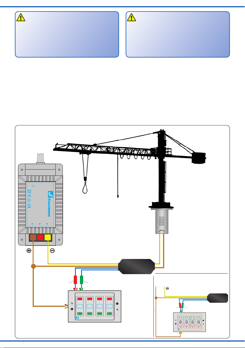
7. Technical Data
Connections: Operating voltage (brown, yellow),
Control (2x blue)
Systems: conventional analogue, DCC, MM
Operating voltage: 16 V
Operating current: < 100 mA
Standby current: < 30 mA
7. Technische Daten
Anschlüsse: Betriebsspannung (braun, gelb),
Steuerung(2xblau)
Systeme: konventionell analog, DCC, MM
Betriebsspannung: 16 V
Betriebsstrom: <100mA
Ruhestrom: <30mA
start the diorama mode by keeping the green
adress key / soft key pressed for about 2 – 3 sec-
onds.
Hint 2:
Modern digital command stations (e. g. Viess-
mann Commander, Märklin CS2, ESU EcoS 2)
provide the ability to set up the length of a switch-
ing pulse individually. If your command station
has this feature, we recommend setting the pulse
length to 200 – 250 ms.
Hint 3:
Some digital command stations (e. g. Märklin
CS2, ESU EcoS 2) don’t use different keys (red
and green) for turnouts and two aspect signals. In
this case, we recommend to use a three aspect
signal, so that you can use the keys „red“ and
„green“ individually.
6. Troubleshooting
Every Viessmann product is manufactured under
high quality standards and is tested before deliv-
ery. If there is a fault nevertheless, please check
at rst the wiring and especially the power supply.
If the product is damaged, send it in the original
package directly for repair to your local dealer or
to the Viessmann company (see below for ad-
dress).
This manual suits for next models
6
Table of contents